CAS 88306 - Intercom GEV - Free user manual and instructions
Find the device manual for free CAS 88306 GEV in PDF.

| Product Type | Intercom |
| Brand | GEV |
| Model | CAS 88306 |
| Dimensions (approx.) | 150 x 100 x 30 mm |
| Weight | 200 g |
| Power Supply | 2 x AA batteries or DC 9V adapter (not included) |
| Communication | Two-way audio |
| Door Release | Supports electric strike release |
| Monitor Function | Listen to outdoor unit without speaking |
| Call Buttons | One-touch call and door release |
| Volume Control | Adjustable ring and conversation volume |
| Installation | Wall-mounted indoor unit, surface or flush |
| Wiring | 2-wire connection to outdoor unit |
| Outdoor Unit Compatible | GEV CAS series outdoor station (not included) |
| Operating Temperature | 0°C to 40°C |
| Housing Material | ABS plastic |
| Color | White |
| LED Indicators | Power and call status |
| Ringer | Electronic chime, adjustable tone |
| Maintenance | Clean with soft dry cloth; avoid solvents |
| Safety | Low voltage, CE certified |
| Spare Parts | Battery cover, mounting screws available |
| Repairability | Replaceable battery compartment; consult manual |
| General Information | For residential use; user manual included |
Frequently Asked Questions - CAS 88306 GEV
User questions about CAS 88306 GEV
0 question about this device. Answer the ones you know or ask your own.
Ask a new question about this device
Download the instructions for your Intercom in PDF format for free! Find your manual CAS 88306 - GEV and take your electronic device back in hand. On this page are published all the documents necessary for the use of your device. CAS 88306 by GEV.
USER MANUAL CAS 88306 GEV
natural_image
Exterior view of a GEV mobile phone with attached wall-mounted door and cord (no signage or text in focus)
Typ: CAS
# 088306
Abb./Fig. 1
natural_image
Simple line drawing of a handheld device with a plug and cable (no text or symbols)1
3
4
text_image
Diagram of a mobile phone with labeled components including a sensor, coiled cable, and indicator lights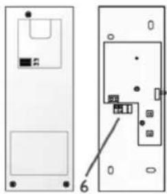
natural_image
Diagram showing two views of a device with labeled components, no readable text or symbols present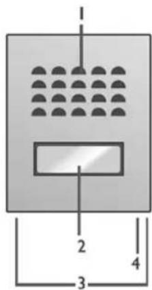
text_image
1 2 3 4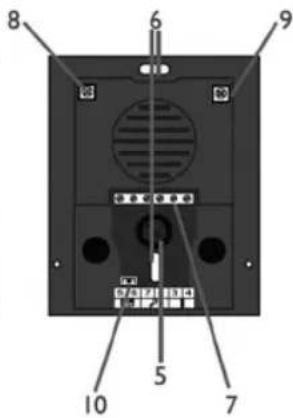
text_image
8 6 9 10 5 7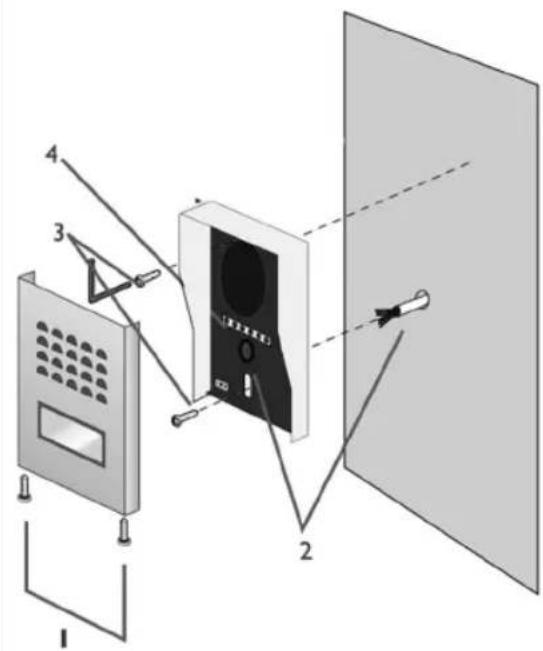
text_image
Diagram of a device assembly with numbered components, showing front panel, screen, and panel layoutnatural_image
Diagram of a door frame with internal components and a door, showing no text or symbolsb
natural_image
Simple line drawing of a mechanical device with two connectors and connecting wires (no text or symbols)Abb./Fig. 5
text_image
Diagram of a home control system with labeled components including telephone, door, and hand gesture indicator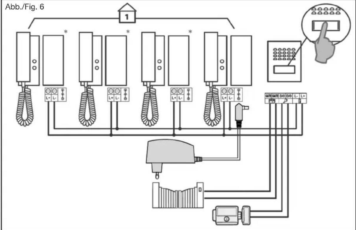
flowchart
graph TD
    A["1"] --> B["Wall-mounted device"]
    B --> C["L+ L-"]
    B --> D["L+ L-"]
    B --> E["L+ L-"]
    B --> F["L+ L-"]
    B --> G["L+ L-"]
    B --> H["L+ L-"]
    B --> I["L+ L-"]
    B --> J["L+ L-"]
    B --> K["L+ L-"]
    B --> L["L+ L-"]
    B --> M["L+ L-"]
    B --> N["L+ L-"]
    B --> O["L+ L-"]
    P["Hand gesture"] --> Q["Phone with 3D button icon"]
    R["Gate Gate"] --> S["DVD"]
    R --> T["DVD"]
    R --> U["L-"]
    R --> V["L+"]
In this Set (Fig. 1)
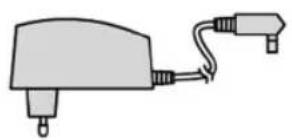
- Power Adapter
- Handset
- Outdoor Panel
- Rain Cover
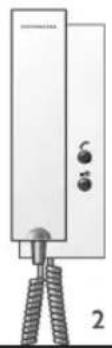
Components/ operating controls Handset (Fig. 2a)
- Loudspeaker
- Microphone
- Ring tone volume adjustment
- Intercom button
- Strike control (Door/Gate opener)
- Terminal block
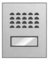
Outdoor panel (Fig. 2b)
- Loudspeaker
- Name plate/bell
- Screws
- Microphone
- Cable duct channel
- Holes for attaching the unit to the wall
- Terminal block
- Switch for setting the sound level for the speaker of the outdoor panel
- Switch for setting the sound level for the speaker of the handset
Introduction
This audio door phone system consist of a handset and an outdoor unit. With these you can establish an audio connection between the caller and yourself. Furthermore you have the option to add a door/gate strike (not included) into the system.
This audio door phone set uses a BUS-type protocol; i. e. just two wires are needed for all functions (ringing, speaking, listening, controlling the door/ gate strike)
Safety instructions
All warranty claims will be null and void in the event of any damage or loss caused by failure to observe these operating instructions. We accept no liability for any consequential losses or damage. We accept no liability for any personal injury or material damage caused by improper use or by failure to observe the safety advice. In these cases the guarantee and warranty are invalidated. For safety and authorization purposes it is not permitted to carry out any adaptation or conversion of the device.
- Do not disassemble the unit.
- Do not spray water on the indoor unit. Do not keep the outdoor unit where it will be exposed to extreme moisture.
- Do not drop or shock the unit.
- Remove the power cord from the wall socket when unit is not used for long periods.
- This apparatus is designed for moderate climates. Do not use in high humidity, dusty or dirty areas.
Installing
Attention: if you like to test the units before final installation then don't do this with both units inside The same room-this could lead to a Larsen-effect (an annoying acoustic feedback of the indoor panel).
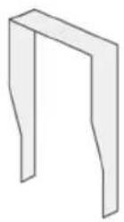
Installation of the outdoor panel (Fig. 3)
The outdoor panel is determined for wall-mounting.
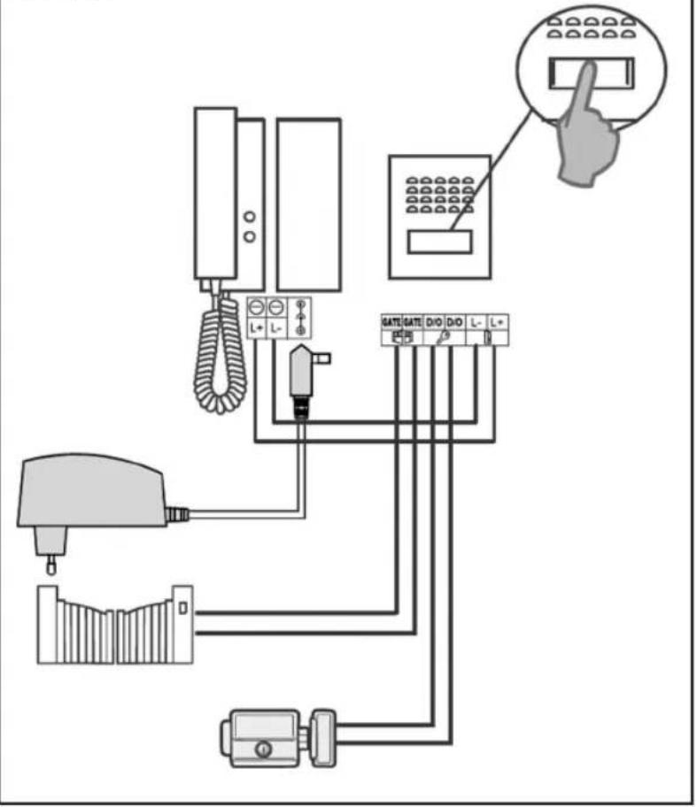
Remove the front panel of the outdoor unit by loosening the two screws on the bottom (Fig. 3/1). Run the cables coming from the indoor unit (handset) through the cable opening (Fig. 3/2). Likewise, if required, the cables coming from the electric door/gate opener, too. Screw the rain cover housing with two screws at the location you provided. (Fig. 3/3). Now you can connect the wires according to the wiring diagram (depending on the number of indoor units see Figure 5 or 6) to the appropriate terminals (Fig. 3/4).
Before closing the front plate again, you can do still volume settings on the fixed back plate (Fig. 2b/8 and 9). Use a small, suitable screwdriver and turn the screw without much force (Fig 2b/8 volume control of the outdoor unit. Fig 2b/9 volume control of the indoor unit).
Tip: Seal the joints between the outdoor unit and the wall from three sides with silicone. Let the joint on the bottom open to decrease the likelihood of condensation.
Mounting the indoor unit (Fig. 4a and 4b)
First, open the indoor unit for this purpose, go with a suitable screw driver on the right bottom in the recess and pry through slight leverage the top of the lower shell. Mount the lower shell with four screws at the designated place on the wall. Now connect the wires as shown in figure 5. or 6-depending on your desired level of expansion.
Installation of the handset/ installation of outdoor panel/ caption of the badge
Connecting the handset.
See figures 5 or 6-depending on your desired level of expansion. To avoid problems high- and low-voltage cables should never be in the same cable conduit. Connect the cables as shown in the figures described.
Connecting the handset to the outdoor panel: Connect the power supply with the inside socket. Connect "L+" and "L-" of the handset with the terminals "L+" and "L-" of the outdoor panel.
Connecting an electric door/or gate strike. You can optionally include an electric door and/or gate opener in this system. For the connection diagram see Figure 5 or 6.
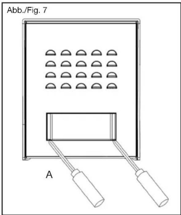
Caption of the name plate: Remove the cover of the bell in which you lever it by using a thin tool and carefully push it inside the notches (Fig. 7/A).
Set Up/Operation
Pressing on the push button of the outdoor panel, raises a signal on the handset (max. 6 times within 30 sec.). You can now pick up the phone and speak with the guest for a maximum of approx. 90 sec. To operate the electric door opener, briefly press (1 sec.) the —O button on the indoor unit. Important: It is essential that you use a door opener which has a memory function. Regarding the connection instructions see connection diagram 5 or 6. As a suitable electric door opener, we recommend such as item no. 007680 (110mm) or 007697 (250mm) from our GEV product range.
For connecting an electric gate opener connect the terminals "GATE" "GATE" of the outdoor panel and the two corresponding terminals (varies- depending on the manufacturer. Consult the manual of your gate drive engine) to your gate engine (terminals "GATE" "GATE" are dry contacts).
In case you have connected an external gate drive, enable this by a three-second push on the —O button on the phone.

Important: The functions can be executed only at the active unit and after lifting the handset.
text_image
Abb./Fig. 7 AAdditional information
You have the option to connect up to three additional interior handsets in parallel (fig. 6/ order no. 8830601). When connecting multiple handsets, it is sufficient if you are using a single power supply for all stations. However, this power supply has to be the one which is the closest to the outdoor panel. In order to
communicate internally, press the button. This will trigger a collective call and establish a connection to the remote handset which is being picked up first (for approx. 30 sec.). As long as there's an internal connection, the voice contact to the outdoor panel is locked. The intercom function is interrupted in case there is an external call coming in.

Rececling instructions
This device may not be disposed of with unsorted household waste.
Owners of old devices are required by law to dispose this device correctly. Contact your twon council for further information.
Specifications
| Handset (8830601) Specifications | |
| Dimensions 70[W] x 230[H] x 40 [D]mm | |
| Power Supply DC18V / 1,5A | |
| Power Consumption Max. 2W | |
| Connection System 2-wires | |
| Sounds 1 | |
| Max. Distance/ wire to be used Min. diameter of cable between last handset and outdoor panel up to 25m: ø 0,6mm-1,0mm up to 100m: ø 1,0mm-1.5mm | |
| IP 20 | |
| Mains adapter Specifications | |
| Power Supply 230 V~, DC 18V, 1,5A | |
| Outdoor panel (8830603) | Specifications |
| Dimensions 95[W] x120[H] x 30 [D]mm | |
| Current | DC12V (via indoor unit / handset) |
| Installation type | Outdoor- / Indoor unit : 2-wires |
| Door strike | Current 12V DC --- / max. 1.0A |
| Gate motor | Dry contact / closing time ca. 3 sec. |
| Type of installation | Wall mount |
| IP 44 | |
| Operating temperature | -10°C ~ 45°C |
| H | TR | CZ | SK | SLO | RO | PL | LT | LV | GR | RUS | FIN | DK | N | S | E | I | NL | F | GB | D |
GEV
Gutkes GmbH
Rehkamp 13
30853 Langenhagen
Germany
www.gev.de
service@gev.de
Hotline: +49 (0)180/59 58 555
CE
International calls may vary.