M1Y-YH5-185 - Saw Cotech - Free user manual and instructions
Find the device manual for free M1Y-YH5-185 Cotech in PDF.


| Product Type | Circular Saw |
| Brand | Cotech |
| Model | M1Y-YH5-185 |
| Voltage | 230 V AC, 50 Hz |
| Power | 1300 W |
| No-Load Speed | 4700 rpm |
| Cutting Depth at 90° | 63 mm |
| Cutting Depth at 45° | 42 mm |
| Blade Diameter | 185 mm |
| Blade Bore | 16 mm |
| Weight | 4.3 kg |
| Sound Pressure Level | 95.5 dB(A) K=3 dB(A) |
| Sound Power Level | 106.5 dB(A) K=3 dB(A) |
| Vibration Value | 2.462 m/s² K=1.5 m/s² |
| Adjustable Bevel Angle | 0° to 45° |
| Cutting Depth Adjustment | Yes, with locking lever |
| Parallel Guide | Yes, included |
| Blade Guard | Lower retracting guard with spring |
| Spindle Lock | Yes, for blade changes |
| Dust Port | Yes, for dust extraction |
| Included Accessories | Allen key, parallel guide |
| Safety Features | Lock button, blade guard, insulated handles |
| Maintenance | Keep vents clean; clean with soft cloth and mild soap |
| Disposal | Follow local regulations for electronic waste |
Frequently Asked Questions - M1Y-YH5-185 Cotech
User questions about M1Y-YH5-185 Cotech
0 question about this device. Answer the ones you know or ask your own.
Ask a new question about this device
Download the instructions for your Saw in PDF format for free! Find your manual M1Y-YH5-185 - Cotech and take your electronic device back in hand. On this page are published all the documents necessary for the use of your device. M1Y-YH5-185 by Cotech.
USER MANUAL M1Y-YH5-185 Cotech
Read the entire instruction manual carefully and make sure that you fully understand it before you use the equipment. Keep the manual for future reference.
Viktig information:
Original instructions
Bruksanvisning i original
Please read the entire instruction manual before use and save it for future reference. We reserve the right for any errors in text or images and for making any necessary technical changes to this document. If you should have any questions concerning technical problems please contact our Customer Services.
1. Safety
General Safety Instructions for Hand-Held Motor-Operated Electric Tools
Warning! Read all the instructions. Failure to adhere to the following instructions may lead to electric shocks, fires and/or serious injury. The term “electrical hand tools” in the warning text below refers to your mains operated or battery operated hand tool.
1) The work space
a) Keep the work space clean and well illuminated. Cluttered and poorly lit areas invite accidents.
b) Do not use electrical hand tools in explosive environments, i.e. nearby flammable liquids, gas or dust. Electrical hand tools generate sparks that could easily ignite dust or fumes.
c) Keep away from children and other spectators while using the electrical hand tool. Distractions can make you lose your concentration and control.
2) Electrical safety
a) The electrical hand tool's plug must fit correctly in the wall socket. Never modify the plug in any way. Never use an adaptor together with earthed electrical hand tools. Unmodified plugs and suitable wall sockets decrease the risk of electric shock.
b) Avoid body contact with earthed objects, such as pipes, radiators, ovens or refrigerators. There is an increased risk of electrical shock if your body is earthed.
c) Do not expose the electrical hand tool to rain or other wet conditions. If water gets inside an electrical hand tool it increases the risk of electrical shock.
d) Do not misuse the lead. Never use the lead to carry, drag or pull the plug out of the wall socket. Keep the lead away from heat, oil, sharp edges and movable parts. Damaged or tangled leads increase the risk of electrical shock.
e) When you use an electrical hand tool outdoors; use an extension cord suitable for this purpose. Use of an extension cord for outdoor use decreases the risk of electrical shock.
3) Personal safety
a) Pay attention to what you do and use common sense when using electrical hand tools. Never use an electrical hand tool if you are tired or under the influence of drugs, alcohol or medication. One moment of not paying attention while using an electrical hand tool may result in serious injury.
b) Use protective equipment. Always use safety glasses. Using protective equipment such as a face mask, slip resistant protective shoes, a helmet and ear defenders when needed decreases the risk of injury.
c) Avoid unexpected starts. Make sure that the switch is set to OFF before you connect the device to the wall socket. Never carry an electrical hand tool with one finger on the trigger or never connect the hand tool to a wall socket when the switch is set to ON, since it may result in injury.
d) Remove all service tools/keys before switching on the hand tool. A forgotten service tool on a rotating part of the electrical hand tool may result in injury.
e) Do not overreach. Make sure you stand steady and well balanced at all times. This gives better control in unexpected situations.
f) Wear suitable clothing. Do not wear loose fitting clothes or jewellery. Keep hair, clothes and gloves away from moving parts. Loose fitting clothes, jewellery or long hair could get caught in moving parts.
g) If the equipment for suctioning or collecting dust is available make sure it is connected and used properly. Using technical aids may reduce dust related hazards.
4) Use and maintenance of the electrical hand tool.
a) Do not overload the hand tool. Use a hand tool suitable for the work you are to perform. At the correct rate of feed, the correct tool will carry out the work better and more safely.
b) Never use the electrical hand tool if the switch does not work properly to turn on and shut off the tool. All electrical hand tools that cannot be operated by the switch are dangerous and must be repaired.
c) Unplug the lead from the wall socket before making any adjustments, changing accessories or storing the electrical hand tool away. These precautions reduce the risk of the electrical hand tool starting unexpectedly.
d) Store electrical hand tools that are not being used out of children's reach. Do not let people unfamiliar with the electrical hand tool or its instructions use it. Electrical hand tools can be dangerous if they get into the hands of inexperienced users.
e) Inspect electrical hand tools regularly. Check that all settings are correct, that no moving parts are getting jammed, that no parts are broken and for other reasons that might cause the electrical hand tool to malfunction. If something is damaged it must be repaired before use. Many accidents are caused by poorly maintained electrical hand tools.
f) Keep the tools sharp and clean. Properly maintained cutting tools with sharp blades are less likely to jam and are easier to control.
g) Use the electrical hand tool, accessories and such according to the instructions and in a way suitable for the type of electrical hand tool used. Using the electrical hand tool for work other than that for which it is intended could result in a dangerous situation.
5) Service
a) Repairs and service should only be performed by qualified persons, and only with original spare parts. This guarantees the safety of the electrical hand tool.
Safety Instructions Specific to Circular Saws
DANGER:
a) Keep hands at a safe distance from the saw blade. Keep your other hand on the front handle or on the housing. If you are holding the saw with both hands you cannot cut your hand.
b) Do not reach under the workpiece. The blade guard will not protect you from the blade underneath the workpiece.
c) Adjust the cutting depth to suit the thickness of the workpiece. Less than the length of one of the saw blade's teeth should be visible under the workpiece.
d) Do not hold the workpiece in your hands or across you leg.
Fasten the workpiece to a stable surface. It is important that the workpiece is correctly supported to minimise the risk of personal injury, to prevent the saw blade from binding and to prevent you from losing control of the saw.
e) Hold the electrical hand tool by its insulated handles whenever performing tasks where there is a risk of the saw cutting through hidden power cables or its own power cable. Contact with a live wire can lead to the metallic parts of the electrical hand tool becoming live and giving the user an electric shock.
f) When rip sawing: Use the parallel guide fence or guide rail. This will improve the precision of the sawing and reduce the chance of the saw blade binding.
g) Always use saw blades of the correct size and shape (diamond shaped or round). The saw blade must have the correct bore size (spindle hole diameter).
h) Never use damaged or incorrect washers or bolts to attach the saw blade. The washers and bolts for the saw blade are specially designed to achieve maximum performance and safety.
Additional Safety Instructions for all Saws
Reasons for kickback and preventing kickback:
- Kickback is a sudden reaction to a pinched, jammed or incorrectly aligned saw blade which causes the saw to jump back violently out of the workpiece towards the user.
- When the saw blade binds in the saw cut it stops rotating and the motor causes the saw to be thrown backwards towards the user.
- If the saw blade is twisted or distorted in the saw cut the teeth at the back of the saw blade can fasten in the workpiece and eject it towards the user.
Kickback is caused by the saw being used incorrectly, for the wrong purpose or under the wrong conditions and can be avoided by taking the following precautions:
a) Hold the saw firmly in both hands with your arms in a position to be able to parry a kickback. Stand to one side of the sawblade, not in line with it.
A kickback can cause the saw to jump backwards but it can be controlled if certain precautions are taken.
b) If the sawblade binds or if for some reason the work is interrupted. Release the trigger and hold the saw still until the sawblade has come to a complete stop. Never attempt to withdraw the saw from the workpiece when the blade is rotating, as this could cause a kickback. Examine and take the necessary measures to minimise the risk of blade jamming.
c) When starting the saw in a workpiece. Centre the sawblade in the saw cut and make sure that the teeth are not touching the material. If the saw blade has jammed it could wander upwards or be ejected from the workpiece when the saw is restarted.
d) Support large boards to reduce the risk of the saw blade binding or of the saw kicking back. Large boards tend to bow under their own weight. The boards need to be supported on both sides, near the saw cut and near the edge of the board.
e) Do not use blunt or damaged saw blades. Blunt or incorrectly set saw blades can produce saw cuts that are too narrow, producing too much friction and causing the saw blade to bind or the saw to kickback.
f) The cutting depth and angle adjusters must be locked in place before sawing begins. If any of the saw blade setting adjusters moves during cutting the blade could jam or the saw could kickback.
g) Be especially careful when plunge sawing in walls or objects where it is not possible to see what one is sawing. The saw blade could cut into objects that could cause kickbacks.
Safety Instructions for Saws Fitted with Inner Blade Guard
a) Make sure that the lower blade guard is properly closed before each use.
- Do not use the saw if the lower blade guard does not move freely and close immediately.
- Never clamp or bind the lower blade guard in the open position. If the saw is accidentally dropped the lower blade guard might be bent. Raise the lower guard using the handle and make sure that it can move freely and does not catch on the sawblade or anything else when sawing at all angles and depths.
b) Make sure that the spring on the lower blade guard works. If the guard and spring do not work properly they must be serviced before use. The guard might be slow due to damaged parts, sticky deposits or built-up waste.
c) The lower blade guard may only be removed manually in exceptional circumstances such as plunge sawing and compound sawing. Move the lower guard using the handle, and as soon as the sawblade makes contact with the material the guard must be released. For all other sawing the lower guard must work automatically.
d) Make sure that the lower blade guard is covering the blade before leaving the saw on a bench or on the floor. An unguarded rotating blade can cause the saw to move backwards and saw through everything in its path. Bear in mind that it takes time for the saw blade to come to a stop after the power switch has been released.
Guide to Safety Symbols

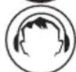

Read the entire instruction manual.
Always use ear protection.
Always use safety glasses.
2. Product Description
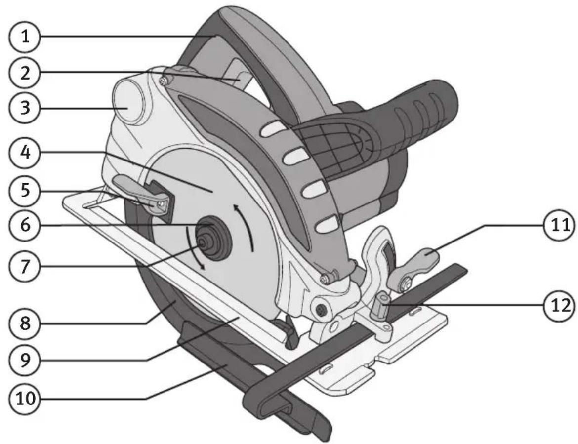
- Handle
- Power Switch
- Dust Port
- Saw Blade
- Lower Blade Guard Retracting Lever
- Flange Washer
- Socket Head Blade Screw
- Blade Guard (retracting)
- Shoe
- Parallel Guide
- Bevel Adjustment Locking Lever
- Parallel Guide Locking Knob
- Front Handle
- Lock Button for power switch
- Spindle Lock Button
- Depth Adjustment Locking Lever
Accessories (included)
- Allen Key

3. Controls and Functions
Power switch
Switching on and off
Start: Press in lock button (14) to enable the power switch (2) to be pressed.
Stop: Release buttons.


Spindle lock
Push in the spindle lock (15) to lock the spindle when changing the blade.
Guard retracting lever
Pull this lever (5) to open the saw blade guard.

natural_image
Close-up of a hand using a tool to adjust or install a mechanical component, with no visible text or symbols.4. Settings
Warning: Always unplug the saw before making any adjustments or repairs.
Setting the cutting depth

- Undo the locking lever (16).
- Lower the shoe (9) to the desired depth according to the marks.
- Tighten the locking lever.
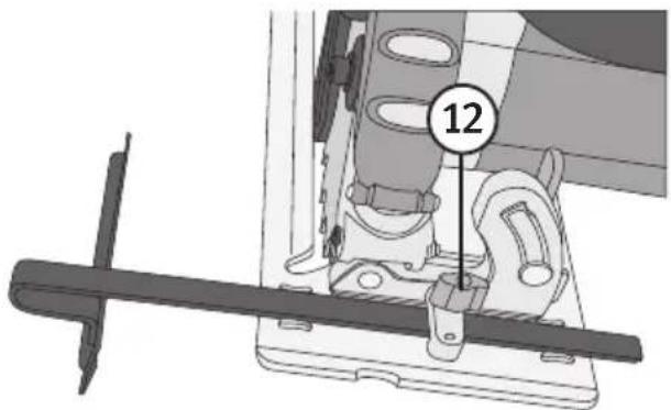
Setting the parallel guide
- Undo the locking knobs (12).
- Set the desired width.
- Tighten the locking screw.
- Check the measurement.
Setting the bevel angle

natural_image
Mechanical assembly diagram showing a bracket with mounting base and clamping mechanism (no text or symbols)- Undo the locking lever (11).
- Set the desired angle (0–45°) using the index mark.
- Tighten the locking lever.
- Check the angle using a try square if necessary.
Changing the blade
- Hold in the spindle lock (15) to prevent the blade (4) rotating.
- Undo the socket head screw (7) using the allen key (17).
N.B: The screw has a left-hand thread. - Move the blade guard (8) back and hold it using the retracting lever (5).
- Remove the flange washer (6) and then the saw blade.

- Attach the new blade in the reverse order. Make sure that it rotates in the right direction.
N.B: Make sure that the blade is correctly aligned and centred and that the fixing screw is tight before turning the saw on.
5. Troubleshooting
The following table contains information that might help diagnose and rectify common problems.
| Symptom Problem Solution | ||
| The motor does not start. | No power supply from the wall socket. | Check the connection. |
| Is the saw plugged in? Check the connection. | ||
| Weak power, slow sawing. | Blunt or damaged blade. Sharpen or replace it. | |
| The motor does not run at full speed under load. | Too much pressure applied. | Do not apply as much pressure to the blade. |
| The motor is overheated. Run the motor at full speed without any load for a while. | ||
| Heavy vibration. Loose blade. Tighten the screw and make sure that the blade is centred. | ||
6. Care
- Always keep the motor's ventilation openings free of dust and debris.
- Clean the circular saw whenever necessary using a soft cloth and washing-up liquid.
- Never use solvents or strong detergents.
7. Disposal
Follow local ordinances when disposing of this product. If you are unsure about how to dispose of this product contact your municipality.

8. Specifications
Voltage 230 V AC, 50Hz
Power 1300 W
No-load speed 4700 rpm
Cutting depth at 90° 63 mm
Cutting depth at 45^ 42 mm
Saw blade 185/16 mm
Weight 4.3 kg
Lpa (sound pressure) 95.5 dB(A) K: 3 dB(A)
Lwa (sound power) 106.5 dB(A) K: 3 dB(A)
Vibration Value ah 2.462 m/s ^2 K: 1.5 m/s ^2
Cirkelsåg
ART.NR 18-3087 MODELL M1Y-YH5-185-UK 30-9985 M1Y-YH5-185
natural_image
Close-up of a hand using a tool to adjust or install a mechanical component, with no visible text or symbols.4. Inställningar
natural_image
Mechanical assembly diagram showing a hand operating a bracket with a numbered label (11) pointing to a component, no readable text or symbols present.- Håndtak
- Strømbryter
- Tilkoblingspunkt for sponsuger
- Sagblad
- Manøverspak for sagdeksel
- Skive
- Inseksskrue for sagbladet
- Bevegelig beskyttelse
- Bunnplate
- Parallellanhold
- Låsespake for vinkelinnstilling
- Låseskrue for parallellanhold
- Fremre håndtak
- Låseknapp för strömbryter
- Spindellås
- Låsespak for innstilling av dybde
natural_image
Illustration of a hand using a tool to adjust or install a mechanical component, with no visible text or symbols.4. Innstillinger
- Løsne låsespaken (16).
- Senk bunnplaten (9) ned til ønsket sagdybde i henhold til markeringen.
- Dra til låseskruen.
natural_image
Mechanical assembly diagram showing a bracket with mounting base and clamping mechanism (no text or symbols)- Løsne låsespaken (11).
- Still inn ønsket vinkel (0–45°) mot indexmerket.
- Dra til låseskruen.
- Kontrollmål med en vinkelhake ved behov.
Bytte av sageklinge
natural_image
Close-up of a hand using a tool to adjust or install a mechanical component, with no visible text or symbols.4. Asetukset
natural_image
Mechanical assembly diagram showing a bracket with mounting base and clamping mechanism (no text or symbols)natural_image
Close-up of a hand using a tool to adjust or install a car wheel component, with no visible text or symbols.4. Einstellungen
natural_image
Mechanical assembly diagram showing a hand operating a bracket with a numbered label (11) pointing to a component, no readable text or symbols present.Declaration of Conformity
Declares that this product complies with the requirements of the following directives and standards
Machinery directive 2006/42/EC
EN 60745-1/A11:2010
EN 60745-2-5:2010
EMC directive 2004/108/EC
EN 55014-1/A1:2009
EN 55014-2/A2:2008
EN 61000-3-2/A2:2009
EN 61000-3-3:2008
Low voltage directive 2006/95/EC
EC type certificate, no. M8A 13 03 39641 491
Issued by the following notified body:
Klas Balkow
President
Insjön, Sweden, 2013-10-04
SVERIGE
KUNDTJÄNST Tel: 0247/4 45 00
Fax: 0247/4 45 09
E-post: kundservice@clasohlson.se
INTERNET www.clasohlson.se
BREV Clas Ohlson AB, 793 85 INSJÖN
NORGE
KUNDESENTER Tlf.: 23 21 40 00
Faks: 23 21 40 80
E-post: kundesenter@clasohlson.no
INTERNETT www.clasohlson.no
POST Clas Ohlson AS, Postboks 485 Sentrum, 0105 OSLO
SUOMI
ASIAKASPALVELU Puh.: 020 111 2222
Postal 10 – 13 Market Place
Kingston Upon Thames
Surrey
KT1 1JZ
DEUTSCHLAND

- Viktig information:
- Safety
- General Safety Instructions for Hand-Held Motor-Operated Electric Tools
- 1) The work space
- 2) Electrical safety
- 3) Personal safety
- 4) Use and maintenance of the electrical hand tool.
- 5) Service
- Safety Instructions Specific to Circular Saws
- DANGER:
- Additional Safety Instructions for all Saws
- Reasons for kickback and preventing kickback:
- Kickback is caused by the saw being used incorrectly, for the wrong purpose or under the wrong conditions and can be avoided by taking the following precautions:
- Safety Instructions for Saws Fitted with Inner Blade Guard
- Guide to Safety Symbols
- Product Description
- Accessories (included)
- Controls and Functions
- Power switch
- Spindle lock
- Guard retracting lever
- Settings
- Setting the cutting depth
- Setting the parallel guide
- Setting the bevel angle
- Changing the blade
- Troubleshooting
- Care
- Disposal
- Specifications
- Cirkelsåg
- Inställningar
- Innstillinger
- Bytte av sageklinge
- Asetukset
- Einstellungen
- Declaration of Conformity
- SVERIGE
- NORGE
- SUOMI
- DEUTSCHLAND
Brand : Cotech
Model : M1Y-YH5-185
Category : Saw