RocketRAID 1640 - NAS Highpoint - Free user manual and instructions
Find the device manual for free RocketRAID 1640 Highpoint in PDF.


| Type | RAID Controller Card |
| Brand | Highpoint |
| Model | RocketRAID 1640 |
| Interface | PCI Express x1 |
| Number of Ports | 4 x SATA (internal) |
| Supported Drives | SATA I / II / III |
| RAID Levels | 0, 1, 5, 10, JBOD |
| Maximum Capacity | Up to 4TB per drive (theoretical) |
| Form Factor | Low-profile bracket included |
| Dimensions | Approximately 167 x 64 mm |
| Weight | About 100 g |
| Power Consumption | Powered via PCIe slot (max ~10W) |
| Operating Temperature | 0°C to 50°C |
| Supported Operating Systems | Windows, Linux, macOS |
| Package Contents | Card, low-profile bracket, driver CD, SATA cables |
| Safety | Install in a well-ventilated slot, avoid static discharge |
| Cleaning | Use compressed air; do not use liquids |
| Repairability | No user-serviceable parts; replace entire card |
Frequently Asked Questions - RocketRAID 1640 Highpoint
User questions about RocketRAID 1640 Highpoint
0 question about this device. Answer the ones you know or ask your own.
Ask a new question about this device
Download the instructions for your NAS in PDF format for free! Find your manual RocketRAID 1640 - Highpoint and take your electronic device back in hand. On this page are published all the documents necessary for the use of your device. RocketRAID 1640 by Highpoint.
USER MANUAL RocketRAID 1640 Highpoint
Copyright © 2003 HighPoint Technologies, Inc.. This document contains materials protected by International Copyright Laws. All rights reserved. No part of this manual may be reproduced, transmitted or transcribed in any form and for any purpose without the express written permission of HighPoint.
Trademarks
Companies and products mentioned in this manual are for identification purpose only. Product names or brand names appearing in this manual may or may not be registered trademarks or copyrights of their respective owners.
Notice
Reasonable effort has been made to ensure that the information in this manual is accurate. HighPoint assumes no liability for technical inaccuracies, typographical, or other errors contained herein.
Backup your important data before using HighPoint's products and use at your own risks. In no event shall HighPoint be liable for any loss of profits, or for direct, indirect, special, incidental or consequential damages arising from any defect or error in HighPoint's products or manuals. Information in this manual is subject to change without notice and does not represent a commitment on the part of HighPoint.
Table of Contents
Chapter 1
Introduction
Serial ATA Overview 1-1
RAID Basics 1-1
RocketRAID 1640 1-2
Chapter 2
Adapter Installation
Adapter Layout 2-1
Adapter Installation 2-1
Verifying the Adapter's Installation 2-2
Driver Installation 2-3
Chapter 3
BIOS Configuration
Entering the BIOS Configuration Utility 3-1
Creating a Disk Array 3-2
Deleting Disk Arrays 3-5
Add/Remove Spare 3-6
Settings 3-7
View 3-8
Duplicate Critical RAID 1 array 3-9
Rebuild a Broken RAID array 3-10
Chapter 4
RAID Administrator
Introduction 4-1
Installation 4-1
Getting Started 4-2
Using the Software 4.4
Chapter 5 Trouble Shooting
Appendix A Glossary
Appendix B Contact Technical Support
Chapter 1 Introduction
This chapter discusses RAID-related Serial ATA background information, and the RocketRAID 1640 Serial ATA RAID solution.
Contents of this Chapter:
1.1 Serial ATA Overview
1.2 RAID Basics
1.3 RocketRAID 1640
HighPoint
1.1 Serial ATA Overview
Serial ATA is a high performance interface for IDE storage devices, and is the evolutionary replacement for the longstanding ATA physical storage interface. It is a practical add-on solution that is compatible with today's leading operating systems, and can be utilized alongside the existing PC architecture without the need for physical modification. Serial ATA is scalable and will allow for future enhancements of the computing platform. Serial ATA's efficient design further simplifies system integration.
1.2 RAID Basics
The term RAID is an acronym, and stands for Redundant Array of Independent Disks. RAID is a method of combining several hard disk drives (physical disks) into one logical unit (logical disk). This logical unit is referred to as the RAID array.
Arrays offer several advantages over standard, single-disk configurations - fault tolerance and/or higher data throughput (improved security and/or performance).
Hard disk drives can be combined into several different types of RAID arrays. These different combinations are referred to as RAID levels.
Different RAID levels offer different advantages, depending upon the number of hard disks used, and the security, cost, and performance requirements.
The most common types of RAID arrays include RAID 0, RAID 1, and RAID 5. RAID 5 is a popular choice: it is a very cost-effective solution, and provides both improved performance, and data security. It requires a minimum of three hard disk drives. RAID 5 includes a rotating parity array, thus, all read and write operations can be overlapped. RAID 5 arrays store parity information, but not redundant data.
There are also several types of combined-RAID levels, or hybrid arrays, such as RAID 1/0 (also known as RAID 10).
The table displayed on the following page describes some of the more common types of RAID arrays, the minimum number of hard drives required, and the benefits offered by each type RAID level.
| noitpircseD | #muminiM. srevir Dfo | ifcBe | |
| RAID 0 | Data Striping | 2 | Highest Performance without data protection |
| RAID 1 | Disk Mirroring | 2 | Data protection through 100% data duplication |
| RIO | dnagniorMgnipirtSataD | Higher performance with noietorpad | |
| RAID | gnipirtSataDgirRo 3Pyir | Highest performance noietorpadhitw | |
| JBOD | Disk Spanning | 2 | dnancietorpadperformance improving but full usage of disk yipa |
1.3 RocketRAID 1640
The RocketRAID 15xx, and 16xx series host adapters are Serial ATA RAID solutions developed by HighPoint Technologies, Inc.
The RocketRAID 1640 is a 4-channel Serial ATA 150 RAID 5 host adapter, that provides multi-level RAID support including RAID 0, 1, 1/0, 5, and JBOD. The RocketRAID 1640 is a high quality, cost effective, mass storage solution for home and business applications.
Below are the main features and benefits of the RocketRAID 1640:
- Supports data transfer rate up to 1.5 Gb/s
- IDE hard disk compatible (with RocketHead 100 converter)
- Better connectivity (low pin count, small cable and connector)
- Thin cable for easy routing and improving cooling inside a computer chassis
- Supports RAID 0, 1, 10, 5 and JBOD
- Bootable disk or disk array support
- Supports OSs like: Windows 9x/ME/NT4.0/2k/XP, Linux (Red Hat, SuSE, Turbo, Caldera), and FreeBSD
- Windows-based RAID configuration & management software tool (compatible with BIOS)
- Real-time monitoring of device status and error alarm with popup message box
- Event log for easy troubleshooting
Serial ATA RAID Function and High Performance
Serial ATA provides multi level RAID supports including RAID 0, 1, 1/0, 5 and JBOD, as well as powerful software management functions. RocketRAID 1640 Serial ATA RAID controller's performance increase to 1.5Gb/s.
Thin, unrestrictive Cable Design is easy to Configure, and improves Chassis Cooling
Serial ATA's efficient design further simplifies system integration. Serial ATA cables are considerably more compact than standard IDE cables, and are much easier to configure and arrange within a computer's chassis.
The thin serial ATA cables also significantly improve airflow within the computer's chassis - this helps combat the risk of damage to vital PC components due to excessive heat retention.
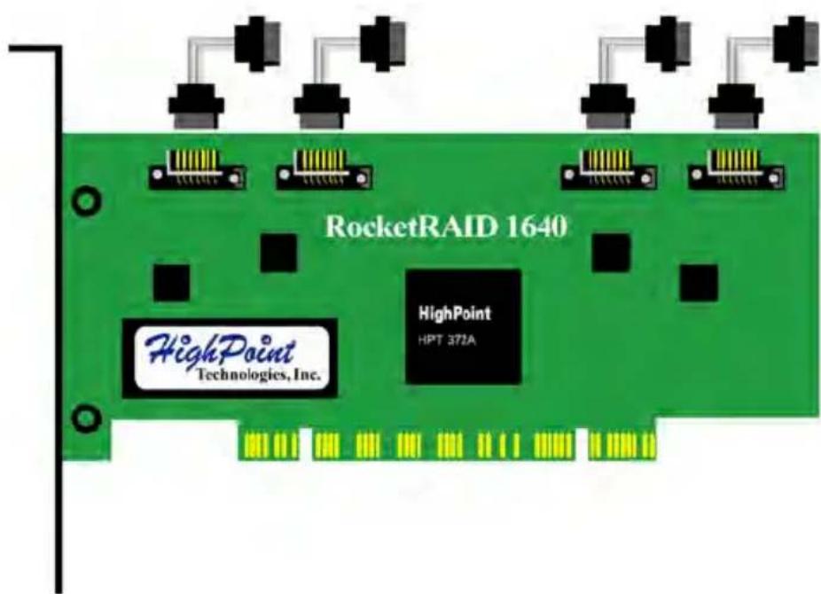
IDE Hard Disk Compatible
The RocketRAID 1640 is compatible with the RocketHead 100 IDE to Serial ATA converters.
This device allows users to connect ATA100 and ATA133 parallel IDE hard disk drives to the Serial ATA controller. This converter is ideal for those who do not have Serial ATA hard disks, or want to avoid using multiple host adapters.
Chapter 2
Adapter Installation
This chapter will describe how to install the RocketRAID 1640 adapter into a computer, and how to properly attach hard drives to the adapter. Please make sure to read through this chapter carefully before installing the adapter.
Contents of this Chapter:
2.1 Adapter Layout
2.2 Adapter Installation
2.3 Verifying the Adapter's Installation
2.4 Driver Installation
If you have questions about the installation process, please contact our technical support department.
HighPoint
2.1 Adapter Layout
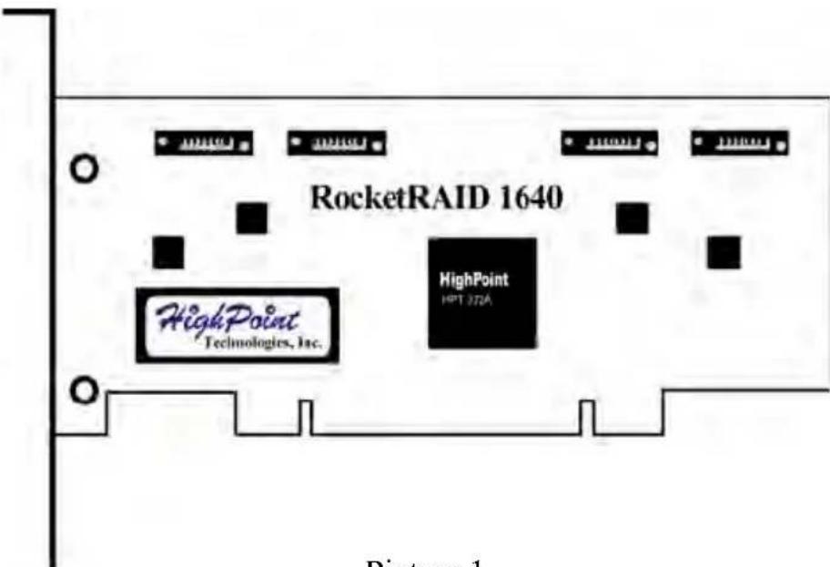
Picture 1
2.2 Adapter Installation
natural_image
Diagram of a laboratory setup with a test tube, beaker, and needle inserted (no text or labels)Picture 2
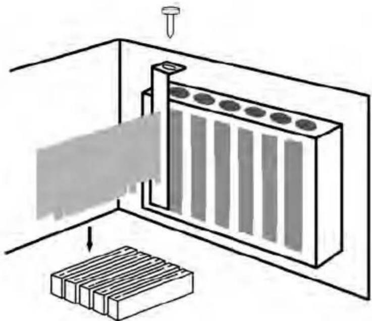
Follow these steps to install and connect hard disks to the host adapter.
- Shut down the computer and unplugs the power supply.
- Please discharge static electricity from your body by touching a conductor.
- Remove the corresponding card bracket from the back of the computer chassis.
-
Insert the RocketRAID 1640 adapter steadily into a PCI slot on motherboard and then settle with a screw (see picture 2).
-
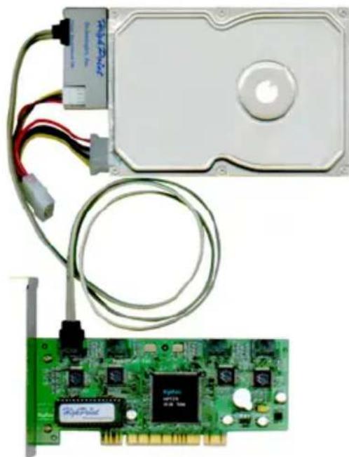
Connect Serial ATA hard disk to RAID adapter with Serial ATA cable; If IDE hard disks are used, set jumper of the IDE hard disks to master position and connect the cable and IDE hard disks by using RocketHead100 (see picture 3).
-
Connect all power supply connectors to hard disks.
-
Replace the cover of computer chassis.
natural_image
Electronic components including a hard disk, connected cable, and a green circuit board (no visible text or symbols)Picture 3
Note:
- If the adapter or hard disk is not recognized, please refer to the Trouble Shooting chapter.
2.3 Verifying the Adapter's Installation
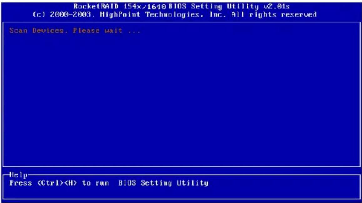
After installing the RocketRAID 1640 host adapter, and connecting the hard disks as required, the computer can be turned on. Please pay close attention to the information displayed on the screen while starting the computer. If the following information is displayed (see the following page), the RocketRAID 1640 host adapter has been successfully installed and recognized by the computer.
Next, the RocketRAID 1640 adapter's BIOS will scan the connected hard disks. Please pay attention to the screen display (See the following picture). If all of the connected hard disks are displayed on the screen, the disks have been properly installed and recognized by the computer.
![RocketRAID 151x/1640 BIOS Setting Utility v2.01s Channel Device Name Array Name Capacity(GB) Mode 1:Master MAXTOR 6L0Z0J1 20.54 ATA/133 1:Slave No Device 2:Master ST315320A 15.30 ATA/66 2:Slave No Device 3:Master MAXTOR 6L0Z0J1 20.54 ATA/133 3:Slave No Device 4:Master Maxtor 4G160J8 163.92 ATA/133 4:Slave No Device Help ↑↓→←: Next Item [Enter1:Select [ESC]:Quit](/content/2026/05/1026680/images/d626892df2c7469867e619e78f1ceeaa1f502eb3cb954459734097655d7e380a.jpg)
2.4 Driver Installation
After the RocketRAID 1640 host adapter is installed and recognized by the computer, allow the operating system to boot. The host adapter's device driver must be installed.
● Windows 9x/ME
Installation
After the operating system has booted, Windows will automatically detect the newly installed adapter, and prompt the user to install its driver. Follow these steps to install the driver.
- After the Add New Hardware Wizard window appears, press the Next button until the following window appears:
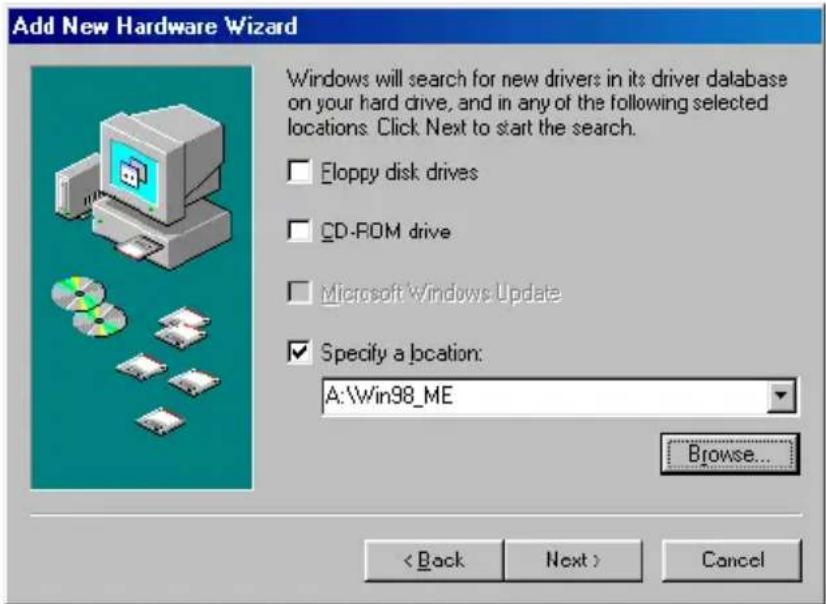
- Insert the driver diskette, then select the Specify a location item and type in the driver location: A:\Win9x_ME, then click on the Next button to continue. (If installing the driver from a CD, make sure to input the correct path. For example: D:\RR15xx\Windows\Driver\Win9x_ME)
- Confirm the following dialogue windows. Windows will then display a prompt to restart the system. Select NO - do not restart the computer at this time.
Windows will then find a second device. Repeat steps 1 and 2, then click YES to restart the computer.
Verify Installation
After installing the driver, and after Windows reboots:
- Right-click on My Computer icon on desktop, and then select Properties item from the menu.
- From the popup window, activate Device Manager item, see the following page:
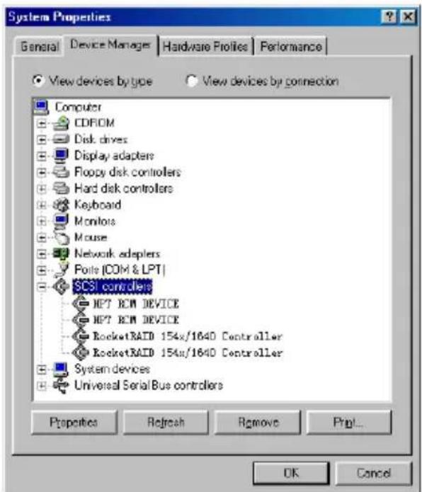
Double click the SCSI controllers entry. Four items should be displayed - two entries for the RocketRAID 154x/1640 Controller, and two entries for the HPT RCM DEVICE. If any of these items is not displayed, or any "?" or "!" marks are displayed near the device icons, the driver had not been correctly installed. Delete these items, and reinstall the driver.
If all four items are properly displayed, the driver has been installed correctly.
Note:
- If the system is not restarted after installing the driver, "!" marks may displayed near the device entries.
- Windows NT4.0
Installing the RocketRAID 1640 driver for an existing Windows NT 4.0 system
-
Click Start ---> Settings ---> Control Panel, then double-click on the SCSI Adapters icon.
-
A new window should be displayed - click on the Driver tab, then click on the Add button.
-
In the following window, click on the Have Disk...button. The following window will appear (see the picture below).
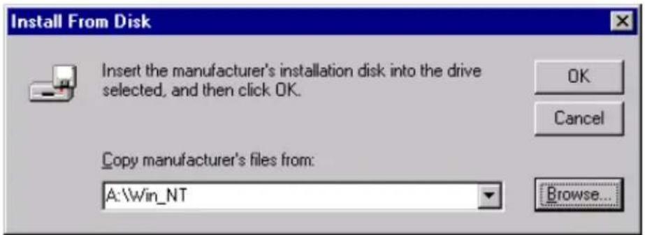
- Insert the driver diskette, and type in the path of driver location: A:\Win_NT in the above window, then click OK. (If installing the driver from a CD, make sure to input the correct path. For example: D:\RR15xx\Windows\Driver\Win_NT)
- Within the following window, select RocketRAID 154x/1640 Controller item, and then click OK.
- Confirm the following system prompts to finish the driver installation. When installation is complete, restart the computer.
Installing the RocketRAID 1640 driver during Windows NT 4.0 installation
- Press F6 key when the installation program prompts Setup is inspecting your computer's hardware configuration.
- NT setup will then proceed normally. Later, NT setup will display a new window with an option to press the "S" key to specify other devices. Please press the "S" key.
- In the following window, select Other, then press the ENTER key to confirm.
- Setup will then prompt you to insert the driver diskette. Insert the driver diskette, and press ENTER to continue.
- Next, select RocketRAID 154x/1640 Controller for WinNT4.0, and press ENTER to continue.
- The following window will list the devices that will be installed. The RocketRAID 154x/1640 Controller should be included.
(If other devices need to be installed, please install them at this time. If all of the devices have been installed, please proceed to the next step.) - Press ENTER to confirm the devices to be installed and continue the installation of Windows NT4.0.
Verify Installation
After the driver has been installed and the computer is restarted:
-
Click Start ---> Settings ---> Control Panel, and then double-click on SCSI Adapters icon.
-
Within the SCSI Adapters window, see next page:
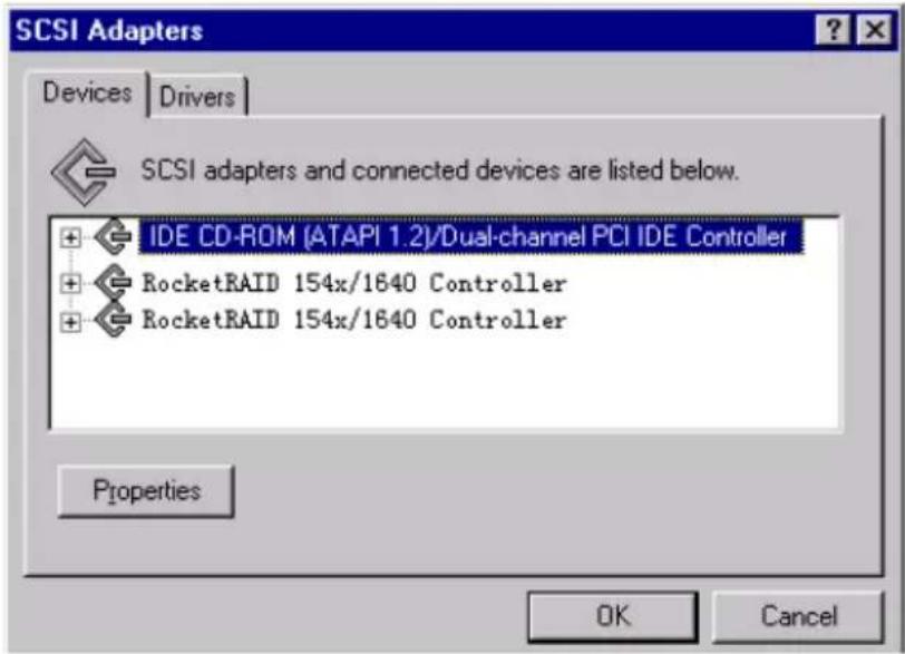
Make sure the RocketRAID 154x/1640 Controller entries are displayed. This indicates that the driver has been successfully installed. If these entries are not displayed, or any "?" or "!" marks are displayed near the device entries, the driver had not been correctly installed. Delete these items, and reinstall the driver.
● Windows 2000
Installing the RocketRAID 1640 driver for an existing Windows 2000 system
After the operating system has booted, Windows 2000 will automatically detect the newly installed adapter, and prompt the user to install it's driver. Follow these steps to install the driver.
- When the Found New Hardware Wizard window appears, click Next button to continue, in the following window, please select Display a list ... and then click Next to continue.
- In the following window, select SCSI and RAID Controllers and then click Next to continue.
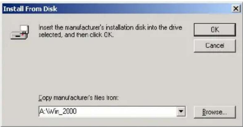
- In the following window, click Have Disk..., then Insert the driver diskette and type in the driver location: A:\Win_2000, then click OK to continue. (If installing the driver from a CD, make sure to input the correct path. For example: D:\RR15xxWindows\Driver\Win_2000)
- In the following window, select RocketRAID 154x/1640 Controller, then click Next to continue.
- Confirm the follow up windows and click the Finish button to continue.
- Next, Windows will find the HighPoint RCM device. Please confirm the Digital Signature Not Found window when it appears, and restart the computer when prompted.
Installing the RocketRAID 1640 driver during Windows 2000 installation
- Booting from the CD-ROM - when the Windows 2000 Setup blue screen appears, look towards the bottom of the screen. Windows will prompt you to press the F6 key if you want to install a third part SCSI or RAID driver. Please press the F6 key at this time.
- The setup procedure will continue, and will later instruct you to press the "S" key to specify additional adapters. Please press the "S" key at this time.
- Then the setup program will prompt user to insert the driver diskette. Please insert the driver diskette, then press ENTER to continue.
- The following window will display several driver options. Please select the RocketRAID 154x/1640 Controller for Windows 2000 option, and press ENTER to continue.
- The following window will list the devices that will be installed. The RocketRAID 154x/1640 Controller should be included.
(If other devices need to be installed, please install them at this time. If all of the devices have been installed, please proceed to the next step.)
- Press ENTER to continue Windows 2000 setup.
Verify Installation
After the driver has been installed, and the computer has been restarted:
- Right-click My Computer icon, then select Properties item from the popup menu.
- In the popup window, select the Hardware item, then click on the Device Manager button.
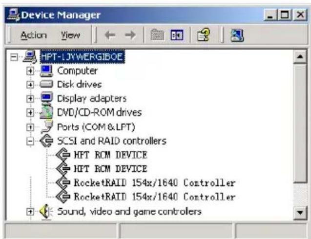
Make sure four items should be displayed (see the image last page) - two entries for the RocketRAID 154x/1640 Controller, and two entries for the HPT RCM DEVICE. If any of these items is not displayed, or any "?" or "!" marks are displayed near the device icons, the driver had not been correctly installed. Delete these items, and reinstall the driver.
If all four items are properly displayed, the driver has been installed correctly.
- Windows XP
Installing the RocketRAID 1640 driver for an existing Windows XP system
After the operating system has booted, Windows XP will automatically detect the newly installed adapter, and prompt the user to install it's driver. Follow these steps to install the driver.
- When the Found New Hardware Wizard window appears, select Install from a list or specify location(Advanced), and click Next to continue.
- In the following window, please select Don't search, I will choose the driver to install, then click Next to continue.
-
In the following window of device list, please select SCSI and RAID controllers, and then click Next to continue.
-
In the next window, click on Have Disk..., then type in the driver location: A:\Win_XP into the following window, then click OK to continue.(If installing the driver from a CD, make sure to input the correct path. For example: D:\Driver\Win_XP)
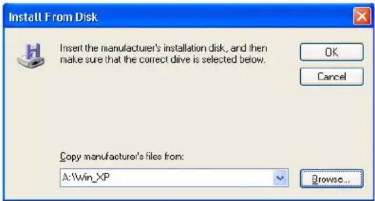
-
In the following window, select RocketRAID 154x/1640 Controller, then click Next to continue.
-
In the following window, click on Continue Anyway, then click Finish in the following window.
-
Next, Windows will find the HighPoint RCM device. Please confirm the Digital Signature Not Found window when it appears. Windows will then display a prompt to restart the system. Select NO - do not restart the computer at this time. Windows will then find a second device. Repeat steps 5 and 6, then click YES to restart the computer.
Installing the RocketRAID 1640 driver during Windows XP installation
- Booting from the CD-ROM - when the Windows XP Setup blue screen appears, look towards the bottom of the screen. Windows will prompt you to press the F6 key if you want to install a third part SCSI or RAID driver. Please press the F6 key at this time.
- The setup procedure will continue, and will later instruct you to press the "S" key to specify additional adapters. Please press the "S" key at this time.
- Then the setup program will prompt user to insert the driver diskette. Please insert the driver diskette, then press ENTER to continue.
- The following window will display several driver options. Please select the RocketRAID 154x/1640 Controller for Windows XP option, and press ENTER to continue.
- The following window will list the devices that will be installed. The RocketRAID 154x/1640 Controller should be included.
(If other devices need to be installed, please install them at this time. If all of the devices have been installed, please proceed to the next step.)
- Press ENTER to continue Windows XP setup.
Verify Installation
After the driver has been installed, and the computer has been restarted:
- Right-click My Computer icon, then select Properties item from the popup menu.
- In the popup window, select Hardware tab and then click Device Manager button.
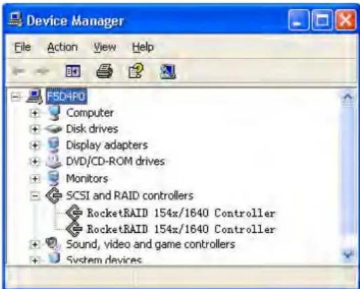
Make sure the RocketRAID 154x/1640 Controller entries are displayed (see the image displayed above). This indicates that the driver has been successfully installed. If these entries are not displayed, or any "?" or "!" marks are displayed near the device entries, the driver had not been correctly installed. Delete these items, and reinstall the driver.
Chapter 3
BIOS Configuration Utility
The RocketRAID 1640 includes a built-in BIOS configuration utility. This utility provides options to configure and manage hard disks or disk arrays connected to the RocketRAID 1640 host adapter. The BIOS configuration utility is especially useful when arrays must be created before and OS is installed.
Contents of this Chapter:
3.1 Entering the BIOS Configuration Utility
3.2 Creating a Disk Array
3.3 Deleting Disk Arrays
3.4 Add/Remove Spare
3.5 Settings
3.6 View
3.7 Duplicate Critical RAID 1 array
3.8 Rebuilding a Broken RAID array
3.1 Entering the BIOS Configuration Utility
When the following information is displayed on the screen during bootup, press CTRL+H key access the BIOS configuration utility.
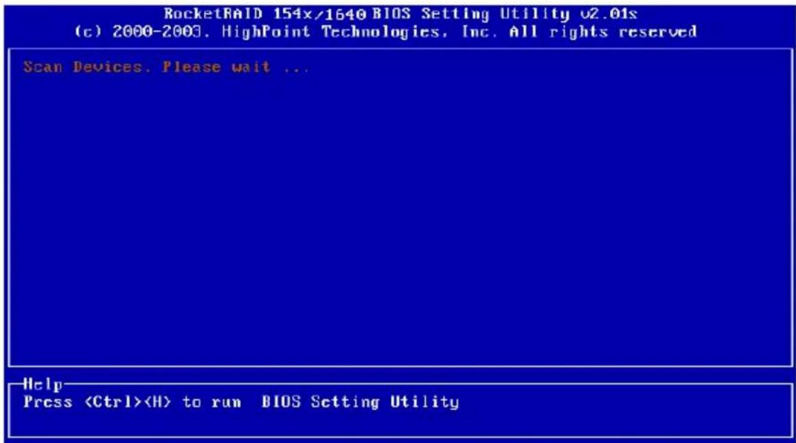
The main interface of BIOS configuration utility is as below:
![RocketRAID 154x/1640 BIOS Setting Utility v2.01s Channel Device Name Array Name Capacity(GB) Mode 1:Master MAXTOR 6L0Z0J1 20.54 ATA/133 1:Slave No Device 2:Master ST3153ZOA 15.30 ATA/66 2:Slave No Device 3:Master MAXTOR 6L0Z0J1 20.54 ATA/133 3:Slave No Device 4:Master Maxtor 4G160J8 163.92 ATA/133 4:Slave No Device Help ↑↓>>: Next Item [Enter]:Select [ESC]:Quit](/content/2026/05/1026680/images/50f94a5cec28f58a159b5ad3cd8bee2d13d2648e6be91fc93ab8ad3a8c958bb6.jpg)
Main Menu: This column lists all currently available operation commands.
Status: This column lists all the hard disks and disk arrays connected to the adapter. When this column is activated, select the target device to perform a specific operation.
Help: This column displays help information about the current selected item and the prompt on available operations.
3.2 Creating a Disk Array
Follow these steps to create a disk array:
- Within the Menu column of the main interface, use the arrow keys to highlight the Create command and press ENTER. This will open a list of array modes (also referred to as RAID levels). See the image below:
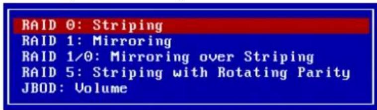
Use the arrow keys to highlight the array mode you wish to create, and press ENTER to confirm the selection.
- Within the Menu column of the main interface, use the arrow key to highlight Array Name, and press ENTER. A dialogue box will appear (see the image below)
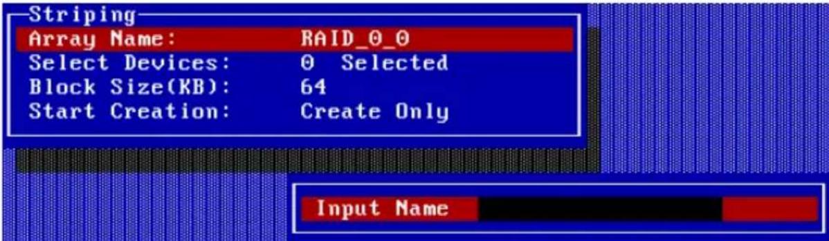
Name the array using the keyboard, and press ENTER to continue.
- Within the Menu column of the Main interface, use the arrow key to highlight the Select Devices option, and press ENTER. This will activate the Status column (see the image below):
| Channel Device Name Array Name Capacity(GB) Mode | |||
| (1) 1:Master WDC WD84AA | 8.45 ATA/66 | ||
| (2) 2:Slave ST310823A | 10.02 ATA/100 | ||
| 3:Master Maxtor 31024H1 | 10.24 ATA/100 | ||
| 4:Master ST315320A | 15.30 PIO 0 | ||
Highlight the disks that you wish to use, and press ENTER to select them. After all of the disks have been selected, press the ESC key to return to the creation step menu.
- When creating a RAID 0, 1/0, or 5 array, a block size must be selected. Within the Menu column of the main interface, use the arrow keys to highlight the Block Size option, and press ENTER. Select a block size from the pop-up list (see the following page):
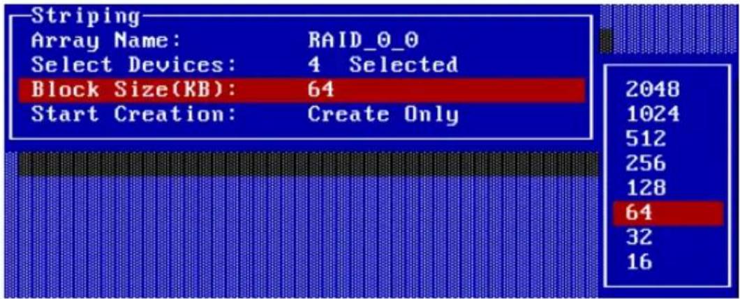
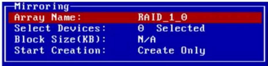
If user selected a RAID 1array, JBOD array in step 1, the Block Size is N/A, see below:
- Within the Menu column of the main interface, use the arrow keys to highlight the Start Creation option, and press ENTER.
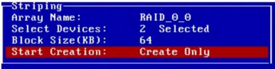
When creating RAID 0, 1/0 or JBOD array, simply use the arrow key to highlight the Start Creation process and press ENTER. A warning message will then be displayed. See the image below:
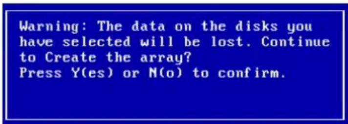
Please pay close attention to this warning. Press N to cancel, and press Y to continue.
When creating a RAID 1 (mirror) array, several options will be displayed: Create only, or Create and Duplicate. The Create and Duplicate option will preserve the data on the source disk 1) and will copy it to the mirror or target disk (disk 2).
Create only should only be used when stating from scratch - this option will not preserve the data on either disk. See the following page:
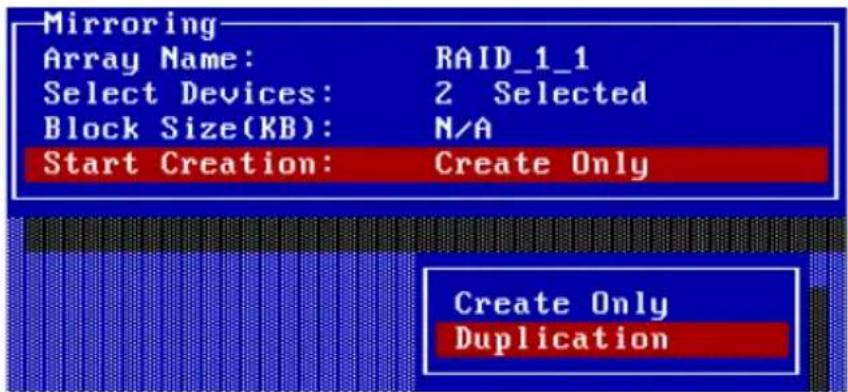
A warning message will then be displayed. See the image below:
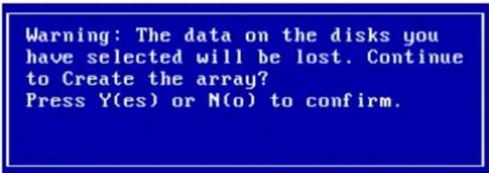
Please pay close attention to this warning. Press N to cancel, and press Y to proceed with he duplication process.
When creating a RAID 5 array, several options will be displayed: Zero Build and No Build. Zero Build will initialize the disk. Zero Build or No Build will start over if interrupted, but No Build will create an array without initialization. See the image below:
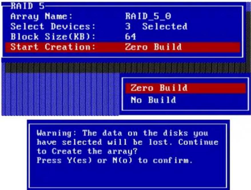
If the No Build option is selected, warning messages will be displayed. See the following page:
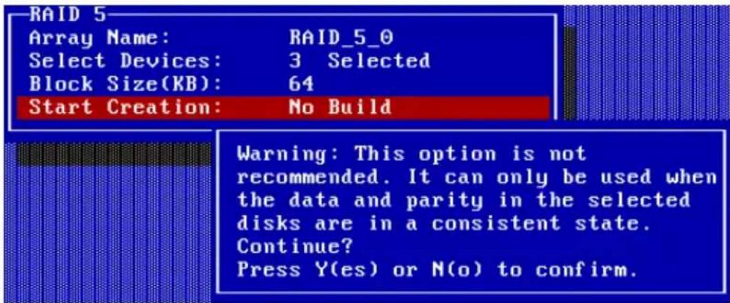
Please pay close attention to this warning. Press N to cancel, and press Y to continue. If Y is selected, another warning message will be displayed. See the image below:

Select Y to create the array, and N to cancel.
Warning:
Please pay close attention when warning message are displayed during step 5. When creating RAID 0, 5 and JBOD arrays, selecting Y will destroy all data on the selected disks.
3.3 Deleting Disk Arrays
Follow these steps to delete a disk array:
- Within the Menu column of the main interface, use the arrow key to highlight the Delete option, and press ENTER. The Status column will be activated. See the following page:
![RocketRAID 154x/1640 BIOS Setting Utility v2.01s Array Name RAID Level Capacity(GB) Block Size(KB) RAID_0_0 Striping 30.60 64 Help Delete a RAID array attached to HPT374. ↑↓→: Next Item [Enter]:Select [ESC]:Backward](/content/2026/05/1026680/images/5ed8c7b62574372b7f3e7c6d8d8db9376c31ec866adeb2fc0f5527cc5a65317c.jpg)
Highlight the target disk array, and press ENTER to delete it.
- A warning message will then appear. See the image below
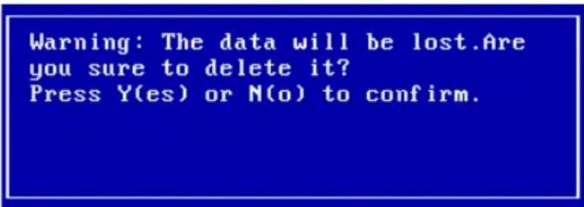
Pay close attention to this warning. Press Y to delete the selected array, or press N to cancel.
3.4 Add/Remove Spare
Follow these steps to add spare or delete spare from spare pool:
- Within the Menu column of the main interface, use the arrow key to highlight the Add/Remove Spare option, and press ENTER. The Status column will be activated. See the image below:
| Channel | Device Name | Array Name | Capacity(GB) Mode |
| 1:Master | MAXTOR 6L020J1 | 20.54 ATA/133 | |
| 2:Master | ST315320A | 15.30 ATA/66 | |
| 3:Master | MAXTOR 6L020J1 | 20.54 ATA/133 | |
| 4:Master | Maxtor 4G160J8 | 163.92 ATA/133 |
Use the arrow keys to highlight the target disk, and press ENTER to add it to the spare pool. To remove a disk from the spare pool, highlight it and press ENTER.
- After a disk has been added to the spare pool, it's status will be marked as Spare. See the image below:
| Channel | Device Name | Array Name | Capacity(GB) Mode |
| 1:Master | MAXTOR 6L020J1 | 20.54 ATA/133 Spare | |
| 1:Slave | No Device | ||
| 2:Master | ST3153Z0A | 15.30 ATA/66 | |
| 2:Slave | No Device | ||
| 3:Master | MAXTOR 6L020J1 | 20.54 ATA/133 | |
| 3:Slave | No Device | ||
| 4:Master | Maxtor 4G160JB | 163.92 ATA/133 | |
| 4:Slave | No Device |
3.Repeat step 1 to add to or remove any additional disks from the spare pool.
Warning:
Adding a disk to the spare pool will delete all data on that disk.
See the image below:
| Channel D1:Master MAXT2:Master ST313:Master MAXT4:Master Maxt | Warning: The content on the single disk will be lost if the single disk is changed into a spare disk. Are you sure to do this?Press Y(es) or N(o) to confirm. | (GB) Mode54 ATA/13330 ATA/6654 ATA/13392 ATA/133 |
Select Y to continue and N to cancel.
3.5 Settings
Follow these steps to set a disk or disk array:
- Within the Menu column of the main interface, use the arrow key to highlight the Select Settings option, and press ENTER. The following list will be displayed:
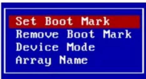
- Use the arrow keys to select Set Boot Mark, and highlight the target disk or disk array and press ENTER. This option will instruct this disk or array to act as the boot unit, when motherboard has designated the RocketRAID 1640 to act as the boot device.
| Logical Device | Type | Capacity(GB) | Status |
| MAXTOR 6L020J1 | 20.54 | BOOT | |
| ST315320n | 15.30 | HDD1 | |
| MAXTOR 6L020J1 | 20.54 | HDD2 | |
| Maxtor 1G160J8 | 163.92 | HDD3 |
-
Highlight the Remove Boot Mark to remove the boot designation from a selected boot disk or disk array. Use the arrow keys to highlight the target disk or disk array and press ENTER.
-
To change a disk or disk array's mode setting, use the arrow keys to highlight the Device Mode option and press ENTER. This will display a series of possible mode settings. See the image below:
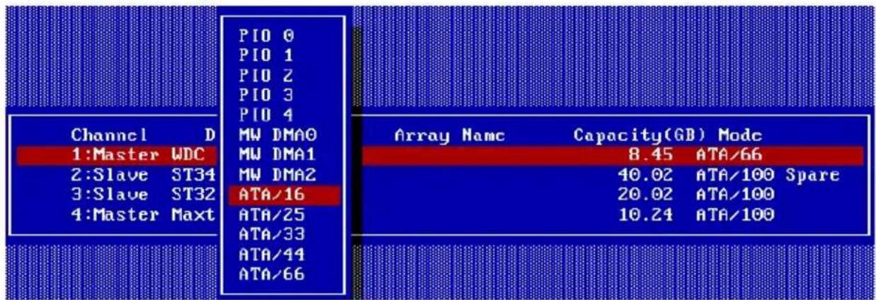
- To rename a disk array, use the arrow keys to highlight the Array Name option, and press ENTER. This will open a dialogue box (see the image below).

Use the keyboard to create an array name, then press ENTER.
3.6 View
Follow these steps to view a disk or disk array:
- Within the Menu column of the main interface, use the arrow key to highlight the View option, and press ENTER. The following list will be displayed:
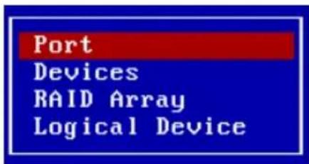
- To view the Port information, use the arrow keys to highlight the Port option and press ENTER. A new window will be displayed (see the image below):
| Channel | Base Port | Control Port | DMA Port | Interrupt |
| 1 | 0xCBOO | 0xCCO2 | 0xD800 | 0x000A |
| 2 | 0xD000 | 0xD402 | 0xD808 | 0x000A |
| 3 | 0xDC00 | 0xE002 | 0xEC00 | 0x000A |
| 4 | 0xE100 | 0xEB02 | 0xEC08 | 0x000A |
- To view Device information, use the arrow keys to highlight the Device option and press ENTER. The following window will be displayed (see the following page):
| Channel | Device Name | Array Name | Capacity(GB) Mode |
| 1:Master | MAXTOR 6L020J1 | RAID_0_0 | 20.54 ATA/133 |
| 1:Slave | No Device | ||
| 2:Master | ST315320A | RAID_0_0 | 15.30 ATA/66 |
| 2:Slave | No Device | ||
| 3:Master | MAXTOR 6L020J1 | 20.54 ATA/133 | |
| 3:Slave | No Device | ||
| 4:Master | Maxtor 4G160J8 | 163.92 ATA/133 | |
| 4:Slave | No Device |
- To view information about a particular disk/RAID Array, use the arrow keys to highlight the RAID array option, and press ENTER. The following window will be displayed (see the image below):
| Array NameRAID_0_0 | RAID LevelStriping | Capacity(GB)30.60 | Block Size(KB)64 |
- To view information about logical drives, use the arrow keys to highlight the Logical Drives option, and press ENTER. The following window will be displayed (see the image below):
| Logical Device | Type | Capacity(GB) | Status |
| RAID_0_0 | Striping | 30.60 | HDD5 |
| MAXTOR 6L020J1 | 20.54 | HDD6 | |
| Maxtor 4G160J8 | 163.92 | HDD7 |
3.7 Duplicate Critical RAID 1 array
If a RAID 1 duplication procedure has been canceled, or any problem or fault that may have lead to an inconsistency between the data on the source disk/disk array, and the backup data on the target disk/disk array, is detected, the BIOS will display a warning message during the computer's boot-up procedure. The faulty disk/disk array will be marked as critical in the status column, and the BIOS will automatically prompt you to duplicate the array to repair the inconsistency. See the image below:
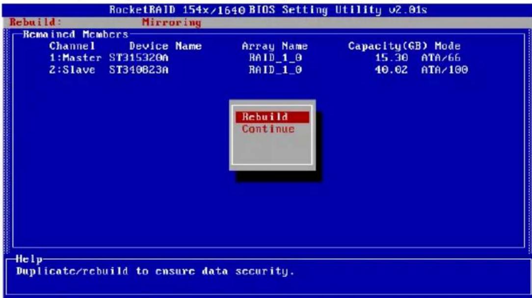
Select the Rebuild option to duplicate, or select Continue to boot to skip this procedure. The array can be repaired using after the operating system has booted, using the RAID software (chapter 4 covers this subject).
3.8 Rebuilding a Broken RAID array
If the BIOS detects that a RAID 1 has been broken, when a spare disk is unavailable, several options will be displayed. See the image below:
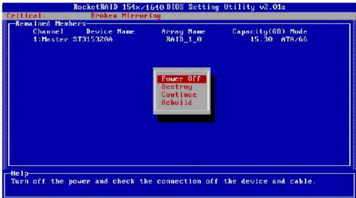
1. Power off
This command provides the option to power off the system and replace the failed disk with a fresh unit. If the system does not support APM (advanced power management), you must power down the computer manually. After replacing the failed disk, and starting the system, access the BIOS configuration utility, and rebuild the damaged array (see option 4 - Rebuild).
2. Destroy
This option is designed for use with RAID 1 arrays, and will delete the RAID relationship. The data on the surviving disk will be left intact.
3. Continue
This option will hide the broken array and continue to boot to the operating system.
4. Rebuild
This option will rebuild a damaged array using a fresh disk, and duplicate the data from the surviving member of the original array to this fresh disk.
a) If this option is selected, the following window will be displayed:
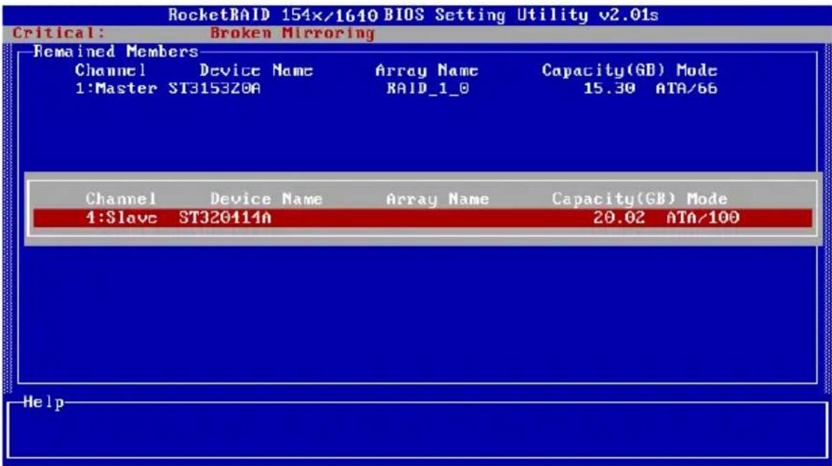
Highlight the target disk and press ENTER to select it.
b) The BIOS will then start the rebuild/duplication process. See the image below:
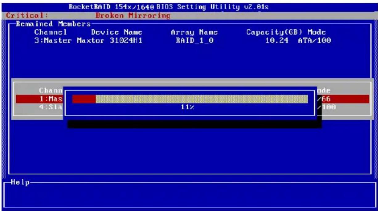
The ESC can be used to cancel the procedure anytime during the rebuild/duplication process.
c) Continue to boot - this option will allow the BIOS to skip the rebuild option, and boot into the operating system.
Chapter 4 ATA RAID Software
This chapter discusses the HighPoint Storage Management Software.
Contents of this chapter:
4.1 Introduction
4.2 Installation
4.3 Getting Started
4.4 Using the Software
HighPoint
4.1 Introduction
The HighPoint Storage Management Software is comprised of two separate utilities: HighPoint Storage Management Console and HighPoint Storage Management Service
To simplify this guide, we will refer to the HighPoint Storage Management Console as the Management Console, and the HighPoint Storage Management Service as the Management Service.
Additionally, the system that hosts the Management Console may be referred to as the administrative system, and the system that hosts the Management Service may be referred to as the remote system.
The Management Console can be installed to any computer, and is used to monitor and control RAID configurations utilized by other computers (remote systems). From the Management Console, you can monitor one or more of these remote systems. The software can be used to create, monitor, delete, or modify various types of RAID arrays, including RAID 0, RAID 1, RAID 10 (1/0), RAID 5, and JBOD.
The Management Service is designed to run continually on computers that utilize one or more HighPoint ATA RAID controller. It is designed to receive and carry out commands issued by the Management Console: logging events, executing scheduled tasks, and creating or rebuilding RAID arrays.
4.2 Installation
Follow these steps to install the Serial ATA RAID software:
- Insert the HighPoint ATA RAID Management Software setup floppy diskette 1 into your floppy drive, and double click the setup.exe icon to start the installation procedure. When prompted, insert the remaining disks, and follow the instructions displayed by the setup program.
- Confirm the follow-up dialogue windows to finish the installation.
- When installation is complete, restart the computer. (Note: It is strongly recommended that you exit all windows programs before running this Setup program.)
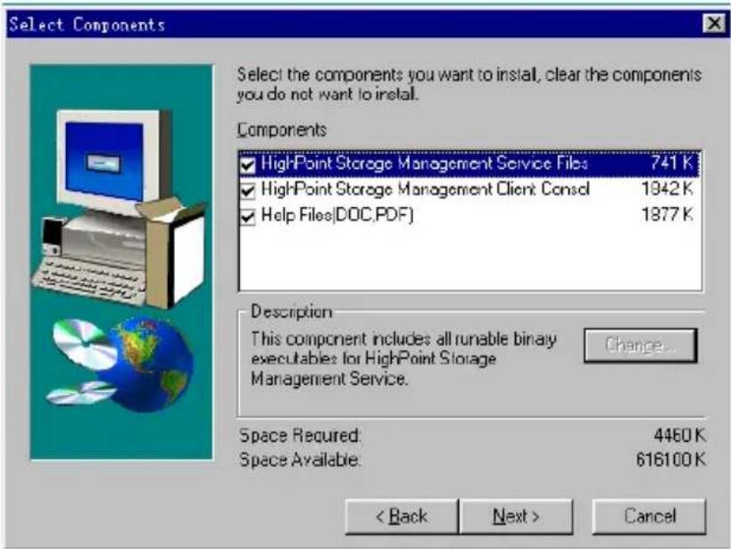
- You can install both the Management Console, and the Management Service, to a single computer, or install the Management Console to one computer, and the Management Service to another computer (or several others). You can access the Management Service through the Management Console software. See the following page:
4.3 Getting Started
With the Default option selected, the setup program will create a Program group. Click on the Start button, then click the Programs selection and highlight the HighPoint entry. The following items should be displayed:
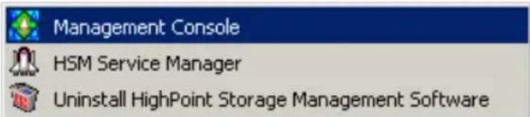
HSM Service Manage For the administrative system
Management Consolve For the remote systems (or, any system
using a HighPoint RAID controller)
Uninstall... Uninstall the program
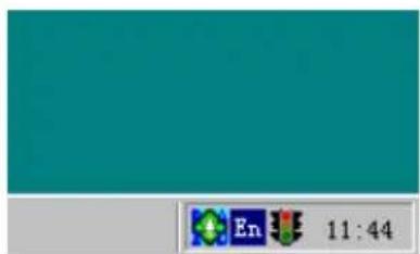
Small icons ( ) will be displayed towards the bottom right-hand corner of the system's desktop (near the clock feature), to indicate that the software is running. See the image below:
1. Starting the Management Service
Double click the small ( ) icon to open the main interface of the Management Service:
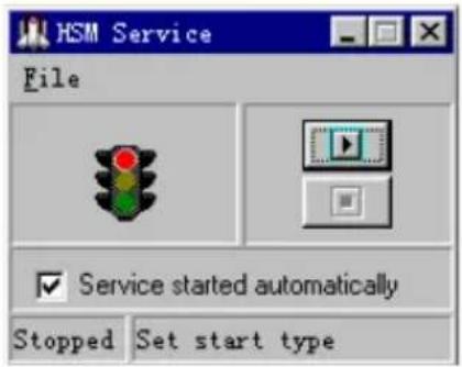
The colored traffic lights represent the Service's status. The (▶) button can be used to activate or disable the Server Side software. A green "light" indicates the Software is active. A red "light" indicates the software is disabled.
2. Starting the Management Console
Double click the small ( ) icon to open the main interface of the Management Console software. The main interface has five tabs: File, Configuration, Management, View, and Help. Click on different tabs to activate different commands. See the image below:
File: This tab includes four sub-tabs: Remote Control, Server configuration, User Management, Password and Exit. Click the Exit button to exit Serial ATA RAID software.
Mangement: This tab includes six sub-tabs: Array Management, Device Management, Spare Management, Event Notification, Task Schedule and Refresh. These sub-tabs will be introduced later.
View: This tab includes two sub-tabs: Event View, and Icon View. The system will display the connection status of all the attached disks or disk arrays. The Event View window will display all of the events recorded while the software is running. The Icon View window explains the functions of the various icons used by the software.
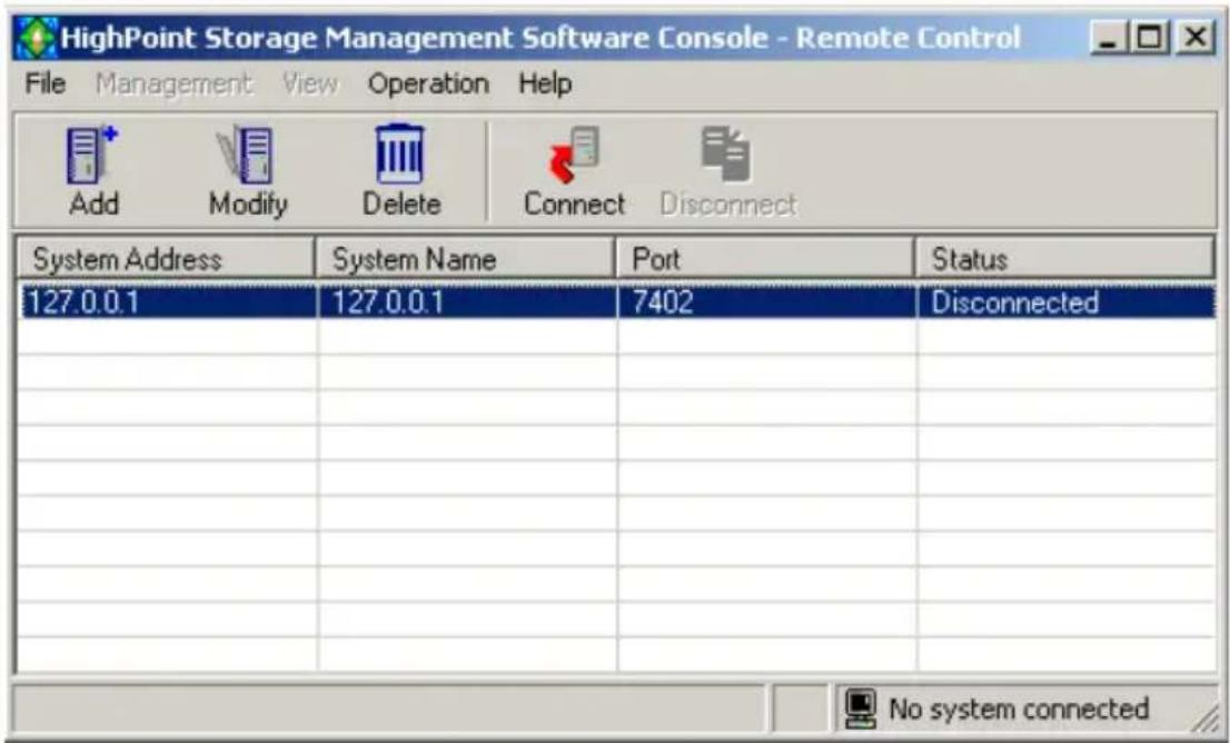
Operation: This tab includes 5 sub-tabs: Add, Modify, Delete, Connect, and Disconnect.
Help: Click on this tab to view the Help topics, or check information about this version of the HighPoint Storage Management software. The help feature summarizes the functions of this software, and includes a topic search option.
4.4 Using the Software
The File tab
This software allows you to connect to remote computers that utilize HighPoint RAID controllers, via an Internet connection. After verifying the system's name and password, the software can be used to monitor, repair or modify existing RAID arrays utilized by the remote system. The software can also be used to modify user information, and the Management Service's configuration.
1. Remote Control
Click on the File tab, and select the Remote Control item from the menu. This will open the Remote Control Window.
- Adding a Connection
The Add button is used to add a new system to the Remote Control window. Systems added to the Remote Control window automatically appear each time the program is launched.
Click on the Add button from the Remote Control window, or select Add from the Operation tab to add a new system. See the image below:
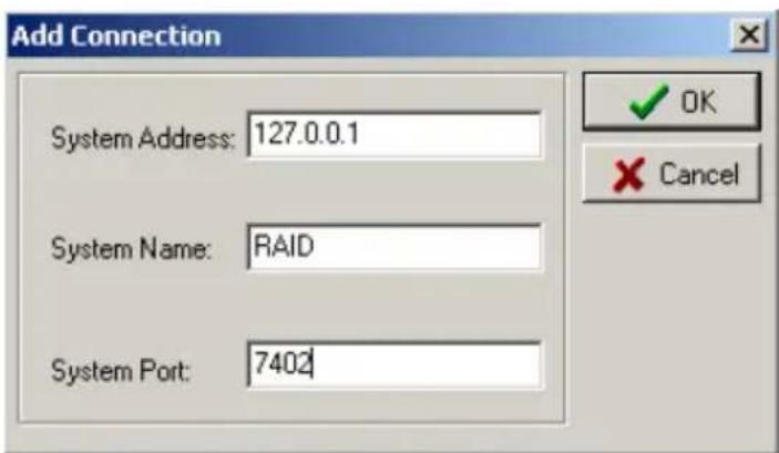
Enter the remote system's address, name and port information into the appropriate fields, then click OK. Make sure the Address and Port information is correct - the software will be unable to connect to the remote system if any information is left out.
Note: If you do not need to connect to a remote system, and only need to work with arrays attached to the system you are working with, choose to add a new system, and enter the following information into the appropriate fields:
System Address: 127.0.0.1
System Name: RAID (make sure that capital letters are used) - use "hpt" as the pass word
System Port: 7402
● Modifying a Connection
This option is used to modify a connection (the name and Port). First, select one of the connections from the connections list, and then click the Modify button on the toolbar, or click on the Operation tab and select the Modify option. This will open a new window. See the image below:
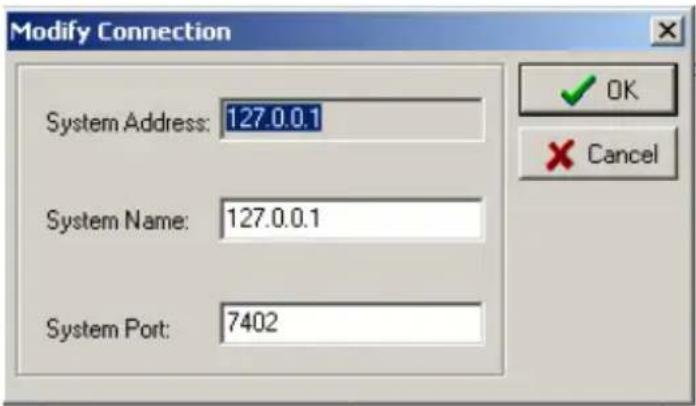
After modifying the system name and system port information, click OK.
Note: The System Address information cannot be altered. In order to modify this item, the connection must be deleted and recreated.
- Deleting a Connection
This option will delete a connection from the connection list. Select one of the connections from the connection list, and click the Delete button on the toolbar, or Click on the Operation tab and select the Delete option. Click OK to delete the selected connection from the connection list. A warning message will be displayed. See the following page:
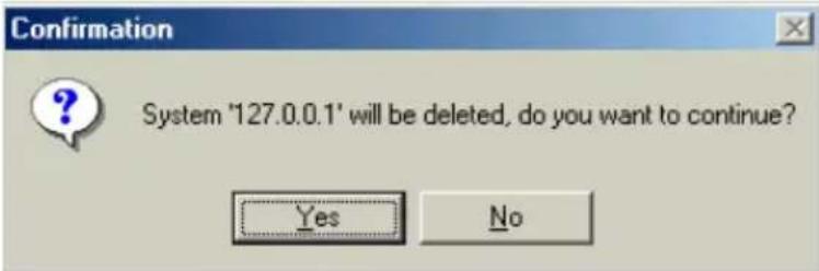
Click on Y to delete the connection, or N to cancel this operation.
Note: Make sure the connection is not active - it must be disconnected before it can be deleted from the connection list.
- Connect to a Remote System
Click the Connect button on the tool bar, or click on the Operation tab and select the Connect item from the menu. You can also double-click the desired connection from the connection list to start this procedure. A new window will be displayed. See the image below:
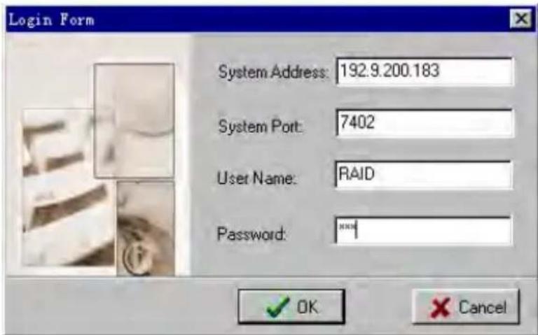
Click OK to connect to the selected system, and Cancel to cancel this operation.
Note: You can only connect to one remote system at a time. Be sure to close the previous connection before attempting to connect to another system.
● Disconnecting a Remote System
To disconnect from a remote system, click on the Disconnect button on the toolbar, or click on the Operation tab, and select the Disconnect option. A new window will be displayed. See the image below:
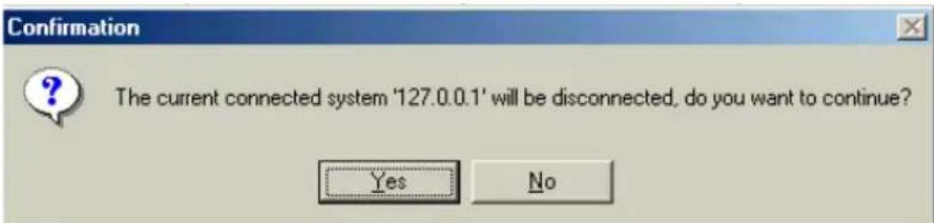
Click OK to disconnect from the remote system, or Cancel to cancel this operation.
2. Remote Server Configuration
Click on the File tab, and select the System Configuration option from the menu. A new window will be displayed. See the image below:
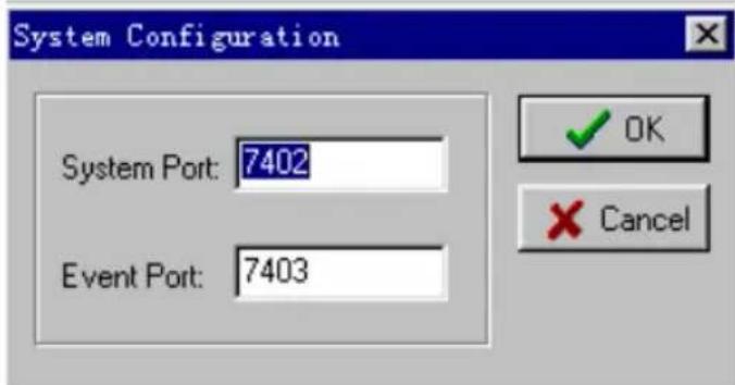
You can modify the values of the System Port and Event Port fields.
- System Port
When connecting to the remote system, make sure the port value is correct. The default value is 7402 - this may have to be changed.
Event Port
The Management Console software retrieves event information through this port. The default value is 7403 - make sure this value is not the same value used for the System Port.
After setting the system configuration, you should close and restart the RAID software - this will ensure that the changes made will take effect.
3. User Management
Click on the File tab, and select User Management from the menu. This will open a new window. See the image below:
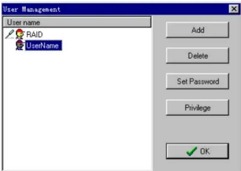
The User Management displays information about all valid user accounts, and provides options to create, delete or modify user information.
- Adding a user
Follow these steps to add a new user:
1) Click on the Add button, and enter a user name and password. Confirm this password, then click on the Next button. See the image below:
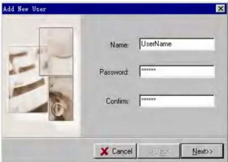
2) Click on the Privilege button, and select the appropriate security privileges. Click on the Finish button. See the image below:
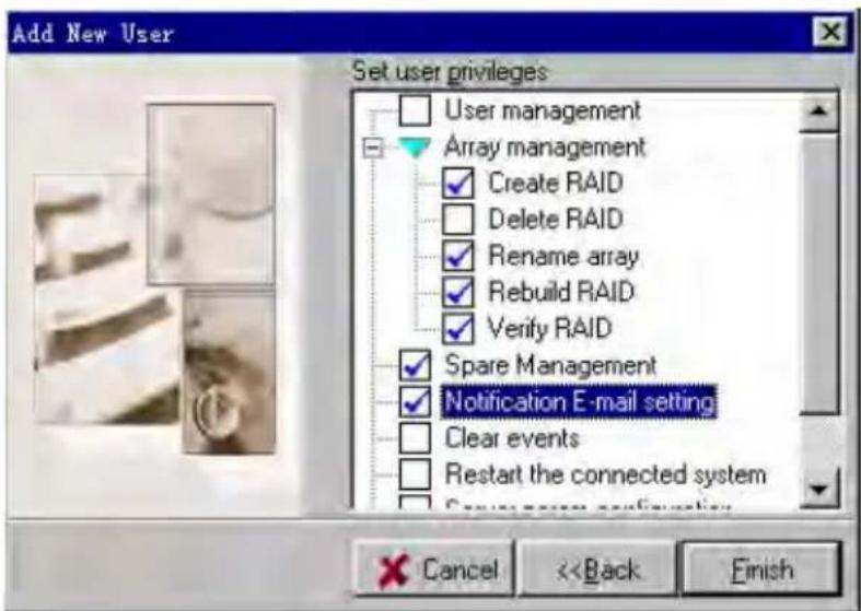
3) Once the new user has been successfully added, the user's entry will appear in the User Management window.
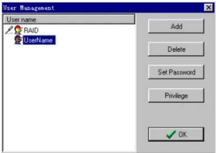
- Deleting a User
Highlight and select a user entry from the User Management window, and click on the Delete button. The selected user will then be deleted.
Make sure the selected user is not connected to the remote computer - the Delete option will be disabled if the user is connected to the system.
- Set a User Password
Highlight and select a user entry from the User Management window, and click on the Set Password button. You can also click on the File tab, then select the Password option.
●Changing a User's Password
Highlight and select a user entry from the User Management window, and click on the Set Password button. You can also click on the File tab, then select the Password option. Enter the new password and click the OK button to confirm. Click on the Cancel to cancel the operation.
● Changing a User's Privilege level
Highlight and select a user entry from the User Management window, and click on the Privilege button. The following window will be displayed:
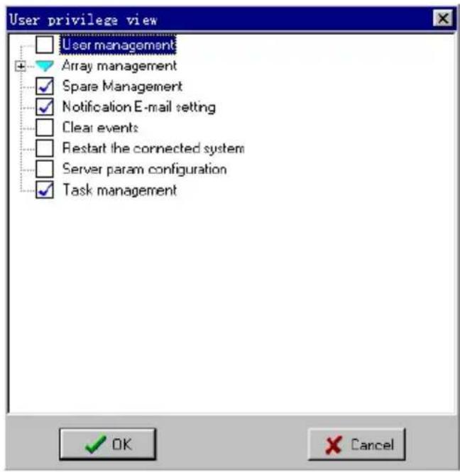
Make the appropriate changes and click the OK button to confirm. Click on the Cancel button to cancel this operation.
● The Management tab
The HighPoint Storage management Console software provides a variety of RAID management features. These features are listed under the RAID Management menu displayed under the main interface window. Sub-menus display additional information about RAID configurations, and make management an simple task.
1. Array Management
Click on the Management tab, and select the Array Management option. This will open a new window, which will display all of the logical drives attached to the RAID controller. The logical drives are grouped according to physical disk. See the image below:
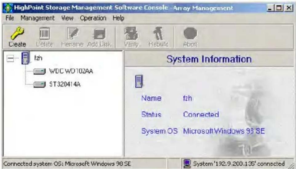
Clicking on a drive icon to display information about this disk - the right side of the screen will provide information about the physical disk, including the model, location, transfer mode and capacity. Clicking on an array icon will provide information about the selected array, including the name of the array, the RAID type or level, and capacity.
- Creating an Array
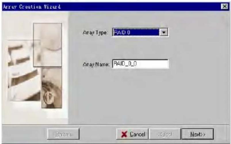
If the Create Array option has been enabled under the Privilege settings, and enough disks are available to create an array, click the Create button located on the toolbar. You can also click on the Operation tab, and select the Create option. This will open the Array Creation Wizard window.
Step 1:
Select the type of Array
Select the type of array you wish to create using the drop-down menu. If JBOD was selected, you can jump directly to Step 4.
If any other type of array is selected, enter an array name, and click the Next button. If you do not wish to name the array, leave the Array Name field blank, and click the Next button.
If RAID 0, 10, or 5 was selected, proceed to step 3.
Step 2:
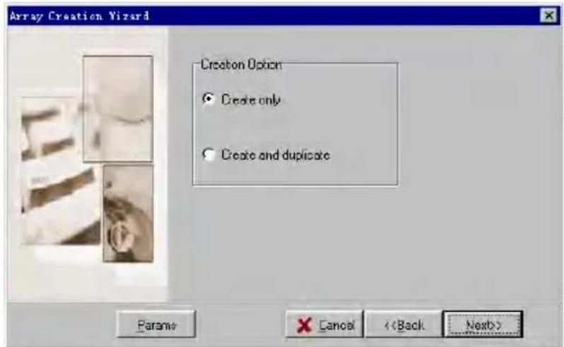
RAID 1 Creation Option:
If RAID 1 was selected, select from the following array options (see the image below):
1) Create Only
This option will create a RAID 1 array between the selected disks, but will not preserve any of the data. The data on both disks will be lost.
2) Create and Duplicate
This option will create a RAID 1 array between the selected disks, and will copy the data from the Source disk, to the Mirror (also referred to as the target) disk. All data that was originally stored on the Mirror disk will be deleted.
Step 3:
Specify the Block Size
When creating a RAID 0 or 10 array, select the Block Size from the drop-down menu, and click on the Next button. See the image below:
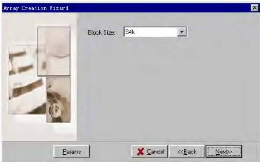
When creating a RAID 5 array, select the Block Size from the drop-down menu, and the appropriate Creation Option. See the following page:
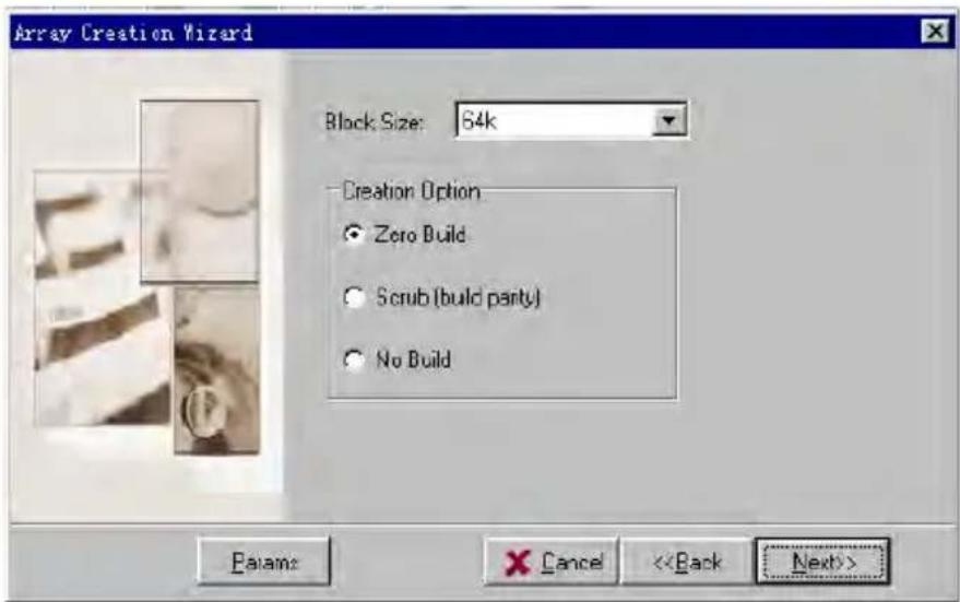
1) Zero Build
Create and initialize data blocks with zero build parities - this will create the array and initialize parity, but will delete all data from each of the hard disks. Use this option when starting from scratch.
2) Scrub (build parity)
This will create an array and initialize parity using the existing data on the hard disks.
3) No Build
Create only - the parity function will not become active until the array is first used.
Step 4:
Select the array disks
Select the single disks from the Available Disks list, and add them to the Selected Disks list using the ( → ) button.
If you are creating a RAID 1 array, and have selected the Create and Duplicate option, the disk which you select first will be the Source disk, and the disk you select second will be the Mirror disk. Please make sure the size of Source disk bigger than Mirror disk. If the size of Source disk bigger than Mirror disk, the following window will appear.
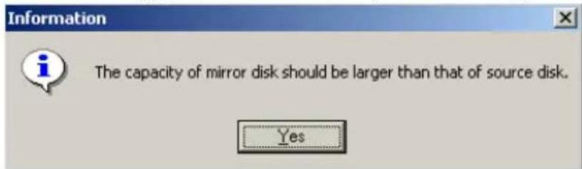
Press OK to select Mirror disk again.
If you are creating a RAID 1 array, and have selected the Create Only option, the source disk will be automatically selected for you.
After selecting the required disks, click on the Finish button to create the array.
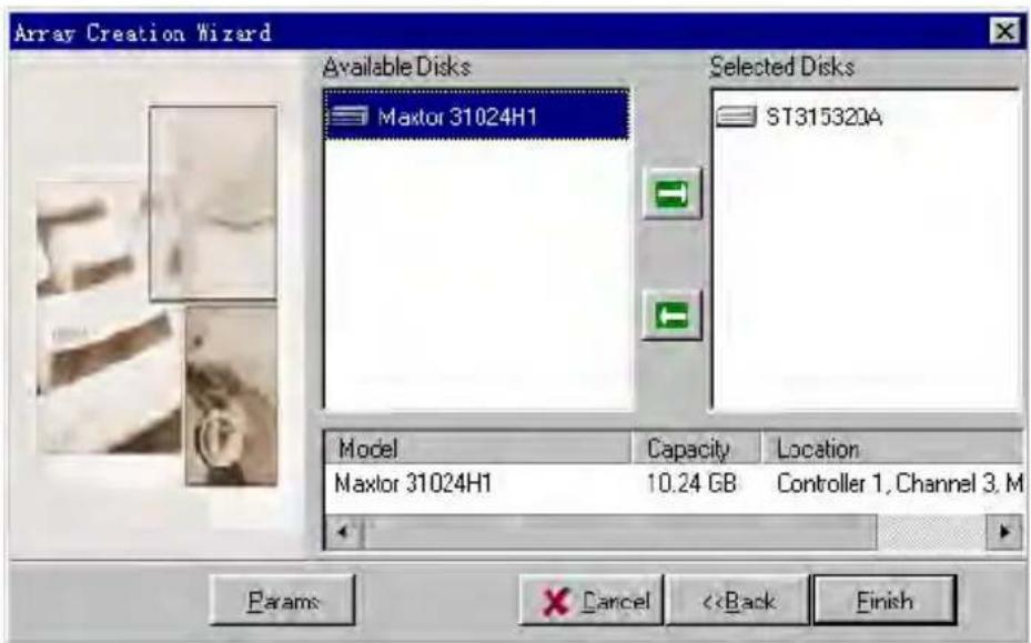
- Deleting an Array
Click on the Management tab, then select the Array Management option from the menu. Select the array you wish to delete from the tree display, and click on the Delete button found on the toolbar. You can also click on the Operation tab, and select the Delete option. A warning message will be displayed. See the following page:  Click Y to delete the selected array, or click N to cancel the operation. Note: You can not delete arrays that are bootable or are in the process of being duplicated, initialized, rebuilt or verified.●Adding a Disk to an Array
Click on the Management tab, then select the Array Management option from the menu. If an array is broken, you will have to add a new single disk to proceed with a rebuild. Select the broken array, then click on the Add Disk button on the toolbar. You can also click on the Operation tab, and select the Add Disk option. If this menu option is disabled, then disks cannot be added to this particular array, or the Add Disk Privilege has not been enabled. When booting the computer, if one member disk of RAID 1, RAID 1/0 or RAID 5 array is broken, and there is a spare disk can be used to rebuild the broken array, system will automatically use the spare disk to rebuild the broken array and then replace data to the target disk, see below:  Press the OK button to rebuild the broken array, press Cancel to exit. If you press the OK button, the following window will appear, see the following page:  Click OK to start the rebuild process, see below.  When the system detects a physical disk, a dialogue box will appear. Select a single disk from the list, and add it to the broken array. Continue to add disks to the broken array until the "broken" status changes. Once the status has changed, the system will begin the auto-rebuild process. When the rebuild procedure is complete, please restart the computer.- Verifying an Array
Click on the Management tab, then select the Array Management option from the menu. Select the array you wish to verify, and click on the Verify button. You can also click on the Operation tab, and select the verify option. Once the verify command has been executed, refresh the software interface - a progress bar should appear. If this menu option is disabled, then the array cannot be verified, or the Verify Disk Privilege has not been enabled. To abort the procedure, click on the Operation tab, and select the Abort option. This will cancel the Verify procedure.● Rebuilding an Array
Click on the Management tab, then select the Device Management option from the menu. Highlight the array that needs to be rebuilt, and click on the Rebuild Array button. Broken RAID 5, RAID 1, or a sub-RAID 1 of a RAID 10 array can use this feature. If this menu option is disabled, then array cannot be rebuilt, or the Rebuild Array Privilege has not been enabled. To abort the procedure, click on the Operation tab, and select the Abort option. This will cancel the Rebuild procedure.● Rescanning Devices
Click on the Management tab, then select the Device Management option from the menu. Click on the Rescan Device button, or click on the Operation tab, and select the Rescan Devices option. This will scan all of the physical devices attached to the RAID controller.3. Spare Pool
Click on the Management tab, then select the Device Management option from the menu. Click on the Spare Pool button - this will open a new window. See the image below: - Assign a disk to the spare pool
If you need to assign a spare disk to an important array, select the Assign to Dedicated Array option. Disk arrays that can utilize the spare feature will be then be displayed, and listed on the drop-down menu towards the right hand side of the array list. When an array is selected, the Available Disks list section will display all the single, physical disks attached to the RAID controller. The Array Spares list will display the physical disks that have already been set to act as spare disks. The procedure can be repeated to add or remove additional spare disks.4. Event Notification
Click on the Management tab, then select the Event Notification item from the menu. The E-mail Notification window will appear. When an event occurs, the system will send an E-mail to the preset mailboxes.●E-mail notification setting
In order to send and receive email, you must first configure the SMTP server. Click the Settings button on the toolbar, or click on the Operation tab and select the Settings option. The E-mail notification-setting window will be displayed. See the image below:  Check the Enable E-mail option, and fill out the Mail From, SMTP server, and Port fields with the appropriate information. Click OK to complete this procedure. The system does not support user-validated SMTP server.- Add Recipient
Click on the Add button found on the toolbar, or click on the Operation tab and select the Add Recipient option. This will open the Add Recipient window. See the following page:  Enter an e-mail address, the recipient's name, and the notification options. Three types of e-mail notification options are available: Information, Warning, and Error. You can enable any number of these options. Click OK to confirm your selections.- Modify Recipient
Click on the Modify button located on the toolbar, or click on the Operation tab and select the Modify Recipient option. This will open the Modify Recipient window. Modify the desired fields, and click OK to confirm your selections.Delete Recipient
Highlight a recipient, and click on the Delete button found on the toolbar, or click on the Operation tab and select the Delete Recipient option. This will open the Delete Recipient window. A warning message will be displayed. Click OK to delete the recipient.5. Task Management
Click on the Management tab, then select the Task Schedule Management item from the menu. The following window will be displayed:  When an array needs to be regularly verified or rebuilt, you can create a new scheduled task to automatically manage this procedure. The Task Schedule list displays information about all added tasks. Double click one of the task entries, or select one and click on the Details button to display detailed information about the selected task. If the appropriate Privileges have been enabled, you can add new tasks, and modify or delete existing tasks.- Adding a Task Schedule
There are two types of tasks that can be scheduled: Verify Array, or Rebuild Array. If any arrays can be rebuild in the current system, click on the New button located on the toolbar to open the New Task Schedule Wizard. See the image below:  Select the task type, and the target array from the drop-down menu. Then, click on the Next button to continue. 2. Icon View
Click the View tab, and select the Icon View option from the menu. A new window will be displayed which shows the various event icons and their descriptions. Chapter 5
Trouble Shooting
Please refer to this chapter if you encounter any problems while using the RocketRAID 1640. It provides answers to the most frequently asked questions, and solutions to some of the more common problems associated with the host adapter. HighPoint1. The RocketRAID 1640 adapter is not recognized by the computer after inserting it into the PCI slot.
If the card is detected by the system the following screen will be displayed when the computer is starting up:  If the above screen does not appear, the adapter is not recognized by the system. Open the computer's chassis, and check for the following: 1) Whether or not the adapter has been securely installed into the PCI slot. 2) If necessary, try using another PCI slot. After securing the adapter, replace the computer case and power on the system.2. The hard disk connected to adapter can not be detected out.
After the RocketRAID 1640 adapter is recognized by the system, the adapter's BIOS will start to scan for hard disk drives. If drives are detected, the following information will be displayed:  Please pay close attention to the information displayed by the BIOS - make sure all of the hard disks attached to the controller are recognized by the BIOS. If one or more of the hard disks are not recognized, open the computer's chassis and check for the following: 1) Make sure the power cable for the hard drive is securely attached. If necessary, try using another power cable. 2) Make sure the cable is securely attached to the hard disk. If necessary, try using another cable. After checked the above, please place the cover of computer chassis and power on the computer.3. Hard disk mode is not correctly recognized.
In order to boot from disk or disk array connected to adapter, usually you should do the following: 1. Set SCSI device as the first-booting device in main board BIOS; 2. Set a booting device in RocketRAID 1640 adapter BIOS (refer Chapter 3 on how to set a boot device). Note: If the regular IDE hard disks are chosen, by using the RocketHead 100 converter connect to RocketRAID 1640, please make sure the hard disks jumper must correctly set to the master position.4. What should I do if an array is reported as broken?
If an array is reported a broken, shutdown the system and make sure the power and IDE cables are securely attached to the hard disks. If necessary, change the cables, then power on the system. If the problem was related to a connection issue, this may restore the array. If the method described above does not work, the broken array was likely caused by a hard disk error, or malfunction. For RAID 1, 10, or 5 arrays, a new hard disk can be used to rebuild the broken array - data will not be lost. For RAID 0 or JBOD arrays, the array must be deleted, and recreated - all data on the array will be lost. Please make sure to backup all important data stored on RAID 0 or JBOD arrays.Appendix A Glossary
Array
Also known as Disk Array, two or more hard disks combined together to appear as a single device to the host computer.RAID
Redundant Array of Independent Disks, it is a method of combining several hard disks (physical disks) into one logical unit (logical disk), thus providing higher performance and data redundancy.RAID Levels
RAID levels refer to different array architectures (or methods of organizing a disk array). Different RAID levels represent different performance level, security level and cost.Striping
Known as RAID 0, spread data over multiple disks to improve performance. It does not provide data protection.Mirroring
Known as RAID 1, which provides data protection by real-time and automatic duplicating all data from a source disk to a mirror disk.RAID 1/0
It is the combination of RAID 1 and RAID 0.RAID 5
RAID 5 includes a rotating parity array, thus, all read and write operations can be overlapped. RAID 5 stores parity information but not redundant data. It requires at least three disks to provide the most economic way to maximize data capacity with faster transfer rate.JBOD
JBOD is an acronym for Just a Bunch of Disks. It is used to refer to hard disks that aren't configured according to RAID a subsystem of disk drives that improves performance and fault tolerance. JBOD provides much more capacity (the sum of all the disks). If there is more than a single physical disk (not member of an array and not an ATAPI device or a removable disk), you can create a JBOD array.Serial ATA
Serial ATA is an evolutionary replacement for the IDE ATA physical storage interface. Serial ATA is scalable and will allow future enhancements to the computing platform.Broken Array
Disk array with a member disk failed. A broken RAID 1, RAID 5 or RAID 1/0 array can still function with the remained normal disks, but a broken RAID 0 or JBOD will no longer function.Rebuild
The ability to use a new disk to replace the failed disk in a redundant disk array (say mirror array, 1/0 array or 5 array), then to repair the broken disk array and recover all the data on that failed disk.Duplicate
The operation of duplicating user data to generate backup data within a RAID 1 array. Also known as Synchronize.Spare Disk
A spare hard disk which can automatically be used to replace the failed member of a redundant disk array and then automatically recover the redundant disk array without intervention.Spare Pool
Logically the place where spare disks stay. When a disk is added into the spare pool, it will become a spare disk.Synchronize
Same as Duplicate.Appendix B
Contact Technical Support
If you encounter any problems or have any questions about the product, please make sure to read through the manual. Additional information about HighPoint products is available from our web site: http://www.highpoint-tech.com If the information provided by the manual and our web site are unable to answer your questions or solve the problem, please contact our Technical Support department: E-mail address: support@highpoint-tech.com Thank you for choosing our products!FCC Part 15 Class B Radio Frequency Interference Statement
This equipment has been tested and found to comply with the limits for a Class B digital device, pursuant to part 15 of the FCC Rules. These limits are designed to provide reasonable protection against harmful interference in a residential installation. This equipment generates, uses and can radiate radio frequency energy and, if not installed and used in accordance with the instructions, may cause harmful interference to radio communications. However, there is no guarantee that interference will not occur in a particular installation. If this equipment does cause harmful interference to radio or television reception, which can be determined by turning the equipment off and on, the user is encouraged to try to correct the interference by one or more of the following measures: - Reorient or relocate the receiving antenna. - Increase the separation between the equipment and receiver. - Connect the equipment into an outlet on a circuit different from that to which the receiver is connected. - Consult the dealer or an experienced radio/TV technician for help. Modifications not expressly approved by the manufacturer could void the user's authority to operate the equipment under FCC rules. This device complies with part 15 of the FCC Rules. Operation is subject to the following two conditions: (1) this device may not cause harmful interference, and (2) this device must accept any interference received, including interference that may cause undesired operation.European Union Compliance Statement
This Information Technology Equipment has been tested and found to comply with the following European directives: • European Standard EN55022 (1998) Class B • European Standard EN55024 (1998)- Trademarks
- Notice
- Table of Contents
- Chapter 1
- Introduction
- Chapter 2
- Adapter Installation
- Chapter 3
- BIOS Configuration
- Chapter 4
- RAID Administrator
- Chapter 5 Trouble Shooting
- Chapter 1 Introduction
- Serial ATA Overview
- RAID Basics
- RocketRAID 1640
- Serial ATA RAID Function and High Performance
- Thin, unrestrictive Cable Design is easy to Configure, and improves Chassis Cooling
- IDE Hard Disk Compatible
- Adapter Layout
- Adapter Installation
- Note:
- Verifying the Adapter's Installation
- Driver Installation
- ● Windows 9x/ME
- Installation
- Verify Installation
- - Windows NT4.0
- Installing the RocketRAID 1640 driver during Windows NT 4.0 installation
- ● Windows 2000
- Installing the RocketRAID 1640 driver for an existing Windows 2000 system
- Installing the RocketRAID 1640 driver during Windows 2000 installation
- - Windows XP
- Installing the RocketRAID 1640 driver for an existing Windows XP system
- Installing the RocketRAID 1640 driver during Windows XP installation
- BIOS Configuration Utility
- Entering the BIOS Configuration Utility
- Creating a Disk Array
- Warning:
- Deleting Disk Arrays
- Add/Remove Spare
- Settings
- View
- Duplicate Critical RAID 1 array
- Rebuilding a Broken RAID array
- Power off
- Destroy
- Continue
- Rebuild
- Chapter 4 ATA RAID Software
- Introduction
- Installation
- Getting Started
- Starting the Management Service
- Starting the Management Console
- Using the Software
- The File tab
- Remote Control
- - Adding a Connection
- ● Modifying a Connection
- - Deleting a Connection
- - Connect to a Remote System
- ● Disconnecting a Remote System
- Remote Server Configuration
- - System Port
- Event Port
- User Management
- - Adding a user
- - Deleting a User
- - Set a User Password
- ●Changing a User's Password
- ● Changing a User's Privilege level
- ● The Management tab
- Array Management
- - Creating an Array
- Step 1:
- Step 2:
- 1) Create Only
- 2) Create and Duplicate
- Step 3:
- 1) Zero Build
- 2) Scrub (build parity)
- 3) No Build
- Step 4:
- ●Renaming an Array
- - Deleting an Array
- ●Adding a Disk to an Array
- - Verifying an Array
- ● Rebuilding an Array
- ● Rescanning Devices
- Spare Pool
- - Assign a disk to the spare pool
- Event Notification
- ●E-mail notification setting
- - Add Recipient
- - Modify Recipient
- Delete Recipient
- Task Management
- - Adding a Task Schedule
- ●To add a new task:
- - Modify Task Schedule
- - Delete Task Schedule
- The View tab
- Event View
- Icon View
- Chapter 5
- Trouble Shooting
- The RocketRAID 1640 adapter is not recognized by the computer after inserting it into the PCI slot.
- The hard disk connected to adapter can not be detected out.
- Hard disk mode is not correctly recognized.
- What should I do if an array is reported as broken?
- Appendix A Glossary
- Array
- RAID
- RAID Levels
- Striping
- Mirroring
- RAID 1/0
- RAID 5
- JBOD
- Serial ATA
- Broken Array
- Rebuild
- Duplicate
- Spare Disk
- Spare Pool
- Synchronize
- Appendix B
- Contact Technical Support
- FCC Part 15 Class B Radio Frequency Interference Statement
- European Union Compliance Statement
Brand : Highpoint
Model : RocketRAID 1640
Category : NAS