
MDM-X4 - Dictaphone SONY - Free user manual and instructions
Find the device manual for free MDM-X4 SONY in PDF.

| Product Type | MD Multitrack Recorder/Mixer |
| Brand | Sony |
| Model | MDM-X4 |
| Power Supply | 120 V / 230 V, 50/60 Hz ; 25 W (120 V) / 27 W (230 V) |
| Number of Tracks | 4 (max 4 simultaneous with MD-DATA, 2 with MD audio) |
| Recording Medium | MiniDisc (MD-DATA and MD audio) |
| Maximum Recording Time | 37 min (4 tracks), 74 min (2 tracks), 148 min (1 track) |
| Sampling Frequency | 44.1 kHz |
| Frequency Response | 5 – 20,000 Hz ±1.0 dB |
| Signal-to-Noise Ratio | >94 dB playback |
| Pitch Control | ±8.0% in 0.25% steps |
| Maximum Number of Songs | 255 |
| Inputs | 6 channels: CH1-4 combo XLR/Jack (balanced/unbalanced), CH5-6 Jack (unbalanced); 2 returns (RETURN 1/2) Jack |
| Outputs | Stereo (RCA), Monitoring (RCA), TRACK 1-4 (Jack), AUX 1/2 (Jack), headphone (Jack) |
| Equalizer | 3-band (HIGH, MID, LOW) on CH1-4; 2-band (HIGH, LOW) on CH5/6 |
| MIDI | IN, OUT, THRU ; supports MTC, MMC, MIDI Clock |
| Assignable Pedals | 2 jacks (ASSIGN SW1, SW2) |
| Dimensions (approx.) | 482 x 300 x 100 mm (width x depth x height) |
| Weight (approx.) | 8 kg |
| Cleaning | Soft cloth slightly dampened with mild detergent; avoid solvents |
| Safety | Do not expose to rain/moisture; disconnect before maintenance; use of class 1 laser |
Frequently Asked Questions - MDM-X4 SONY
User questions about MDM-X4 SONY
0 question about this device. Answer the ones you know or ask your own.
Ask a new question about this device
Download the instructions for your Dictaphone in PDF format for free! Find your manual MDM-X4 - SONY and take your electronic device back in hand. On this page are published all the documents necessary for the use of your device. MDM-X4 by SONY.
USER MANUAL MDM-X4 SONY
MD Multi-Track Recorder
Operating Instructions
Mode d'emploi
Bedienungsanleitung
EN
F
D

DATA

MDM-X4
WARNING
To prevent fire or shock hazard, do not expose the unit to rain or moisture.


This symbol is intended to alert the user to the presence of uninsulated "dangerous voltage" within the product's enclosure that may be of sufficient magnitude to constitute a risk of electric shock to persons.

This symbol is intended to alert the user to the presence of important operating and maintenance (servicing) instructions in the literature accompanying the appliance.
To avoid electrical shock, do not open the cabinet. Refer servicing to qualified personnel only.
Do not install the appliance in a confined space, such as a bookcase or built-in cabinet because the mains power switch (MAIN POWER) is located on the rear panel.
This appliance is classified as a CLASS 1 LASER product. The CLASS 1 LASER PRODUCT MARKING is located on the rear exterior.
INFORMATION
This equipment has been tested and found to comply with the limits for a Class B digital device, pursuant to Part 15 of the FCC Rules.
These limits are designed to provide reasonable protection against harmful interference in a residential installation. This equipment generates, uses, and can radiate radio frequency energy and, if not installed and used in accordance with the instructions, may cause harmful interference to radio communications. However, there is no guarantee that interference will not occur in a particular installation. If this equipment does cause harmful interference to radio or television reception, which can be determined by turning the equipment off and on, the user is encouraged to try to correct the interference by one or more of the following measures:
- Reorient or relocate the receiving antenna.
- Increase the separation between the equipment and receiver.
- Connect the equipment into an outlet on a circuit different from that to which the receiver is connected.
- Consult the dealer or an experienced radio/TV technician for help.
CAUTION
You are cautioned that any change or modifications not expressly approved in this manual could void your authority to operate this equipment.
Owner's record
The model and serial numbers (name plate) are located on the bottom of the unit. Record the serial number in the space provided below. Refer to them whenever you call upon your Sony dealer regarding this product.
Model No. MDM-X4
Serial No.
For the customers in Canada
This Class B digital apparatus meets all requirements of the Canadian Interference-Causing Equipment Regulations.
TO PREVENT ELECTRIC SHOCK, DO NOT USE THIS POLARIZED AC PLUG WITH AN EXTENSION CORD, RECEPTACLE OR OTHER OUTLET UNLESS THE BLADES CAN BE FULLY INSERTED TO PREVENT BLADE EXPOSURE.
Precautions
On safety
- Caution - The use of optical instruments with this product will increase eye hazard.
- Should any liquid or solid object fall into the unit, unplug the unit and have the unit checked by qualified personnel before operating it any further.
On power sources
- Before operating the unit, be sure that the operating voltage of your unit is identical with that of your local power supply.
- Unplug the unit from the wall outlet if it is not to be used for an extended period of time. To disconnect the cord, pull it out by grasping the plug. Never pull the cord itself.
- AC power cord must be changed only at the qualified service shop.
- The unit is not disconnected from the AC power source (mains) as long as it is connected to the wall outlet, even if the unit itself has been turned off.
On placement
- Place the multi track recorder in a location with adequate ventilation to prevent heat buildup in the multi track recorder.
- Do not place the unit in an inclined position.
- Do not place the unit in locations where it is:
-Extremely hot or cold - Dusty or dirty
- Very humid
- Vibrating
– Subject to direct sunlight.
On cleaning the cabinet
Clean the cabinet, panels and controls with a soft cloth lightly moistened with a mild detergent solution. Do not use any type of abrasive pad, scouring powder or solvent such as alcohol or benzine.
On repacking
Do not throw away the carton and the packing material. This makes an ideal container when transporting the unit. When shipping the unit, repack it as it was packed at the factory.
On operation
- If the multi track recorder is brought directly from a cold to a warm location, or is placed in a very damp room, moisture may condense on the lens inside the MD deck. Should this occur, the system will not operate properly. Remove the MD and leave the system turned on for about an hour until the moisture evaporates.
- When you move the system, take out the disc.
On handling MDs
- Do not open the shutter to expose the MD. Close the shutter immediately if the shutter opens.
- Wipe the disc cartridge with a dry cloth to remove dirt.
- Do not expose the MD to direct sunlight or heat sources such as hot air ducts, nor leave it in a car parked in direct sunlight.
Protecting a recorded MD
To record-protect an MD, slide open the tab at the side of the MD so the tab is concealed.
In this position, the MD cannot be recorded. To record on the MD, slide close the tab.
On requesting repairs
The nameplate is located on the bottom exterior.
If you have any question or problem concerning your unit that is not covered in this manual, please consult your nearest Sony dealer.
About This Manual
The following icon is used in this manual:

Indicates hints and tips for making the task easier.
Welcome!
Thank you for purchasing the Sony MD Multi-Track Recorder. Before operating the unit, please read this manual thoroughly and retain it for future reference.
TABLE OF CONTENTS
Overview of MDM-X4
Standard Recording Procedures....4
Names and Functions of Parts
The Mixer....6
The Recorder 8
The Display 10
Input and Output Jacks 11
Connections and Signal Flow
Connections for Recording....13
Connecting MIDI Equipment 14
MDM-X4 Signal Flow Diagram 14
Monitoring
Monitoring Preparations 15
Monitoring Example 15
Setting Up the Operating Environment
System Settings 17
Changing the Settings 18
Recording
Initial Recording 19
Overdub Recording 20
Auto Punch-In/Out Recording 22
Manual Punch-In/Out Recording 25
Mix Write Recording (Basics) 27
Mix Write Recording (Applied Operations) 28
Editing Part of a Song (Track Edit)
Track Edit Overview 31
Specifying the Locate Points 31
Copying a Part (Track Copy) 33
Moving a Part (Track Move) 34
Switching the Location of 2 Parts (Track Exchange) 35
Erasing a Part (Track Erase) 36
Changing the Construction of a Song (Section Edit)
Section Edit Overview 38
Specifying the Locate Points 38
Moving a Section (Section Move) 39
Switching the Location of 2 Sections (Section Exchange) 40
Inserting Another Section (Section Insert) 41
Deleting a Section (Section Delete) 42
Editing Entire Songs (Song Edit)
Song Edit Overview 43
Copying a Song (Song Copy) 43
Moving a Song (Song Move) 44
Changing the Song Order (Song Exchange)......45
Dividing a Song (Song Divide) 46
Connecting 2 Songs (Song Combine) 47
Deleting a Song (Song Delete) 48
Naming a Song (Song Name) 49
Editing the Entire Disc (Disc Edit)
Overview 50
Erasing the Disc Contents (Disc Erase) 50
Naming the Disc (Disc Name) 51
Synchronization with MIDI Equipment
Advantages of Using MIDI 52
MIDI Synchronization Using MTC 52
MIDI Synchronization Using the MIDI Clock 53
Controlling This Unit from Other MIDI Components Using MMC 55
Example of a MIDI System 56
Mixdown
Mixdown (Basics) 57
Mixdown (Applied Operations) 58
Additional Information
Troubleshooting 60
Display Message List....60
System Limitations of MDs 61
Specifications 61
Glossary 63
Block Diagram 64
MIDI Implementation Chart 65
Track Sheet Back Cover
Standard Recording Procedures
The MDM-X4 is an integrated multichannel recorder/mixer that can record up to 4 tracks using MD-DATA discs. In addition to 4 track recording and playback, this unit can also perform a variety of editing operations.
1 Connect instruments, microphones, effectors, (etc.) and prepare for recording.
See “Connections and Signal Flow” (page 13) for details.

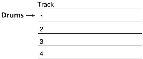
2 Record the first track.
Example : Record the drums to track 1. See “Initial Recording” (page 19) for details.

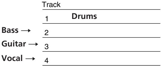
3 Record another instrument on a different track while listening to the previously recorded track.
Example: Record the bass to track 2, the guitar to track 3 and the vocals on track 4. See “Overdub Recording” (page 20) for details.
other
| Instrument | Track | Drums | |---|---|---| | Bass → | 1 | 0 | | Guitar → | 2 | 0 | | Vocal → | 3 | 0 | | | 4 | 0 |
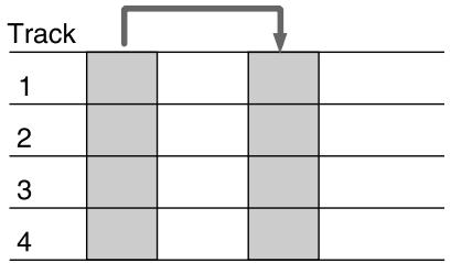
4 You want to add a harmony chorus, but there's no more tracks left!
No problem! If you've already used all 4 tracks, you can record on top of a previously recorded track.
See "Mix Write Recording" (page 27) for details.
| Track | |
| 1 | Drums |
| 2 | Bass |
| 3 | Guitar |
| 4 | Vocal ← Chorus |

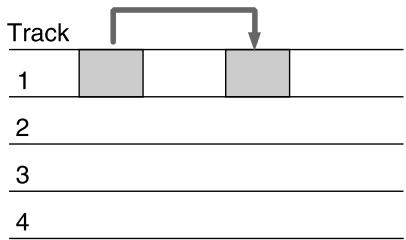
5 You realize that a certain drum fill would sound better in a different place.
You can move, copy, or delete part of the song. For example, if the first and second chorus were reversed, they can easily be switched. See “Editing Part of a Song (Track Edit)” (page 31) for details.
flowchart
graph TD
    A["Track 1"] --> B["Block 1"]
    B --> C["Block 2"]
    C --> D["Down Arrow"]
    style A fill:#ccc,stroke:#333
    style B fill:#ccc,stroke:#333
    style C fill:#ccc,stroke:#333
    style D fill:#ccc,stroke:#333

6 You decide you want to change the structure of the song.
The edit functions let you add (or remove) an extra chorus or repeat the introduction in the middle of the song (etc.) without having to rerecord.
See “Changing the Construction of a Song (Section Edit)” (page 38) for details.
flowchart
graph TD
    A["1"] --> B["2"]
    B --> C["3"]
    C --> D["4"]
    D --> E["End"]

7 Dub the tracks onto an external MD or DAT deck while using the mixer to adjust the balance.
See "Mixdown" (page 57) for details.

Done!
Other convenient functions
- Equipped with an easy to use Jog/Shuttle dial.
- The Auto Punch-In/Out function lets you rerecord part of a song by enabling the record mode automatically only during the part which you have specified.
See "Auto Punch-In/Out Recording" (page 22) for details.
- The Undo function lets you revert to the previous state when an edit operation doesn't produce the desired effect.
- Synchronization with other MIDI equipment is also possible. In addition to the ability to synchronize this unit with an external sequencer at start-up, you can also remote control this unit from the sequencer (with MMC compatible equipment only).
The synchronization functions also let you make recordings by using a computer or sequencer to mediate sounds from acoustic instruments, like vocals or guitar, recorded on this unit with sounds from other MIDI equipment and sound modules (etc.).
See "Synchronization with MIDI Equipment" (page 52) for details.
- The Pitch Control function enables precise speed control.
See the "SYSTEM key" explanation in "Names and Functions of Parts" (page 9) for details.
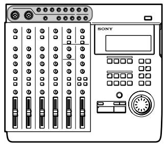
- A 10 INPUT/4 BUS analog mixer with exceptional sound quality.
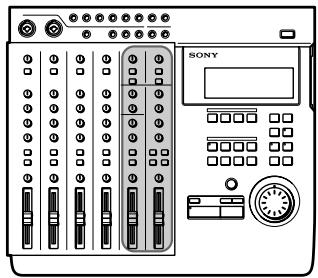
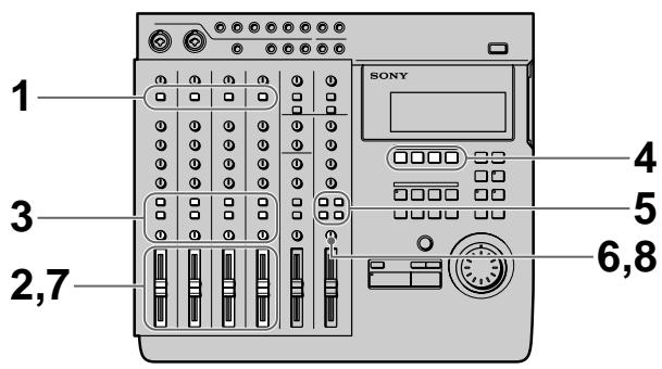
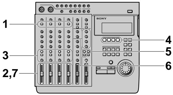
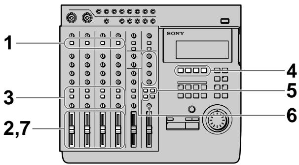
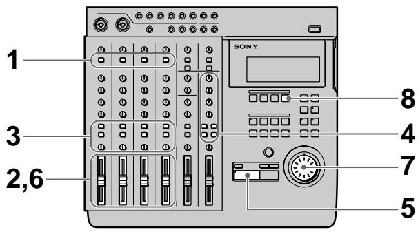
The Mixer
Also refer to the "Block Diagram" on page 64.
The Channel 1\~4 Section
The functions described are the same for each channel (1\~4).

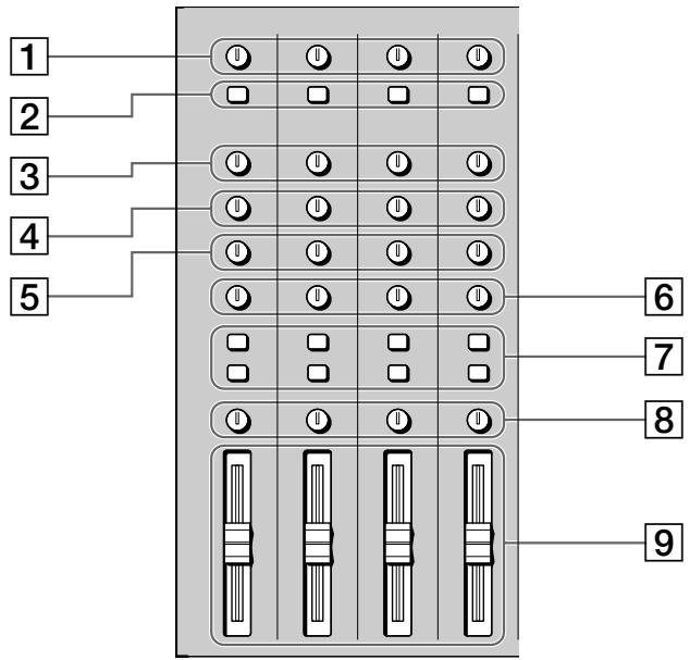
1 TRIM knobs
Allow you to adjust the level of the signals input into the INPUT CH1\~CH4 jacks approximately 40 dB. Turn to the right to increase the input level.
Normally, if you connect an instrument, turn to LINE; if you connect a microphone, turn to MIC.

For the best sound characteristics, adjust the TRIM knob so that the proper level is obtained when the fader is set between 7 and 8.
2 INPUT selector keys
Allow you to select either LINE/MIC (sound from the INPUT CH jacks) or TRACK 1\~4 (sound from the recorder) for input to mixer channels 1\~4.
LINE/MIC : Use to input external sounds from an instrument or microphone (etc.).
TRACK 1\~4 : Use to input sounds played back from the recorder.
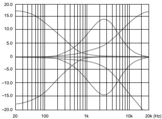
3 HIGH knobs
Adjust the treble of the respective channel. Provide a shelving type equalization.
4 MID knobs
Adjust the middle frequencies of the respective channel. Provide a peak type equalization.
5 LOW knobs
Adjust the bass of the respective channel. Provide a shelving type equalization.
HIGH/MID/LOW equalizer characteristic curves
line
| Frequency (Hz) | Value | | -------------- | ----- | | 20 | 17.0 | | 100 | 15.0 | | 1k | 14.0 | | 10k | 16.0 | | 20k | 17.0 |6 AUX knobs
Adjust the level of the sound sent to the AUX bus (1\~2) from the respective channel. Turn to "1" to output the sound from the respective channel to AUX bus 1. Turn to "2" to output the sound from the respective channel to AUX bus 2.
When set to the center position, no sound is output from either AUX bus.
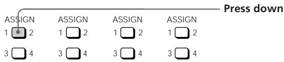
7 ASSIGN keys
Determine which group bus the channels will be assigned to (which track on the recorder they will be recorded to).
The channel signal is always connected to the stereo bus
Example: To assign the sounds from channels 2 and 3 to group bus 1. (To record them to track 1 of the recorder).
8 PAN knobs
Adjust the sound balance of the stereo or group bus. Turn towards “L” to move the sounds toward group bus 1 or 3 and the “L” side of the stereo bus. Turn towards “R” to move the sounds toward group bus 2 or 4 and the “R” side of the stereo bus.
9 Faders 1\~4
Adjust the volume of each channel.
Channel 5,6 and MASTER
1 MASTER AUX 1\~2 knobs
Adjust the master level of the AUX bus sound output from the AUX OUTPUT 1\~2 jacks.
2 HIGH knob
Adjusts the treble of the sound input to the INPUT 5/6 jacks at the top of the unit. Provides a shelving type equalization.
3 LOW knob
Adjusts the bass of the sound input to the INPUT 5/6 jacks at the top of the unit. Provides a shelving type equalization.
4 ASSIGN keys
Determines which group bus the sounds input to the INPUT 5/6 jacks at the top of the unit will be assigned to (which track on the recorder they will be recorded to).
Channel 5 can only be assigned to group bus 1 or 3.
Channel 6 can only be assigned to group bus 2 or 4.
EXAMPLE: To assign the sounds from channels 5 and 6 to group bus 1 and 2 respectively. (To record them to track 1 and 2 of the recorder).
5 BALANCE knob
Adjusts the relative balance of channels 5 and 6.
Rotate toward "L" to increase the volume of channel 5.
Rotate toward "R" to increase the volume of channel 6.
6 Fader 5/6
Simultaneously adjusts the volume of both channels 5 and 6.
7 RETURN knobs (1 and 2)
Adjust the volume of the sound input into the RETURN 1 and 2 jacks at the top of the unit. (Return sound is generally used for adding external effects.)
8 ASSIGN keys
Determine which group bus (1\~4) the return sounds will be assigned to (which track on the recorder they will be recorded to).
Example: To assign the sounds from return 1 and 2 to group bus 1 and 2. (To record them to tracks 1 and 2 on the recorder).
(continued)
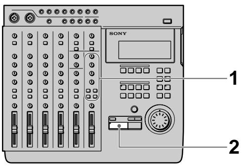
9 TRACK 1\~4 knobs
Use to adjust the overall sound balance when monitoring playback from the recorder (CUE monitor) by turning the knob for each track as desired. When using the CUE monitor function, be sure to press down the monitor track setting CUE key (10 below).
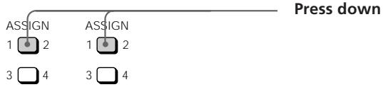
10 Monitor Track Setting keys
Select the sound to be monitored.
1–2 : Press down to monitor the sound from group bus 1 and 2.
3–4 : Press down to monitor the sound from group bus 3 and 4.
CUE : Press down to monitor playback from the recorder. Use the TRACK 1\~4 knobs to adjust volume of the individual tracks.
STEREO : Press down to monitor the sound from the stereo bus.
11 MONITOR knob
Adjusts the volume of the sound output from the MONITOR OUT jacks (on the rear panel) and the HEADPHONES jack (on the front panel).
12 MASTER fader
Adjusts the volume of the stereo bus sound output from the STEREO OUT jacks on the rear panel.
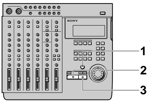
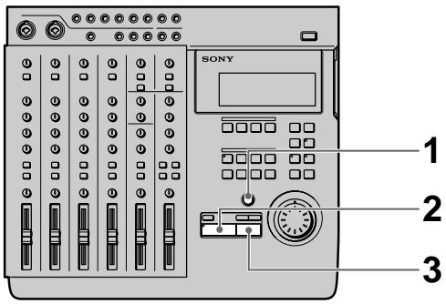
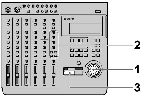
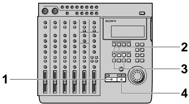
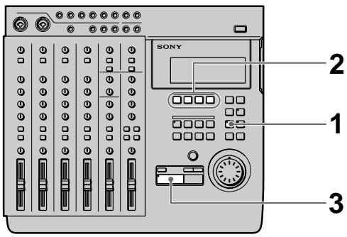
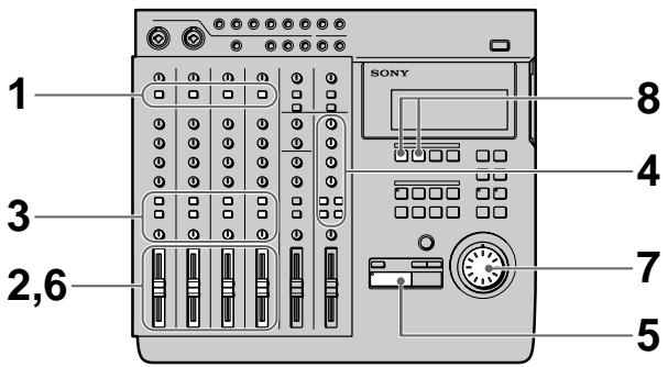
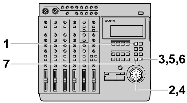
The Recorder
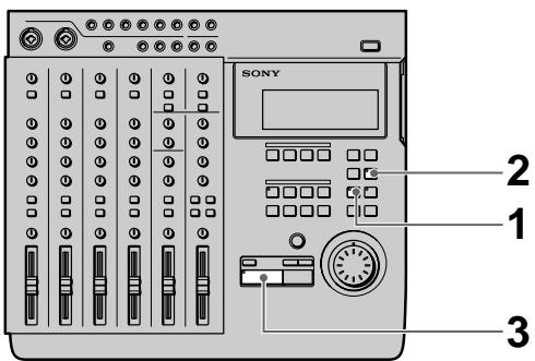
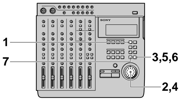
Control Panel
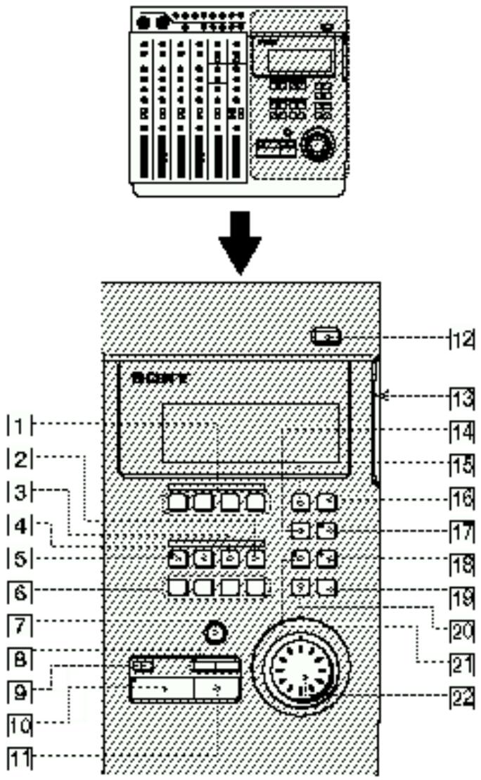
① REC SELECT 1\~4 keys
Press to light the corresponding track indicator(s) and select the track(s) to be recorded. These keys also function as in/out keys during manual punch-in/out recording.
2 SHIFT key
Holding down this key when you press another key lets you carry out the function written below the respective key.
EXAMPLE: The REPEAT key

DISPLAY
- When pressed alone, it functions as the REPEAT key
- When pressed while holding down SHIFT, it functions as the DISPLAY key.
3 OUT key
Sets the out point (edit end point).
4 IN/DEST key
Sets the in point (edit start point).
Press while holding down SHIFT to set the destination point (edit destination point).
5 MARK key
Press to set a mark point (and the key starts blinking). Press IN, OUT, DEST, or A\~H while the MARK key is blinking to set the mark point to the respective key. This unit lets you assign up to 11 mark points using IN, OUT, DEST, and A\~H.
6 Locate point keys
Press to recall mark points. To specify points E\~H, press the respective key while holding down SHIFT.
7 REC key
Press to enter record mode. The key blinks, to indicate record pause mode. The key lights steadily when recording.
8 ◀◀/▶▶ keys
Press to locate the beginning of the previous or next song. When adjusting a mark point, they can also be used with the rehearsal function to switch between a volume increase or decrease after the mark point.
9 TOP key
Press once to locate the beginning of the first song on the disc. Press again during stop mode to locate the beginning of the unrecorded (blank) part of the disc.
10 ▶ PLAY key
Starts playback. Lights during playback.
11 ■ STOP key
Stops recording or playback.
Hold down this key and press the ▶ PLAY key to activate the IN-OUT playback mode and play back the section between the IN and OUT points repeatedly. Pressing this key during stop mode to write the TOC data* to the disc.
12 ≜ EJECT key
Press to remove the disc.
If the TOC data* has not been written to the disc, it will be written automatically before the disc is ejected.
* You must write the TOC data to disc after a SECTION edit, SONG edit, or DISC edit. See pages 38 and 44 for details.
13 Disc insertion slot
Insert the disc into this slot.
14 REPEAT/DISPLAY key
Press to activate the repeat playback mode. The repeat mode changes as follows each time you press the key:
- REPEAT : Repeats all the songs on the disc.
- REPEAT 1: Repeats the current song.
- 1 : Plays the current song once. After playback, the unit locates the beginning of the song.
- (no indicator) : Off. Plays all of the songs on the disc. Press while holding down SHIFT to change the display mode as follows:
- Time Mode: Shows the counter display in time.
- Bar Mode : Shows the counter display in bars.
- Remaining Mode: Shows the amount time which can be recorded remaining on the disc.
Note
Numbers will not be displayed in bar mode, if no tempo information is input.
15 EDIT key
Press to enter Edit mode. Edit mode can only be entered when the disc is in stop mode.
16 SYSTEM key
This key has two functions.
- System setting
Press when making system settings to enter the system settings. See “Changing a Setting” (page 18) for details.
- Pitch Control
Press while holding down SHIFT to turn the recording/playback pitch control “on”. Press again while holding down SHIFT to turn the recording/playback pitch control “off”.
Pitch control “on”: Recording or playback is conducted in the preset pitch. (“Vari Pitch” is displayed.)
Pitch control “off”: Recording or playback is conducted in the normal pitch. (“Fixed Pitch” is displayed.)
See "System Settings" (page 17) for details on the pitch setting.
(continued)
17 RHSL (Rehearsal) key
This key has two functions:
• Record rehearsal (rehearsal function)
Press during record pause mode to cause the indicator to blink and set this unit to operate as if it were recording, without actually recording. This is called rehearsal mode. (Rehearsal mode can also be activated by pressing RHSL when the AUTO PUNCH key is lit.)
During record rehearsal, all other operations will function as if the unit was recording. This provides a convenient way to practice without actually recording.
Press ■ STOP to cancel the rehearsal mode.
Rehearsal mode, however, is not activated when recording a new song.
- Locate point adjustment (locate adjust function)
Press to light the indicator and repeat the section just before and after the current locate point. The repeat time is specified in the roll time setting. Turning the JOG dial during rehearsal lets you adjust the position of the locate point.
Press ■ STOP to cancel the locate adjust mode.
See “Correcting the position of the locate point” (page 32) for details.
Note
During locate adjust mode the counter value does not change to reflect the position of the playback sound.
Use JOG or SHUTTLE to adjust the counter value/position of the respective locate point. However, if you do not register the new value as a mark point it will be erased after the adjustment.
18 UNDO key
Erases the previous edit or auto punch-in/out operation and returns the data to its original status.
See "Using the Undo Function" (pages 24, 31, 38, 43) for details.
19 ENTER key
Press to carry out the selected operation (etc.).
20 EXIT key
Press to cancel the selected operation or to exit the edit mode.
21 AUTO PUNCH key
Use to select the auto punch-in/out function.
22 Jog dial (Jog/Shuttle dial)
Use to search (find a specific point within a song), select items from menus, set parameters, and adjust locate point positions (etc.).
The smallest increment in which a locate point can be adjusted is one click of the jog dial (approx. 11.6 msec).
The Display

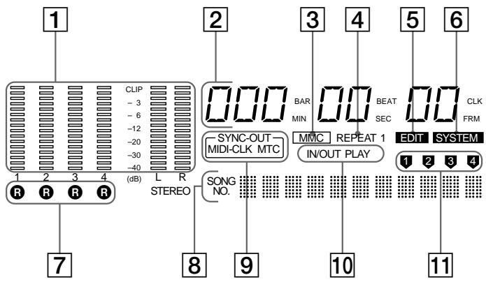
1 Level meters
• 1\~4
During playback : Display the output levels of each track on the disc.
During recording : Display the input levels of the track(s) being recorded.
During stop mode or when no disc is inserted : Displays the volume of group bus 1\~4.
• L, R
Displays the volume of the stereo bus.
2 Counter display
Displays the time (minute/second/frame) or bar (bar/beat/clock).
3 MMC indicator
Lights when the unit can receive MMC (MIDI Machine Control) signals.
4 REPEAT indicator
Light during repeat playback.
"REPEAT" lights when repeating all the songs on the disc, "REPEAT1" lights when repeating one song.
5 EDIT indicator
Lights during edit operations (track, section, song, disc).
6 SYSTEM indicator
Lights during system setting operations.
7 R indicators
Lights to indicate that the respective track was selected for recording using the REC SELECT keys. The track number corresponds to the group bus number.
8 Title display area
Displays the song or disc title, as well as edit menu information.
9 SYNC-OUT indicator
Displays the currently selected output synchronization. See pages 17 and 52\~56 for details.
MIDI-CLK : Lights when the MIDI clock is being output.
MTC : Lights when the MIDI time code is being output.
10 IN/OUT PLAY indicator
Lights during IN/OUT playback.
11 Track display indicator
Displays the source track during editing.
Input and Output Jacks
Top panel

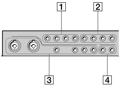
1 TRACK 1\~4 output jacks
Output the sound from tracks 1\~4 of the recorder.
The TRACK 1\~4 jacks output the signals for each track as they were recorded onto the disc.
Previously recorded signals are played back and output, even when the recorder is recording.
2 RETURN 1 / 2 (L (MONO) /R) input jacks
Use to input signals from external sources.
For example, when sending a sound modified by an external effect back to the mixer.
Use the L (MONO) jack when inputting monaural signals.
③ CH 1\~6 input jacks
Use to input sounds to channels 1\~6. The CH 1\~4 jacks are for signals from microphones or line level sources.
The CH 5 and 6 jacks are for line level signals only.
Channel 1 and 2 allow direct connection of XLR type plugs. (Channels 1 and 2 are balanced inputs for both XLR and standard plugs.)
(continued)
4 OUTPUT AUX 1/2 jacks
Output sound for use as the send output. After adding an outboard effect to the sound output from these jacks, use the RETURN 1/2 (L/R) jacks to input it back to this unit.
Rear Panel
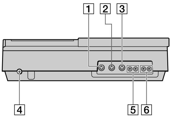
1 MIDI THRU jack
Outputs the same signal input to the MIDI IN jack.
2 MIDI OUT jack
Outputs the MIDI signal. Connect to the MIDI IN jack of another piece of MIDI equipment.
③ MIDI IN jack
Inputs the signals output from the MIDI OUT jack of another piece of MIDI equipment.
4 Power switch
Use to turn the power of this unit on and off.
5 MONITOR OUT jack
Outputs the sound of the monitor bus. Connect to a pair of monitor speakers or an amplifier.
See "Connections for Recording" (page 13) for details.
6 STEREO OUT jack
Outputs the sound of the stereo bus. Connect to a DAT deck (etc.) during mixdown.
See "Connections for Recording" (page 13) for details.
Front Panel
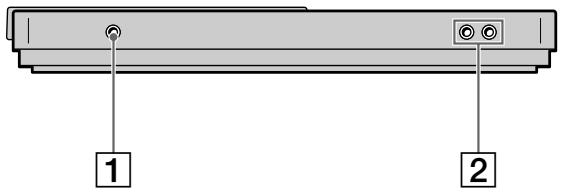
natural_image
Diagram of a device rear panel with labeled ports (no text or symbols beyond labels 1 and 2)1 HEADPHONES jack
Connect a pair of headphones with a standard type plug.
② ASSIGN SW 1,2 jack
For connecting external switches, such as a foot switch (etc.).
See “System Settings” (page 17) for details regarding the functions which can be controlled.
You can use either ↗ or ↘ type foot switches. When the power is turned on, this unit registers the current position of the connected pedal as "OFF".
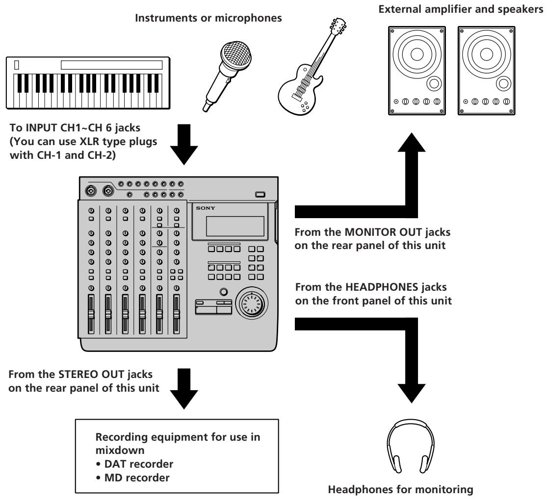
Connections for Recording
Connect instruments, microphones, and amp and headphones for monitoring as shown below.
flowchart
graph TD
    A["Instruments or microphones"] --> B["To INPUT CH1~CH 6 jacks (You can use XLR type plugs with CH-1 and CH-2)"]
    B --> C["Recording equipment for use in mixdown"]
    C --> D["Recording equipment for use in middown"]
    E["External amplifier and speakers"] --> F["From the monitor out jacks on the rear panel of this unit"]
    F --> G["Headphones for monitoring"]
    G --> H["From the headphones jacks on the front panel of this unit"]
    H --> I["From the STEREO OUT jacks on the rear panel of this unit"]

When inputting sound from a sound module into this unit
You can mix the sound with sounds previously recorded on tracks 1\~4 by using the INPUT CH-5 or INPUT CH-6 jacks.
Do the following when connecting an external effector to input the return sound.
To output sound to the effector : Use the AUX 1 or AUX 2 jacks on the top panel of this unit.
To input sound from the effector (return sound): Use the RETURN 1 or RETURN 2 jacks on the top panel of this unit.
Turning on the Power
After you have completed all connections, connect the power cord from this unit to a wall outlet.
Connecting MIDI Equipment
Connect MIDI equipment as shown in the following diagram.
For details regarding connections for synchronized operation with a sequencer (etc.), see “Synchronization with MIDI Equipment” (pages 52\~56).
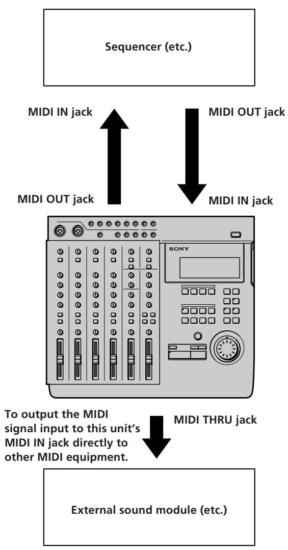
External sound module (etc.)
MDM-X4 Signal Flow Diagram
The following diagram shows the internal signal flow of this unit.
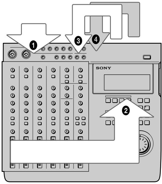
① Input external sounds.
② The input sound is recorded after being mixed and assigned to the respective group bus (1\~4).
③ The playback sound from the recorder is input back into the mixer (mix write recording, bounce recording).
④ The playback sound from the recorder is output to an external component, that adds an effect, before being input back into the mixer (mix write recording, bounce recording).
This unit's 6 channel inputs and 2 stereo return inputs are connected to group bus 1\~4 and stereo bus L/R. (For group bus 1\~4 use the ASSIGN keys to assign the input sound to a group bus. The channel signals are always connected to the stereo bus. In cases where you do not want to mix the signals to the stereo bus, lower the faders for the respective channels to "0".)
When monitoring, you can select group bus 1-2, group bus 3-4, stereo bus, or TRACK 1\~4 OUTPUT (CUE bus).
For details on how to monitor, see “Monitoring Example” (page 15).
Monitoring Preparations
This unit enables you to monitor the following 4 types of signals as necessary.
① Group 1, 2: Select to monitor mixer group bus 1 and 2. The sound from group bus 1 is localized in the L (left) channel and the sound from group bus 2 is localized in the R (right) channel. When recording, select to monitor the sound being recorded.
② Group 3, 4 : Select to monitor mixer group bus 3 and 4. The sound from group bus 3 is localized in the L (left) channel and the sound from group bus 4 is localized in the R (right) channel. When recording, select to monitor the sound being recorded.
③ CUE : Select to listen to all the sound recorded on the disc. You can adjust the volume level of the individual tracks using the TRACK 1\~4 knobs located above the MONITOR keys. (All tracks are heard in mono.) When recording, the track being recorded is muted.
④ STEREO : Select to listen to the sound of the mixer's stereo bus. For use during mixdown (etc.).
Monitoring Example
EXAMPLE 1: Monitoring the sound from group bus 1 and 2 (during recording, etc.)
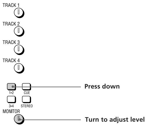
EXAMPLE 2: Monitoring the sound being recorded to tracks 3 and 4 while monitoring the sound of tracks 1 and 2 (during overdubbing, etc.)
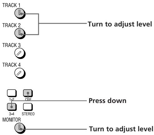
flowchart
graph TD
    A["TRACK 1"] --> B["Turn to adjust level"]
    C["TRACK 2"] --> B
    D["TRACK 3"] --> E["Press down"]
    F["TRACK 4"] --> E
    G["MONITOR"] --> H["Turn to adjust level"]
    I["1-2"] --> J["CLIF"]
    K["3-4"] --> L["STEREO"]
(continued)
EXAMPLE 3: Rerecording part of track 1 while monitoring the sound of tracks 3 and 4 (during punch-in/out recording, etc.)
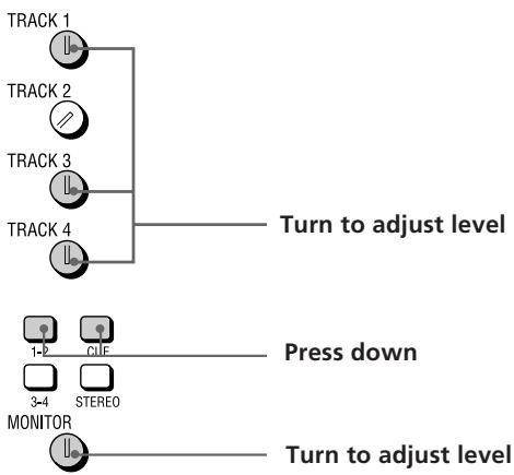
flowchart
graph TD
    A["TRACK 1"] --> B["Turn to adjust level"]
    C["TRACK 2"] --> B
    D["TRACK 3"] --> B
    E["TRACK 4"] --> B
    F["1-P"] --> G["Press down"]
    H["3-4"] --> I["STREEO"]
    J["MONITOR"] --> K["Turn to adjust level"]
EXAMPLE 4: Mixing tracks 1\~4 for recording onto tracks 1 and 2 (during mix write recording, etc.)
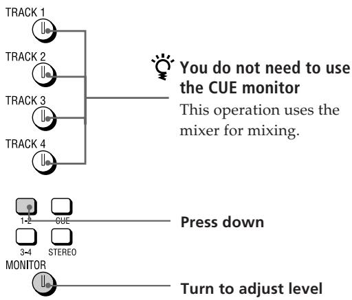
flowchart
graph TD
    A["TRACK 1"] --> B["TRACK 2"]
    B --> C["TRACK 3"]
    C --> D["TRACK 4"]
    D --> E["MONITOR"]
    style A fill:#f9f,stroke:#333
    style B fill:#f9f,stroke:#333
    style C fill:#f9f,stroke:#333
    style D fill:#f9f,stroke:#333
    style E fill:#ccf,stroke:#333
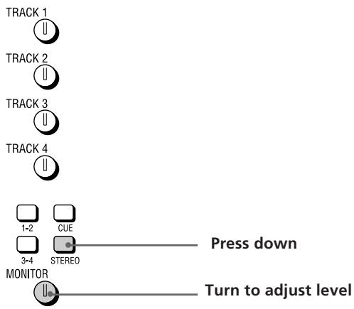
EXAMPLE 5: Monitoring the sound of the stereo bus (for mixdown, etc.)
System Settings
You customize the operating environment by turning the MIDI synchronization and UNDO (undo last operation) functions (etc.) on or off.
Pitch setting (Pitch)
You can set the pitch in 0.25% increments within a range of ±8%. When you turn the pitch control on after setting the pitch, recording/playback is conducted at the selected pitch.
See the “System key” in “Names and Functions of Parts” (page 9) for details on turning the pitch control on/off.
MMC setting (MMC)
This sets the MMC (MIDI Machine Control) reception.
See page 55 for details about MMC.
off: No reception. Use this setting when using this unit by itself.
on : The unit operates according to the received MMC signals.
Device ID setting (Dev ID)
Sets the MMC ID number. It can be set to any number between 0 and 126. When this unit receives ID = 127 signals, they are registered as a valid signals regardless of this unit's ID setting.
Synchronized output source setting (Sync)
Sets the Synchronized output source. See pages 52 and 53 for details about synchronization.
off : Does not output a synchronization signal
MTC (MIDI Time Code) : When using the MTC for synchronization.
MCLK (MIDI Clock) : When using the MIDI clock for synchronization.
MTC frame number setting (Frame)
Sets the MTC frame number (per second). You can select either 25 or 30 non-drop frames.
Assignable switch 1, 2 setting (Sw-1, Sw-2)
Allows you to assign one of the following commands for control by the external switch connected to the ASSIGN SW1 or SW2 jack on the front panel.
Play : Same function as this unit's ▶ PLAY key.
RecIO : Press once for the same function as the REC key (punch-in). Press again for the same function as the ▶ PLAY key (punch-out). This setting allows you to conduct punch in-out recording from an external switch.
Stop : Stops the disc operation.
IOply (In-Out Play) : Starts IN-OUT playback
PlayS (Play-Stop) : Press one to start playback, press again to stop playback.
Rec S (Rec-Stop) : Press once to start recording, press again to stop recording.
Pre-roll/Post-roll setting (Roll)
Allows you to set the pre-roll/post-roll time used during rehearsal (locate point adjustment) and auto punch-in/out operations in 1 second increments. It is adjustable from 1 to 10 seconds.
Undo function on/off setting (Undo)
This determines whether the undo function will be on or off when you use auto punch-in/out. During edit mode, however, the undo function is always on.
Changing this setting also changes the redo function (that allows you to undo the undo) setting is also changed at the same time.
Disabl (off) : Turns off the undo function
Enabl (on) : Turns on the undo function
The indicator on the UNDO key has the following meanings:
GREEN : You can use the undo function.
(blinking): Preparing to carry out the undo function.
RED : Undo (or Redo) has been carried out.
(off) : You cannot use the undo function (such as when the previous operation cannot be undone (etc.)).
See page 24 for details about using the undo function with the auto punch-in/out function.
Note
Do to the limitations of this system, if the blank space on the disc becomes too small it may not be possible to use the undo function even if it is set to “on”. In this case, the indicator on the UNDO key will be off. Be sure to check whether this indicator is on or off before performing an edit operations.
Recordable track number setting (Rec)
This sets the number of tracks to be used on the disc. The number of tracks selected is effective the next time a song is recorded. During playback, the number of tracks is selected automatically according to the source disc.
The selectable tracks also differ depending on the type of disc you use (MD DATA or music MD).
| Rec Mode | Usable tracks | Recording time | Usable Discs |
| 4 | 1~4 | 37 min. | MD DATA |
| 2 | 1, 2 | 74 min. | MD DATA, Music MD |
| 1 | 1 | 148 min. | MD DATA, Music MD |
Note
The Rec Mode automatically switches to 2 track for music MDs (even if it was previously set to the 4 track mode).
After recording on a music MD, be sure to reset the Rec Mode to 4 track when you want to make a 4 track recording using a MD DATA disc.
(continued)
Rehearsal mode setting (RHSL)
This setting lets you determine whether the volume will increase or decrease after the locate point when adjusting the position of a locate point with the rehearsal function. See page 32 for details about locate point adjustment.
↑: the volume increases past the locate point.
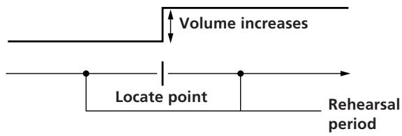
↓: the volume decreases past the locate point.
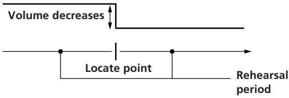

During rehearsal mode, press the ◀◀ or ▶▶▶ key to switch between increased or decreased volume after the locate point.
Display brightness setting (Dimmer)
Adjusts the display brightness. You can choose from 8 levels (1\~8). Larger numbers provide a brighter display.
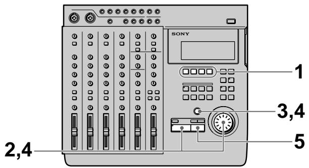
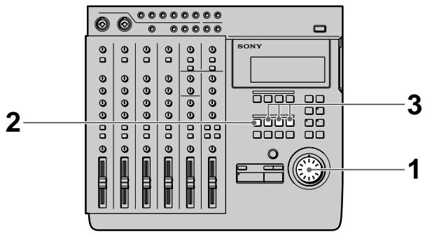
Changing a Setting
Use the following operations to change the system settings
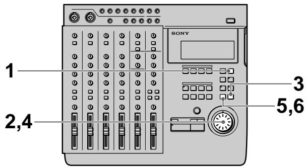
1 Press SYSTEM.
SYSTEM appears in the display.
2 Turn the jog dial to display the item you want to adjust.
The item blinks in the display.
3 Press ENTER.
The blinking moves to the right of the item.
4 Turn the jog dial to display the setting you desire.
5 Press EXIT.
The item starts blinking again.
6 Press EXIT again.
SYSTEM disappears from the display.
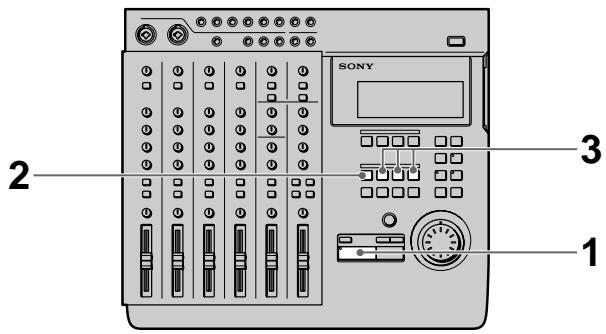
To reset this unit to the original factory settings
1 Turn off the power to this unit.
2 Hold down SYSTEM while turning the power back on.
The power comes on and "Initialized" appears in the display. The system settings are reset to the original factory settings.
Initial Recording
This shows you how to record the very first track onto a blank disc.
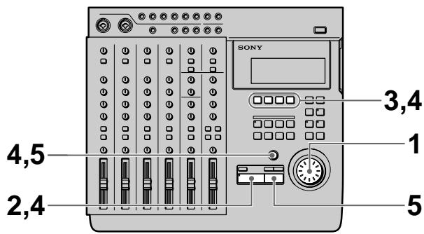
Preparations
1 Set the INPUT switch for the channel to which you will input the instrument or microphone sound to LINE/MIC (up position).
2 Set the fader for the channel to which you will input the sound to about 7 or 8.
3 Use the ASSIGN switch and PAN knobs to direct the sound to the group path you want to record.
EXAMPLE: To assign channel 1 to group path 1
4 Press the REC SELECT key corresponding to the group path number you selected in step 3 to specify the track to be recorded.
5 Press the monitor track set key corresponding to the group path number you selected in step 3.
6 Turn the MONITOR knob to adjust the sound to a level which can be monitored.
7 Use the fader to adjust the recording level.
Play a relatively loud phrase and make adjustments by watching the level meter for the track you want to record.
If necessary, you can use the TRIM knob to adjust the recording level and equalizer.
Adjust the recording level so that the CLIP indicator does not light.
Adjust the TRIM knob so that the proper level is obtained when the fader is set between 7 and 8 to achieve good frequency characteristics.
8 Turn the MONITOR knob as in step 6 to adjust monitor level.
Recording
1 Press REC.
The unit switches to record pause mode.
2 Press ▶ PLAY.
Recording begins
3 When you've finished playing, press ■ STOP.
This unit automatically goes to the beginning of the recorded song.
It takes a few seconds for the unit to process the information after pressing ■ STOP.
Please note that the length of the song is fixed at the point where the initial recording ends.
Note
Do not turn off the power during recording. Not only may you loose the data for the current song, you may loose all of the data on the disc.
(continued)
Checking the Recording
1 Press CUE to prepare for monitoring.
Adjust the monitor volume using the respective TRACK knobs and the MONITOR knob.
2 Press ▶ PLAY.
Playback begins.
If necessary, you can use the jog dial to locate a specific point.
To rerecord
Follow the "Recording" procedure on the previous page.
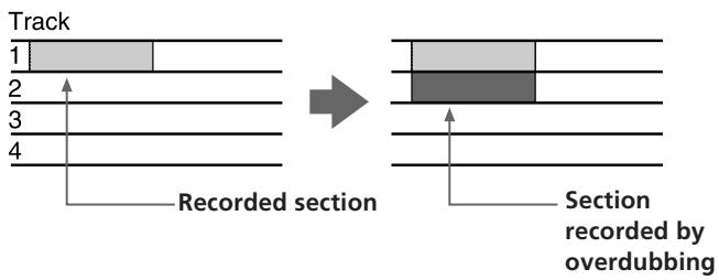
Overdub Recording
You can record other sound on a different track while listening to the playback from a previously recorded track. This kind of recording is called overdubbing.
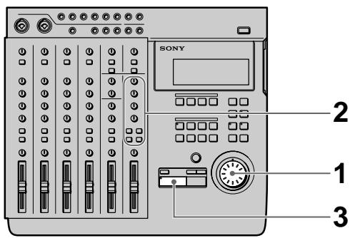
Preparations
1 Set the INPUT switch for the channel to which you will input the instrument or microphone sound to LINE/MIC (up position).
2 Set the fader for the channel to which you will input the sound to about 7 or 8.
3 Use the ASSIGN switch and PAN knobs to direct the sound to the group path you want to record.
4 Press the REC SELECT key corresponding to the group path number you selected in step 3 to specify the track to be recorded.
5 Press the monitor track set key corresponding to the group path number you selected in step 3.
6 Press CUE, then turn the TRACK knob corresponding to the track containing the recorded sound you want to hear while recording to adjust the sound to a level at which it can be monitored.
Use the MONITOR knob to adjust the monitor level.
7 Use the fader to adjust the recording level.
Play a relatively loud phrase and make adjustments by watching the level meter for the track you want to record.
If necessary, you can use the TRIM knob to adjust the recording level and equalizer.
Adjust the recording level so that the CLIP indicator does not light.
Adjust the TRIM knob so that the proper level is obtained when the fader is set between 7 and 8 to achieve good frequency characteristics.
Recording
1 Press REC.
The unit switches to record pause mode.
2 Press ▶ PLAY.
Recording begins.
Play together with the previously recorded performance.
3 When you've finished playing, press ■ STOP.
If you press ■ STOP in the middle of the song, recording stops at that counter position.
If you do not press ■ STOP in the middle of the song, recording stops automatically at the end of the song and the beginning of the song is recalled automatically.
Note
Do not turn off the power during recording. Not only may you loose the data for the current song, you may loose all of the data on the disc.
Checking the Recording
1 Turn the jog dial to set the counter to the point you want to hear.

If you set it as a locate point, it can be located immediately with the LOCATE keys.
2 Press CUE to prepare for monitoring.
Adjust the monitor volume using the respective TRACK knobs and the MONITOR knob.

Press ▶ PLAY.
Playback begins.
To rerecord
Follow the "Recording" procedure to the left.
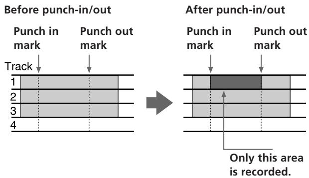
Auto Punch-In/Out Recording
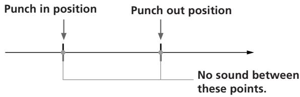
You can rerecord a certain portion of a previously recorded track. This is called punch-in/out recording. With this unit allows for 2 kinds of punch-in/out recording; auto punch-in/out, where you specify the section you desire and the unit punches in/out automatically, and manual punch-in/out, where you time the performance and punch-in/out manually at the positions you desire.
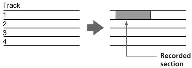
With auto punch-in/out recording, only the space between the in and out points is recordable. Therefore, you can play normally over the track but only the specified phrase will be rerecorded. The other parts of the track remain untouched.
EXAMPLE: Using punch-in/out on track 1.
Before punch-in/out
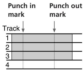

After punch-in/out
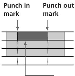
Only this area is recorded.
Setting the section to be punched in/out
Before auto punch-in/out recording you must set the record start (punch in) and record stop (punch out) positions. The punch-in/out positions must be set within the same song. Also, be sure to set the out point at a higher number than the in point.
1 Press ▶ PLAY.
Playback begins.
2 At the point you want to start recording, press MARK then press IN.
The punch in position is set at the point where you press IN.
3 At the point you want to stop recording, press MARK then press OUT.
The punch out position is set at the point where you press OUT.
4 Press ■ STOP. Playback stops
Preparations
1 Set the INPUT switch for the channel to which you will input the instrument or microphone sound to LINE/MIC (up position).
2 Set the fader for the channel to which you will input the sound to about 7 or 8.
3 Use the ASSIGN switch and PAN knobs to direct the sound to the group path you want to record.
4 Press the REC SELECT key corresponding to the group path number you selected in step 3 to specify the track to be recorded.
5 Press the monitor track set key corresponding to the group path number you selected in step 3.
6 Turn the MONITOR knob and the TRACK knob corresponding to the track containing the recorded sound you want to hear while recording to adjust the sound to a level which can be monitored.
7 Use the fader to adjust the recording level.
Play a relatively loud phrase and make adjustments by watching the level meter for the track you want to record.
If necessary, you can use the TRIM knob to adjust the recording level and equalizer.
Adjust the recording level so that the CLIP indicator does not light.
Adjust the TRIM knob so that the proper level is obtained when the fader is set between 7 and 8 to achieve good frequency characteristics.
Rehearsing the punch-in/out
You can check to make sure the record start (punch in) and record stop (punch out) positions are correct before starting punch-in/out recording. (rehearsal function)
When the rehearsal function is operative, the specified section is muted through the CUE monitor (the actual sound has not been erased). If the settings are incorrect re-specify the in and out points until the correct section has been specified. See “Correcting the position of the locate point” (page 32) for details.
The following procedure shows how to carry out the rehearsal.
1 Press AUTO PUNCH when the disc is in stop mode.
The indicator on AUTO PUNCH lights up. REC and the indicator on RHSL start blinking, and the unit enters record pause mode.
When “Undo Function On/Off” in the system settings is set to “Enabl (on)”, the indicator on the UNDO key changes accordingly.
2 Press the REC SELECT key for the track to be recorded.
3 Press ▶ PLAY.
Playback starts pre-rolling from a point slightly before the punch-in position in accordance with the "Pre-roll/Post-roll" system setting.
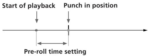
flowchart
graph TD
    A["Start of playback"] --> B["Punch in position"]
    B --> C["Pre-roll time setting"]
    C --> D["End"]
When using CUE monitor, the sound between the punch-in and punch-out positions of the track to be recorded (the track whose REC SELECT key was pressed) cannot be heard.
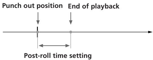
Rehearsal post-rolls to a point slightly after the punch out position in accordance with the “Pre-roll/Post-roll” system setting and then stops.
Once rehearsal has stopped, the disc automatically returns to the original point where the AUTO PUNCH key was pressed.
To stop in the middle of rehearsal Press ■ STOP.
(continued)
Recording
1 Press AUTO PUNCH when the disc is stopped. The indicator on AUTO PUNCH lights.
REC and the indicator on RHSL start blinking, and the unit enters record pause mode.
When “Undo Function On/Off” in the system settings is set to “Enabl (on)”, the indicator on the UNDO key changes accordingly.
2 Press RHSL to cancel rehearsal mode.
When “Undo Function On/Off” in the system settings is set to “Enabl (on)”, and undo is possible, the unit proceeds to back up the data.
3 Press ▶ PLAY.
Playback begins. Play together with the previously recorded performance.
When the recorder arrives at the preset punch-in position, record mode is activated automatically and the input sound is recorded on the specified track up to the punch-out point. When the recorder reaches the punch-out point, recording stops automatically, but playback continues until the post-roll point is reached.
When playback is stopped the player automatically returns to the original point.
Checking the Recording

1 Turn the jog dial to set the counter to the point you want to hear.
Pressing the IN key automatically locates the punch-in point.
2 Press CUE to prepare for monitoring. Adjust the monitor volume using the respective TRACK knobs and the MONITOR knob.
3 Press ▶ PLAY.
Playback begins.
To rerecord
Follow the "Recording" procedure to the left.
Using the UNDO function with auto punch-in/out recording
You can undo the punch-in/out immediately after execution if the system UNDO setting is set to "Enabl (on)" and the undo indicator is lit green.
To carry out the undo function, press UNDO.
Pressing undo again lets you redo the undone section (redo function).
Note
Carrying out another edit operation, starting a recording, or removing the disc after carrying out the undo or redo functions will make it impossible to undo the previous edit operation.
Notes about the color of the indicator on the UNDO key.
The color which the indicator on the UNDO key lights shows the current status. (Sometimes the indicator is off).
GREEN : undo is possible. (Redo has been carried out.)
RED : undo has been carried out
(blinking) : in the process of carrying out the undo (or redo) function.
(off): undo is not possible. (In cases where the previous operation cannot be undone (etc.).)
Manual Punch-In/Out Recording
Manual punch-in/out recording is when you start and stop recording manually with the appropriate timing instead of presetting the section to be recorded.
EXAMPLE: To punch-in/out a section on track 1.
Preparations
1 Set the INPUT switch for the channel to which you will input the instrument or microphone sound to LINE/MIC (up position).
2 Set the fader for the channel to which you will input the sound to about 7 or 8.
3 Use the ASSIGN switch and PAN knobs to direct the sound to the group path you want to record.
4 Press the monitor track set key corresponding to the group path number you selected in step 3.
5 Press CUE, then turn the TRACK knob corresponding to the track containing the recorded sound you want to hear while recording to adjust the sound to a level which can be monitored.
Use the MONITOR knob to adjust the monitor level.
6 Use the fader to adjust the recording level.
Play a relatively loud phrase and make adjustments by watching the level meter for the track you want to record.
If necessary, you can use the TRIM knob to adjust the recording level and equalizer.
Adjust the recording level so that the CLIP indicator does not light.
Adjust the TRIM knob so that the proper level is obtained when the fader is set between 7 and 8 to achieve good frequency characteristics.
Recording
(1) Using the REC key to punch-in/out.
1 Press the REC SELECT key corresponding to the group path you want to record to specify the track to be recorded.
2 Turn the jog dial to set the counter to a position before the point where you want to start recording, then press ▶ PLAY.
Playback begins.
3 When you reach the point where you want to start recording (the punch in point), press REC. The REC key lights up and recording begins.
(continued)
4 Press ▶ PLAY when you reach the point where you want to stop recording (the punch out point). The REC key goes out and the unit stops recording and switches to playback mode.
5 Press ■ STOP. Playback ends.
Setting the ASSIGN SW on the front of the unit to "REC IO" lets you use a foot switch (etc.) to activate punch-in/out recording. See "System Settings" (page 17) for details.
(2) Using the REC SELECT key to punch-in/out
1 Turn the jog dial to set the counter to a position before the point where you want to start recording, then press REC.
The REC key start blinking and the unit switches to record pause mode.
2 Press ▶ PLAY.
Playback starts, while the REC key continues blinking.
3 When you reach the point where you want to start recording (the punch in point), press the REC SELECT key for the track you want to record. The REC key lights steadily and recording begins on the specified track.
4 When you reach the point where you want to stop recording (the punch out point), press REC SELECT key for the track being recorded or press the ▶ PLAY key.
The REC key starts blinking, or goes out, and the unit stops recording and switches to playback mode.
5 Press ■ STOP.
Playback ends.
Checking the Recording
1 Turn the jog dial to set the counter to the point you want to hear.
2 Press CUE to prepare for monitoring.
Adjust the monitor volume using the respective TRACK knobs and the MONITOR knob.
3 Press ▶ PLAY.
Playback begins.
To rerecord
Follow the "Recording" procedure on the previous page.
Mix Write Recording (Basics)
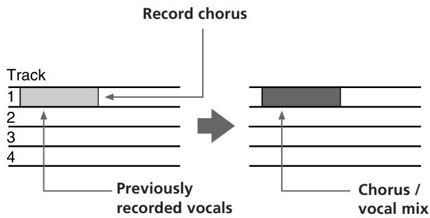
You can record other sounds on top of a previously recorded track.
The following is an explanation of the mix write concept.
EXAMPLE: Recording a chorus on top of the vocals recorded on track 1.
Since the vocals recorded on track 1 are all assigned to channel 1, connect the microphone to another channel's input jack.
During recording, the chorus vocals are mixed with the original vocals and recorded to track 1.
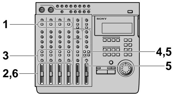
Preparations for recording
EXAMPLE: Recording a chorus on top of the vocals recorded on track 1. (For this example we will input the chorus to the INPUT CH2 jack.)
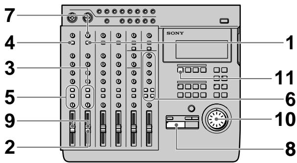
1 Set the channel 2 INPUT switch to LINE/MIC (up position).
(Set channel 2 to receive the input sound).
2 Set the fader for channel 2 to about 7 or 8.
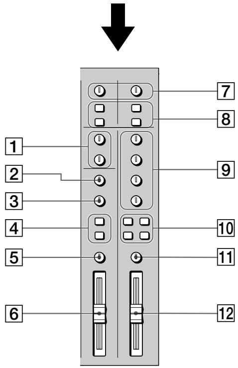
3 Set the channel 2 ASSIGN switch and PAN knobs to direct the sound to track 1.
(Set the chorus vocals input from channel 2 to be recorded on track 1.)
4 Press down the channel 1 INPUT switch.
(Input the playback sound from the recorder (TRACK 1) to channel 1.)
5 Set the channel 1 ASSIGN switch and PAN knobs to direct the playback sound from the recorder to track 1.
(Set the playback sound from the recorder to be recorded on track 1.)
6 Prepare the monitor.
- Press the monitor track key corresponding to the group path selected in steps 3 and 5 (in this case, press down the 1-2 button).
- If you want to monitor the sound of tracks 2 and 3 press the CUE key.
- Turn the MONITOR knob and the TRACK knob(s) to adjust the sound to a level that can be monitored.
7 Input a loud phrase and use the channel 2 TRIM knob to adjust the recording level.
8 Press ▶ PLAY.
Playback begins.
(continued)
9 Use the channel 1 and 2 faders to adjust the balance between the vocals and chorus to be recorded on track 1.
You may also need to adjust the monitor balance at this time.
Press the ■ STOP key after making the necessary adjustments.
10 Turn the jog dial to locate the point on the counter where the recording will begin.
11 Press the REC SELECT key for track 1. This makes it possible to record on track 1.
Recording
1 Press REC.
The unit switches to record pause mode.
2 Press ▶ PLAY.
Recording begins.
Play together with the previously recorded performance.
3 When you've finished playing, press ■ STOP.
Checking the Recording
1 Turn the jog dial to set the counter to the point you want to hear.
2 Press CUE to prepare for monitoring.
Adjust the monitor volume using the respective TRACK knobs and the MONITOR knob.
3 Press ▶ PLAY.
Playback begins.
Mix Write Recording (Applied Operations)
Mix write also comes in handy in a variety of other situations not mentioned on the previous pages. In this section we will provide 2 additional examples of mix write recording.
EXAMPLE 1: Recording the sound from tracks 1\~4 to track 4 (Ping Pong Recording)
Recording the previously recorded sound from tracks 1\~4 onto track 4.
This allows you to use tracks 1\~3 as blank tracks for recording other parts.
flowchart
graph LR
    A["1"] --> B["2"]
    B --> C["3"]
    C --> D["4"]
    style A fill:#f9f,stroke:#333
    style B fill:#f9f,stroke:#333
    style C fill:#f9f,stroke:#333
    style D fill:#f9f,stroke:#333
    subgraph Track
        direction LR
        G1[" "] --> G2[" "]
        G2 --> G3[" "]
        G3 --> G4[" "]
        G4 --> G5[" "]
    end
The previously recorded contents of tracks 1\~3 remain, but the contents of tracks 1\~4 have been recorded together on track 4.
Preparations
1 Press down the INPUT switches on channels 1\~4. (Set channels 1\~4 to receive the (TRACK) sound played back from the recorder.)
2 Set the faders for channels 1\~4 to about 7 or 8.
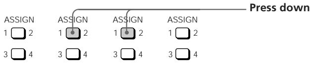
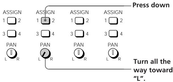
3 Set the ASSIGN switches and PAN knobs for channels 1\~4 to direct the sound to track 4. (Set the playback sounds input from the recorder to channels 1\~4 to be recorded on track 4.)
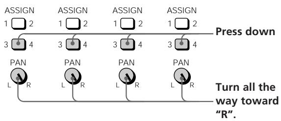
flowchart
graph TD
    A["ASSIGN 1 2"] --> B["Press down"]
    C["ASSIGN 3 4"] --> B
    D["ASSIGN 1 2"] --> B
    E["ASSIGN 3 4"] --> B
    F["ASSIGN 1 2"] --> B
    G["ASSIGN 3 4"] --> B
    H["PAN L R"] --> I["Turn all the way toward "R"."]
    J["PAN L R"] --> I
    K["PAN L R"] --> I
    L["PAN L R"] --> I
4 Prepare the monitor.
- Press the monitor track key corresponding to the group path selected in step 3 (in this case, press 3-4).
- Turn the MONITOR knob and the TRACK knob(s) to adjust the sound to a level that can be monitored.
5 Press ▶ PLAY. Playback begins.
6 Use the faders for channels 1\~4 to adjust the record balance of the sound to be recorded on track 4.
You may also need to adjust the monitor balance at this time.
Press the ■ STOP key after making the necessary adjustments.
7 Turn the jog dial to locate the point on the counter where the recording will begin.
8 Press the REC SELECT key for track 4. This makes it possible to record on track 4.
Recording
1 Press REC. The unit switches to record pause mode.
2 Press ▶ PLAY. Recording begins. Play together with the previously recorded performance.
3 When you've finished playing, press ■ STOP.
Checking the Recording
1 Turn the jog dial to set the counter to the point you want to hear.
2 Press CUE to prepare for monitoring.
Adjust the monitor volume using the respective TRACK knobs and the MONITOR knob.
3 Press ▶ PLAY.
Playback begins.
Make sure the CLIP indicator on the level meter does not light.
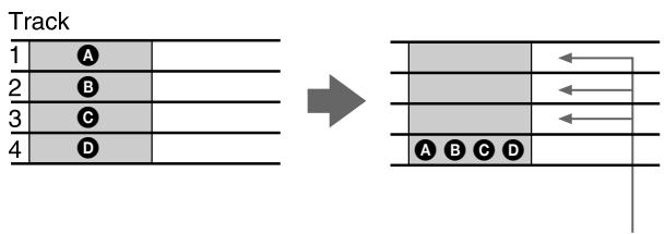
EXAMPLE 2: Recording the sound from tracks 1\~4 to tracks 1 and 2 (Bounce Recording)
Recording the previously recorded sound from tracks 1\~4 in a stereo mix to tracks 1 and 2.
This allows you to use tracks 3 and 4 as blank tracks for recording other parts.
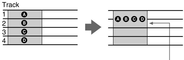
flowchart
graph LR
    A["Track 1"] --> B["Track 2"]
    B --> C["Track 3"]
    C --> D["Track 4"]
    D --> E["→"]
    E --> F["Block A B C D"]
    F --> G["Arrow pointing inward"]
The previously recorded contents of tracks 3 and 4 remain, but the contents of tracks 1\~4 have been recorded together in a stereo mix on tracks 1 and 2.
(continued)
Preparations
1 Press down the INPUT switches on channels 1\~4. (Set channels 1\~4 to receive the (TRACK) sound played back from the recorder.)
2 Set the faders for channels 1\~4 to about 7 or 8.
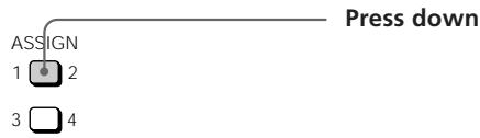
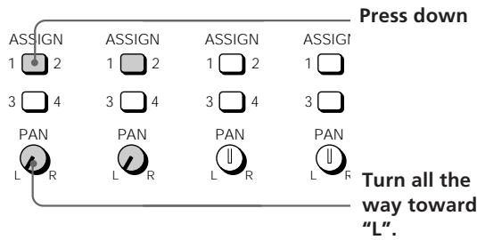
3 Set the ASSIGN switches and PAN knobs for channels 1\~4 to direct the sound to tracks 1 and 2. (Set the playback sounds input from the recorder to channels 1\~4 to be recorded on tracks 1 and 2.)
4 Prepare the monitor.
- Press the monitor track key corresponding to the group path selected in step 3 (In this case, press 1-2).
- Turn the MONITOR knob and the TRACK knob(s) to adjust the sound to a level that can be monitored.
5 Press ▶ PLAY.
Playback begins.
6 Use the faders for channels 1\~4 to adjust the record balance of the sound to be recorded on tracks 1 and 2.
You may also need to adjust the monitor balance at this time.
Press the ■ STOP key after making the necessary adjustments.
7 Turn the jog dial to locate the point on the counter where the recording will begin.
8 Press the REC SELECT key for tracks 1 and 2. This makes it possible to record on tracks 1 and 2.
Recording
1 Press REC.
The unit switches to record pause mode.
2 Press ▶ PLAY.
Recording begins.
Play together with the previously recorded performance.
3 When you've finished playing, press ■ STOP.
Checking the Recording
1 Turn the jog dial to set the counter to the point you want to hear.
2 Press CUE to prepare for monitoring.
Adjust the monitor volume using the respective TRACK knobs and the MONITOR knob.
3 Press ▶ PLAY.
Playback begins.
Track Edit Overview
The track editing operations let you specify a part (an arbitrary section of an arbitrary track) and copy it over another part, move it to another position, or remove the sound from it. You can also switch the positions of two parts.
Additionally, you can edit between different songs as well as within the same song.
The track editing functions consist of the following:
- Track Copy (duplicating a part) page 33
- Track Move (moving a part) page 34
- Track Exchange (switching the positions of 2 parts) page 35
- Track Erase (erasing a part) page 36
Using the Undo Function with track editing operations
You can undo an edit immediately after execution if the undo indicator is lit green.
To carry out the undo function, press UNDO.
Pressing undo again lets you redo the undone edit operation (redo function).
Note
Carrying out another edit operation, starting a recording, or removing the disc after carrying out the undo or redo functions will make it impossible to undo the previous edit operation.
Notes about the color of the indicator on the UNDO key.
The color which the indicator on the UNDO key lights shows the current status. (Sometimes the indicator is off).
GREEN : undo is possible. (Redo has been carried out.)
RED : undo has been carried out
(blinking): in the process of carrying out the undo (or redo) function.
(off): undo is not possible. (In cases where the previous operation cannot be undone (etc.).)
Specifying the Locate Points
Before editing, it is necessary to specify the locate points (edit points). There are the following eleven types of locate points:
• IN (edit start) point
Represents the beginning of the part to be edited.
- OUT (edit end) point
Represents the end of the part to be edited.
- DEST (edit destination) point
Represents the place where the part will be copied to during the copy operation (etc.).
- A\~H points
Additional arbitrary locate points (not used for editing operations).
Setting edit points by specifying the time/bar
Use the following procedure when you know the time/bar of the locate points for the desired part.
1 Turn the jog dial during stop mode to display the time/bar you desire.
Holding down the SHIFT key and pressing the DISPLAY key lets you switch the display between time and bars.
To select the desired song, use the ◀◀◀ and ▶▶◀ keys.
(continued)
2 Press MARK.
The indicator on the MARK key starts blinking.
3 Press the key for the locate point you desire.
- IN point : Press IN.
• OUT point : Press OUT. - DEST (destination) point : Hold down the SHIFT key and press IN.
- A\~D (E\~H) points: Press A\~D (Hold down the SHIFT key and press A\~D).
The time/bar in the display is set as the respective locate point.
Setting edit points while listening to the sound being played back
Use the following procedure to set locate points while listening to the sound being played back.
1 Press ▶ PLAY.
Playback begins.
2 Press MARK before setting the locate point. The indicator on the MARK key starts blinking.
3 Press the key for the locate point you desire.
- IN point : Press IN.
- OUT point : Press OUT.
- DEST (destination) point : Hold down the SHIFT key and press IN.
- A\~D (E\~H) points: Press A\~D (Hold down the SHIFT key and press A\~D).
The locate point is set at the place where you press the IN, OUT, DEST or A\~D (E\~H) key.
Correcting the position of the locate point
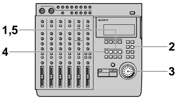
1 Press the key for the point you wish to correct.
- IN point : Press IN.
- OUT point : Press OUT.
- DEST (destination) point : Hold down the SHIFT key and press IN.
- A\~D (E\~H) points : Press A\~D (Hold down the SHIFT key and press A\~D).
The time/bar for the respective locate point appears in the display.
2 Press RHSL.
The indicator on the RHSL key starts to blink and playback repeats around the locate point.
- When the rehearsal mode (page 18) setting is ↑: the volume increases when the locate point is passed.
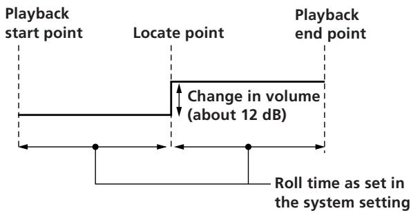
- When the rehearsal mode (page 18) setting is ↓: the volume decreases when the locate point is passed.
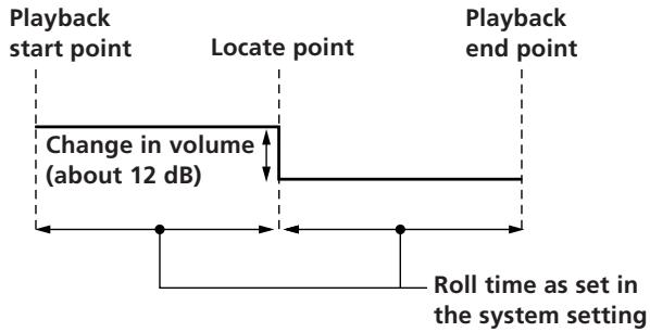
flowchart
graph LR
    A["Playback start point"] --> B["Locate point"]
    B --> C["Playback end point"]
    D["Change in volume (about 12 dB)"] --> B
    E["Roll time as set in the system setting"] --> C

During rehearsal mode, press the ◀◀ or ▶▶◆ key to switch between increased or decreased volume after the locate point.
3 Turn the jog dial to adjust the position of the locate point.
The locate point moves in proportion to the rotation of the jog dial each time the section is repeated.
4 Press MARK.
The indicator on the MARK key starts blinking.
5 Press the key for the locate point you desire.
Playback stops and the locate point is set to the new position.
To stop before completing the correction
Press ■ STOP to stop playback.
Notes
- Be sure to set the out point at a higher number than the in point.
- Be sure to set the punch-in/out positions within the same song.
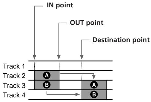
Copying a Part (Track Copy)
You can copy part of a track and place it in another location. If the location points are in the same position, you can copy parts from more than one track at the same time.
flowchart
graph TD
    A["IN point"] --> B["OUT point"]
    B --> C["Destination point"]
    D["Track 1"] --> E["A"]
    F["Track 2"] --> G["B"]
    H["Track 3"] --> I["A"]
    J["Track 4"] --> K["B"]
    style A fill:#f9f,stroke:#333
    style B fill:#ccf,stroke:#333
    style C fill:#cfc,stroke:#333
    style D fill:#fcc,stroke:#333
    style E fill:#ffc,stroke:#333
    style F fill:#fcc,stroke:#333
    style G fill:#ffc,stroke:#333
    style H fill:#fcc,stroke:#333
    style I fill:#ffc,stroke:#333
    style J fill:#fcc,stroke:#333
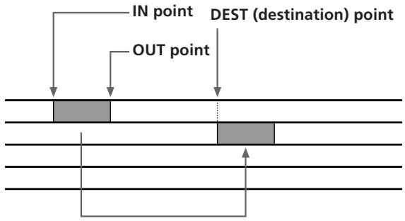
The original sound recorded after the destination point is erased and rewritten by the part between the in and out points.
Preparations
Set the following locate points before carrying out the edit operation.
• IN point : the beginning of the part to be copied.
- OUT point: the end of the part to be copied.
- DEST (destination) point : the beginning of the part to be rewritten.
See "Specifying the Location Points" (page 31) for details on how to set the location points.
Editing Operation

1 Press EDIT.
EDIT appears in the display.
(continued)
2 Turn the jog dial so that "Trak Copy" appears in the display.
The name of the edit function starts blinking in the display.
3 Press ENTER.
The edit setting items appear in the display.
4 Turn the jog dial to display the setting you desire. This determines which tracks the part will be copied from and which tracks the part will be copied to.
Use the jog dial to specify the copy destination track numbers in the space underneath the track indicator(s) ( 1 mark) for the part to be copied.
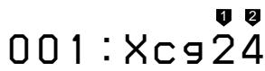
Example display:
001:Cpy 34
To set other tracks press ENTER and proceed to the next step.
Press EXIT to return to the original settings.
If you do not want to specify any tracks, leave the destination track number display empty.
5 Press ENTER.
Once all the track settings have been displayed, "OK?" appears in the display.
6 Press ENTER again.
The selected part is copied.
If you do not wish to carry out the edit operation, press EXIT.
When the edit operation has finished, the edit select screen reappears.
7 Press EXIT.
This completes the edit operation.
Note
It is not possible to set the destination point between the in and out points when copying to the same track.
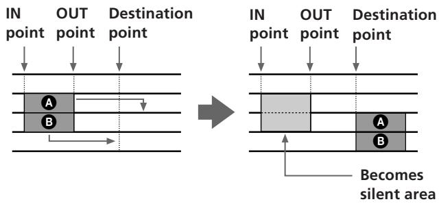
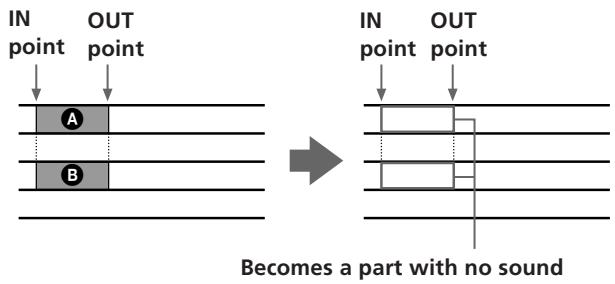
Moving a Part (Track Move)
You can move part of a track to a different position in a different track.
flowchart
graph TD
    A["Rectangular Block A"] --> B["Rectangular Block B"]
    style A fill:#f9f,stroke:#333
    style B fill:#f9f,stroke:#333
    note right of A: 'Becomes silent area'
    note right of B: 'IN point', 'OUT point', 'Destination point'
The space between the original in and out points becomes a silent area.
Preparations
Set the following locate points before carrying out the edit operation.
• IN point : the beginning of the part to be copied.
- OUT point: the end of the part to be copied.
- DEST (destination) point : the beginning of the part to be rewritten.
See “Specifying the Locate Points” (page 31) for details on how to set the location points.
Editing Operation

1 Press EDIT.
EDIT appears in the display.
2 Turn the jog dial so that "Trak Move" appears in the display.
The name of the edit function starts blinking in the display.
3 Press ENTER.
The edit setting items appear in the display.
4 Turn the jog dial to display the setting you desire. This determines which tracks the part will be moved to.
Use the jog dial to display the move destination track numbers in the space below the move origin track number indicator(s) ( 1 mark).
Example display:

To set other tracks press ENTER and proceed to the next step.
Press EXIT to return to the original settings.
If you do not want to specify any tracks, leave the destination track number display empty.
5 Press ENTER.
Once all the track settings have been displayed, "OK?" appears in the display.
6 Press ENTER again.
The selected part is copied.
If you do not wish to carry out the edit operation, press EXIT.
When the edit operation has finished, the edit select screen reappears.
7 Press EXIT.
This completes the edit operation.
Note
It is not possible to set the destination point between the in and out points when moving within the same track.
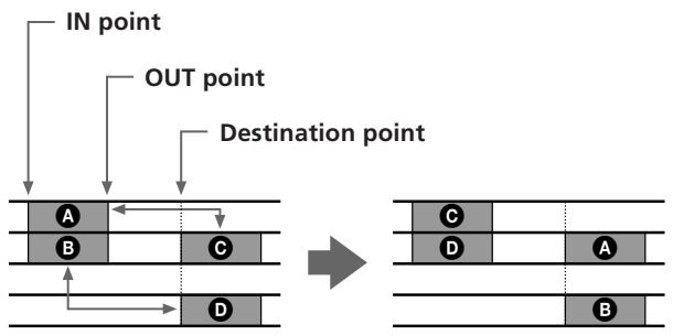
Switching the Locations of 2 Parts (Track Exchange)
You can switch the location one part of a track with another part of any other track.
flowchart
graph TD
    A["Destination point"] --> B["IN point"]
    A --> C["OUT point"]
    B --> D["A"]
    C --> E["B"]
    D <--> F["C"]
    E <--> G["D"]
    H["→"] --> I["Final state block"]
    style A fill:#f9f,stroke:#333
    style B fill:#ccf,stroke:#333
    style C fill:#cfc,stroke:#333
    style D fill:#fcc,stroke:#333
    style E fill:#cff,stroke:#333
    style F fill:#ffc,stroke:#333
    style G fill:#fcc,stroke:#333
    style H fill:#ffc,stroke:#333
Preparations
Set the following locate points before carrying out the edit operation.
- IN point : the beginning of the part to be copied.
- OUT point: the end of the part to be copied.
- DEST (destination) point : the beginning of the part to be rewritten.
See “Specifying the Locate Points” (page 31) for details on how to set the location points.
Editing Operation
1 Press EDIT.
EDIT appears in the display.
2 Turn the jog dial so that "Trak Xchnge" appears in the display.
The name of the edit function starts blinking in the display.
(continued)
3 Press ENTER.
The edit setting items appear in the display.
4 Turn the jog dial to display the setting you desire. This determines which tracks the parts will be exchanged to.
Use the jog dial to display the exchange destination track number(s) below the exchange origin track number indicator(s) ( 1 mark).
Example display:
To set other tracks press ENTER and proceed to the next step.
Press EXIT to return to the original settings.
If you do not want to specify any tracks, leave the destination track number display empty.
5 Press ENTER.
Once all the track settings have been displayed, "OK?" appears in the display.
6 Press ENTER again.
The selected part is copied.
If you do not wish to carry out the edit operation, press EXIT.
When the edit operation has finished, the edit select screen reappears.
7 Press EXIT.
This completes the edit operation.
Note
It is not possible to set the edit points to exchange overlapping parts.
Erasing a Part (Track Erase)
You can erase part of a track. The part which was erased becomes a part with no sound.
Preparations
Set the following locate points before carrying out the edit operation.
• IN point : the beginning of the part to be copied.
- OUT point: the end of the part to be copied.
See “Specifying the Locate Points” (page 31) for details on how to set the location points.
Editing Operation
1 Press EDIT.
EDIT appears in the display.
2 Turn the jog dial so that "Trak Erase" appears in the display.
The name of the edit function starts blinking in the display.
3 Press ENTER.
The edit setting items appear in the display.
4 Turn the jog dial to display the setting you desire.
This determines which tracks the part will be erased from.
Use the jog dial to display the track number(s) containing the part(s) to be erased below the respective track number indicator(s) ( 1 mark).
Example display:

To set other tracks press ENTER and proceed to the next step.
Press EXIT to return to the original settings.
If you do not want to specify a track, leave an empty space below the respective track number indicator.
5 Press ENTER.
"OK?" appears in the display.
6 Press ENTER again.
The selected part is copied.
If you do not wish to carry out the edit operation, press EXIT.
When the edit operation has finished, the edit select screen reappears.
7 Press EXIT.
This completes the edit operation.
Section Edit Overview
The section editing operations let you specify sections common to all 4 tracks and move them to other positions in the song, duplicate them, or remove them. You can also switch the positions of two sections.
The section editing functions consist of the following:
• Section Move (moving a section) → page 39
• Section Exchange (switching 2 sections) → page 40
- Section Insert (duplicating and inserting a section) → page 41
• Section Delete (for deleting a section) → page 42
Notes
- It is not possible to perform recording operations, such as punch-in/out recording on a song that has been modified with section editing.
In order to perform punch-in/out recording operations after a song has been edited, you must copy the entire song, then record or edit the copied version of the song. ":" blinks next to the song number of songs which have been modified with the section edit function.
See "Copying a Song (Song Copy)" on page 43 for details on how to copy a song. - Short sections* cannot be edited. This is due to the nature of the MD system, and is not a malfunction.
* With 4 tracks = less than approximately 4 seconds. With 2 tracks = less than approximately 8 seconds. With 1 track = less than approximately 16 seconds. - Section editing is only complete once the TOC data has been updated. You can update the TOC data by pressing STOP during stop mode. The TOC data is also updated automatically when the disc is ejected. Therefore, always eject the disc before turning off the power. Not only is there a danger of loosing the song being edited, there is also a possibility of loosing the contents of the entire disc.
Using the Undo Function with section editing operations
You can undo an edit immediately after execution if the undo indicator is lit green.
To carry out the undo function, press UNDO.
Pressing undo again lets you redo the undone edit operation (redo function).
Note
Carrying out another edit operation, starting a recording, or removing the disc after carrying out the undo or redo functions will make it impossible to undo the previous edit operation.
Notes about the color of the indicator on the UNDO key.
The color which the indicator on the UNDO key lights shows the current status. (Sometimes the indicator is off).
GREEN : undo is possible. (Redo has been carried out.)
RED : undo has been carried out
(blinking): in the process of carrying out the undo (or redo) function.
(off): undo is not possible. (In cases where the previous operation cannot be undone (etc.).)
Specifying the Locate Points
Before editing, it is necessary to specify the locate points (edit points). There are the following three types of locate points:
• IN (edit start) point :
Represents the beginning of the section to be edited.
- OUT (edit end) point :
Represents the end of the section to be edited.
- DEST (edit destination) point :
Represents the edit destination for move, exchange, and insert operations.
See "Specifying the Locate Points" on page 31 for details on how to set the location points.
Notes
- Be sure to set the out point at a higher number than the in point.
- Be sure to set the punch-in/out positions within the same song.
Moving a Section (Section Move)
You can move a section to a different place in the song. The section to be moved is inserted at the point specified by the destination point.
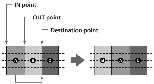
flowchart
graph TD
    A["Destination point"] --> B["IN point"]
    A --> C["OUT point"]
    B --> D["A"]
    C --> E["B"]
    D --> F["C"]
    E --> G["B"]
    F --> H["A"]
    G --> I["C"]
The selected section is moved.
A disappears and is moved to the destination point.
Preparations
Set the following locate points before carrying out the edit operation.
• IN point : the beginning of the part to be copied.
- OUT point: the end of the part to be copied.
- DEST (destination) point : the beginning of the part to be rewritten.
See "Specifying the Location Points" (page 31) for details on how to set the location points.
Editing Operation
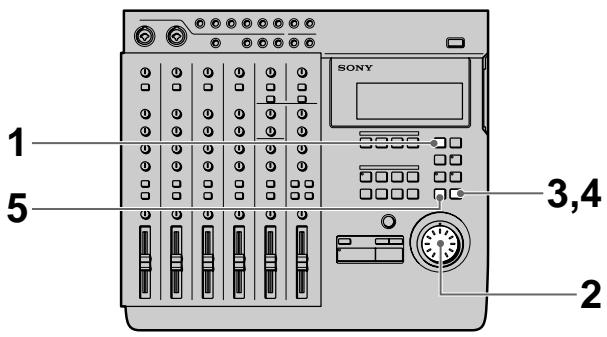
1 Press EDIT.
EDIT appears in the display.
2 Turn the jog dial so that "Sect Move" appears in the display.
The name of the edit function starts blinking in the display.
3 Press ENTER.
"OK?" appears in the display.
001: Mov, OK?
4 Press ENTER again.
The selected edit operation is carried out.
To start over again from the beginning, or quit the edit operation, press EXIT instead of ENTER.
When the edit operation has finished, the edit select screen reappears.
To carry out another edit operation in succession use the jog dial to specify the operation you desire.
5 Press EXIT.
This completes the edit operation.
Switching the Locations of 2 Sections (Section Exchange)
You can switch the location of two sections.
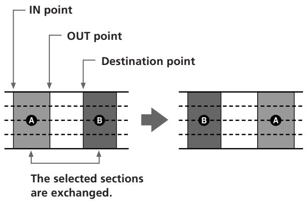
flowchart
graph TD
    A["IN point"] --> B["Section A"]
    C["OUT point"] --> D["Section B"]
    E["Destination point"] --> F["Section B"]
    G["The selected sections are exchanged."] --> H["Section A"]
Preparations
Set the following locate points before carrying out the edit operation.
- IN point: the beginning of the part to be copied.
- OUT point: the end of the part to be copied.
- DEST (destination) point : the beginning of the part to be rewritten.
See “Specifying the Locate Points” (page 31) for details on how to set the location points.
Editing Operation

1 Press EDIT.
EDIT appears in the display.
2 Turn the jog dial so that "Sect Xchnge" appears in the display.
The name of the edit function starts blinking in the display.
3 Press ENTER.
"OK?" appears in the display.
001:Xcg,OK?
4 Press ENTER again.
The selected edit operation is carried out.
To start over again from the beginning, or quit the edit operation, press EXIT instead of ENTER.
When the edit operation has finished, the edit select screen reappears.
To carry out another edit operation in succession use the jog dial to specify the operation you desire.
5 Press EXIT.
This completes the edit operation.
Note
It is not possible to set the destination point between the in and out points.
Inserting Another Section (Section Insert)
This function lets you copy a section and insert it at another place in the song.
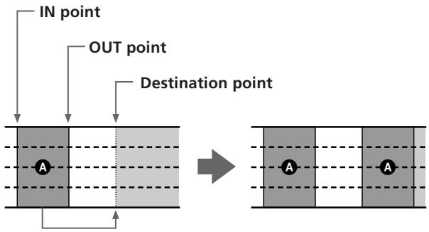
flowchart
graph TD
    A["Destination point"] --> B["IN point"]
    A --> C["OUT point"]
    B --> D["Block with A"]
    C --> E["Block with A"]
    D --> F["Final Block with A"]
    E --> F
The original section is copied and inserted at the destination point.
Preparations
Set the following locate points before carrying out the edit operation.
• IN point : the beginning of the part to be copied.
- OUT point: the end of the part to be copied.
- DEST (destination) point : the beginning of the part to be rewritten.
See “Specifying the Locate Points” (page 31) for details on how to set the location points.
Editing Operation
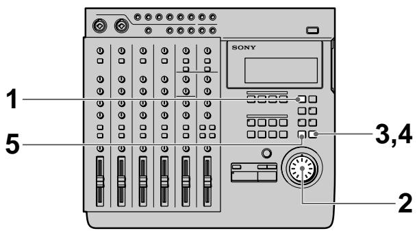
1 Press EDIT.
EDIT appears in the display.
2 Turn the jog dial so that "Sect Insert" appears in the display.
The name of the edit function starts blinking in the display.
3 Press ENTER.
"OK?" appears in the display.
001:Ins,OK?
4 Press ENTER again.
The selected edit operation is carried out.
To start over again from the beginning, or quit the edit operation, press EXIT instead of ENTER.
When the edit operation has finished, the edit select screen reappears.
To carry out another edit operation in succession use the jog dial to specify the operation you desire.
5 Press EXIT.
This completes the edit operation.
Deleting a Section (Section Delete)
This function lets you delete a section of the song.
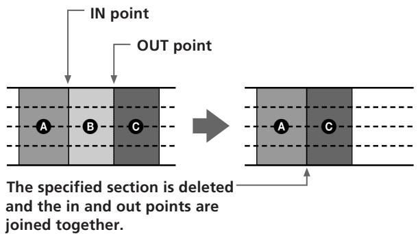
flowchart
graph TD
    A["IN point"] --> B["OUT point"]
    B --> C["Section A: deleted"]
    B --> D["Section B: deleted"]
    B --> E["Section C: deleted"]
    C --> F["The specified section is deleted and the in and out points are joined together."]
    D --> F
    E --> F
Preparations
Set the following locate points before carrying out the edit operation.
- IN point: the beginning of the part to be copied.
- OUT point: the end of the part to be copied.
See "Specifying the Locate Points" (page 31) for details on how to set the location points.
Editing Operation

1 Press EDIT.
EDIT appears in the display.
2 Turn the jog dial so that "Sect Delete" appears in the display.
The name of the edit function starts blinking in the display.
3 Press ENTER.
"OK?" appears in the display.
001:Del,OK?
4 Press ENTER again.
The selected edit operation is carried out.
To start over again from the beginning, or quit the edit operation, press EXIT instead of ENTER.
When the edit operation has finished, the edit select screen reappears.
To carry out another edit operation in succession use the jog dial to specify the operation you desire.
5 Press EXIT.
This completes the edit operation.
Song Edit Overview
The following sections show you how to divide a completed song and connect 2 adjacent songs (etc.) so you can easily locate the positions you desire on the recorded disc.
The following is a list of song editing functions :
- Song Copy (copying a song) page 43
- Song Move (moving a song) page 44
- Song Exchange (switching the positions of 2 songs) page 45
- Song Divide (dividing 1 song into 2 different songs) page 46
- Song Combine (combining 2 songs) page 47
- Song Delete (deleting a song) page 48
- Song Name (naming a song) page 49
- Song Tempo (creating a tempo map) page 53
Note
Song editing is only complete once the TOC data has been updated. You can update the TOC data by pressing STOP during stop mode. The TOC data is also updated automatically when the disc is ejected. Therefore, always eject the disc before turning off the power. Not only is there a danger of loosing the song being edited, there is also a possibility of loosing the contents of the entire disc.
Using the Undo Function with section editing operations
You can undo an edit immediately after execution if the undo indicator is lit green.
To carry out the undo function, press UNDO.
Pressing undo again lets you redo the undone edit operation (redo function).
Note
Carrying out another edit operation, starting a recording, or removing the disc after carrying out the undo or redo functions will make it impossible to undo the previous edit operation.
Notes about the color of the indicator on the UNDO key.
The color which the indicator on the UNDO key lights shows the current status. (Sometimes the indicator is off).
GREEN : Undo is possible. (Or Redo has been carried out.)
RED : Undo has been carried out
(blinking) : In the process of carrying out the undo (or redo) function.
(off): Undo is not possible. (In cases where the previous operation cannot be undone (etc.).)
Copying a Song (Song Copy)
This function lets you duplicate a song. Newly created copy is treated as a new recording and becomes the last song on the disc. This is a convenient way to backup songs before editing.
Copying the second song.
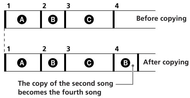
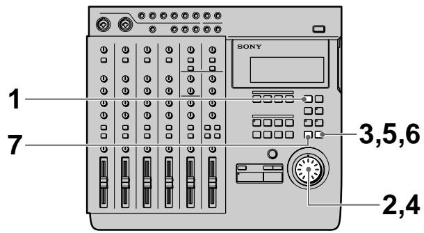
1 Press EDIT.
EDIT appears in the display.
2 Turn the jog dial so that "Song Copy" appears in the display.
The name of the edit function starts blinking in the display.
3 Press ENTER.
The edit setting items appear in the display.
4 Turn the jog dial to display the number song you want to copy.
Cpy 002
5 Press ENTER
"OK?" appears in the display.
(continued)
6 Press ENTER again.
The selected song is copied.
To start over again from the beginning, or quit the edit operation, press EXIT instead of ENTER. When the edit operation has finished, the edit select screen reappears.
To carry out another edit operation in succession use the jog dial to specify the operation you desire.
7 Press EXIT.
This completes the edit operation.
Moving a Song (Song Move)
This function lets you change the order of the songs by moving the song you select to a different position.
Moving the second song to the third song.
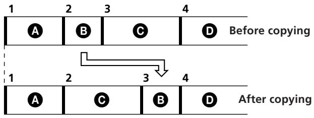
flowchart
graph TD
    A["1"] --> B["2"]
    B --> C["3"]
    C --> D["4"]
    E["Before copying"] --> F["1"]
    F --> G["2"]
    G --> H["3"]
    H --> I["4"]
    J["After copying"] --> K["1"]
    K --> L["2"]
    L --> M["3"]
    M --> N["4"]
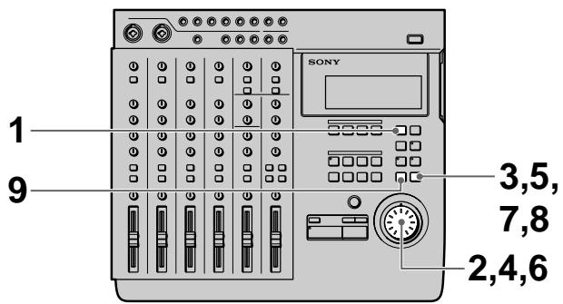
1 Press EDIT.
EDIT appears in the display.
2 Turn the jog dial so that "Song Move" appears in the display.
The name of the edit function starts blinking in the display.
3 Press ENTER.
The edit setting items appear in the display.
Mov 002>003
4 Turn the jog dial to display the song number you want to move.
5 Press ENTER.
6 Turn the jog dial to display the number you want to move the selected song to.
7 Press ENTER
"OK?" appears in the display.
8 Press ENTER again.
The selected song is moved.
To start over again from the beginning, or quit the edit operation, press EXIT instead of ENTER.
When the edit operation has finished, the edit select screen reappears.
To carry out another edit operation in succession use the jog dial to specify the operation you desire.
9 Press EXIT.
This completes the edit operation.
Changing the Song Order (Song Exchange)
This function lets you switch the position of 2 songs of your choice. New consecutive song numbers are assigned automatically.
Switching songs 2 and 4.
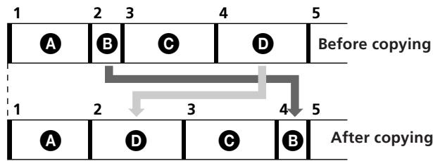
flowchart
graph TD
    A["1"] --> B["2"]
    B --> C["3"]
    C --> D["4"]
    D --> E["5"]
    F["Before copying"] --> G["1"]
    G --> H["2"]
    H --> I["3"]
    I --> J["4"]
    J --> K["5"]
    L["After copying"] --> M["1"]
    M --> N["2"]
    N --> O["3"]
    O --> P["4"]
    P --> Q["5"]
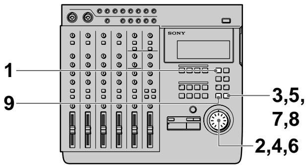
1 Press EDIT.
EDIT appears in the display.
2 Turn the jog dial so that "Song Xchnge" appears in the display.
The name of the edit function starts blinking in the display.
3 Press ENTER.
The edit setting items appear in the display.
Xcg 002-004
4 Turn the jog dial to display the first song number you want to exchange.
5 Press ENTER.
(continued)
6 Turn the jog dial to display the song number you want to exchange the first song with.
7 Press ENTER
"OK?" appears in the display.
8 Press ENTER again.
The selected songs are exchanged.
To start over again from the beginning, or quit the edit operation, press EXIT instead of ENTER.
When the edit operation has finished, the edit select screen reappears.
To carry out another edit operation in succession use the jog dial to specify the operation you desire.
9 Press EXIT.
This completes the edit operation.
Dividing a Song (Song Divide)
This function lets you divide a song into different songs. New consecutive song numbers are assigned automatically.
Dividing the second song into sections (B) and (C).
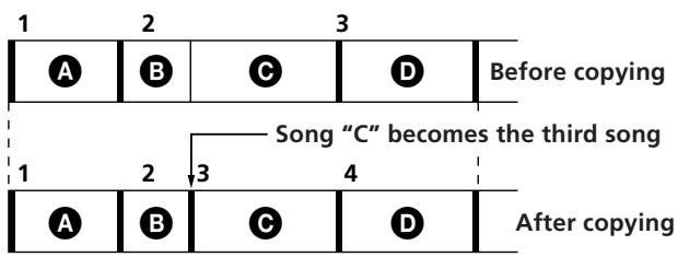
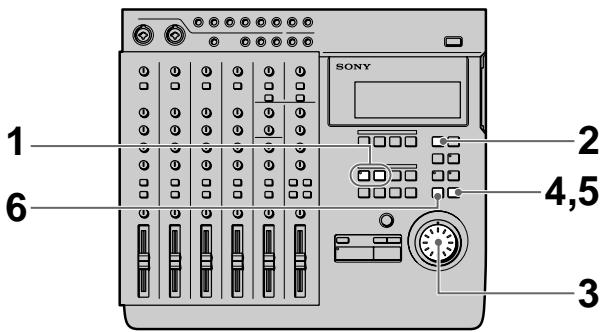
1 Set a locate point (in point) at the position where you want to divide the song.
2 Press EDIT.
EDIT appears in the display.
3 Turn the jog dial so that "Song Divide" appears in the display.
The name of the edit function starts blinking in the display.
4 Press ENTER.
"OK?" appears in the display.
002:Div,OK?
5 Press ENTER again.
The song is divided at the specified point.
To start over again from the beginning, or quit the edit operation, press EXIT instead of ENTER.
When the edit operation has finished, the edit select screen reappears.
To carry out another edit operation in succession use the jog dial to specify the operation you desire.
6 Press EXIT.
This completes the edit operation.
Connecting 2 Songs (Song Combine)
This function lets you combine two songs into one.
You can use this function to connect songs for continuous playback, or combine a series of separate recordings into a single song (etc.).
Note
It is not possible to perform recording operations, such as punch-in/out recording on songs created from combinations of other songs using the song combine edit function.
In order to perform punch-in/out recording operations after a song combine, you must copy the entire song (Song Copy), then record or edit the copied version of the song.
“:” blinks next to the song number of songs created using the song combine edit function.
If “:” is blinking next to one of the two song numbers to be combined, that song cannot be combined due to the limitations of the MD recording system. In such a case, copy the song (Song Copy) with the blinking “:” before performing the song combine edit function.
See “Copying a Song (Song Copy)” on page 43 for details on how to copy a song.
Creating one song by combining songs 2 and 3.
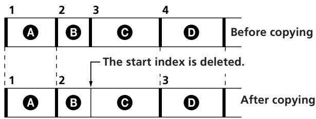
flowchart
graph TD
    A["1"] --> B["2"]
    B --> C["3"]
    C --> D["4"]
    D --> E["Before copying"]
    F["1"] --> G["2"]
    G --> H["3"]
    H --> I["After copying"]
    style A fill:#fff,stroke:#000
    style B fill:#fff,stroke:#000
    style C fill:#fff,stroke:#000
    style D fill:#fff,stroke:#000
    style E fill:#fff,stroke:#000
    style F fill:#fff,stroke:#000
    style G fill:#fff,stroke:#000
    style H fill:#fff,stroke:#000
    style I fill:#fff,stroke:#000
    note right of G The start index is deleted.

1 Press EDIT.
EDIT appears in the display.
2 Turn the jog dial so that "Song Combin" appears in the display.
The name of the edit function starts blinking in the display.
(continued)
3 Press ENTER.
The edit setting items appear in the display.
Cmb 002+003
4 Turn the jog dial to display the song number you want to combine as the first half of the new song.
5 Press ENTER.
6 Turn the jog dial to display the song number you want to combine as the second half of the new song.
7 Press ENTER
"OK?" appears in the display.
8 Press ENTER again.
The selected songs are combined.
To start over again from the beginning, or quit the edit operation, press EXIT instead of ENTER.
When the edit operation has finished, the edit select screen reappears.
To carry out another edit operation in succession use the jog dial to specify the operation you desire.
9 Press EXIT.
This completes the edit operation.
Deleting a Song (Song Delete)
This function allows you to easily delete a recorded song by specifying its song number. To delete all of the songs on the disc, see “Erasing the Disc Contents (Disc Erase)” on page 50.
New consecutive song numbers are automatically assigned to the songs following the deleted song. For example, if you delete song number 1, song number 2 becomes the song number 1.
This feature is convenient because there is no need to record “over” old material, as with cassette tapes.
Deleting the second song.
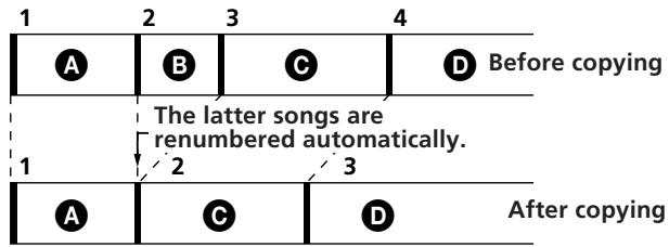
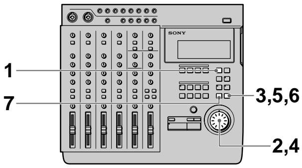
1 Press EDIT.
EDIT appears in the display.
2 Turn the jog dial so that "Song Delete" appears in the display.
The name of the edit function starts blinking in the display.
3 Press ENTER.
The edit setting items appear in the display.
Del 002
4 Turn the jog dial to display the song number you want to delete.
5 Press ENTER
"OK?" appears in the display.
6 Press ENTER again.
The selected songs are exchanged.
To start over again from the beginning, or quit the edit operation, press EXIT instead of ENTER.
When the edit operation has finished, the edit select screen reappears.
To carry out another edit operation in succession use the jog dial to specify the operation you desire.
7 Press EXIT.
This completes the edit operation.
Naming a Song (Song Name)
This function lets you assign names to songs using upper and lower case letters of the alphabet, numbers, and symbols.
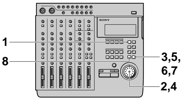
1 Press EDIT.
EDIT appears in the display.
2 Turn the jog dial so that "Song Name" appears in the display.
The name of the edit function starts blinking in the display.
3 Press ENTER.
The edit setting items appear in the display.
4 Turn the jog dial to display the character you desire.
The selected character blinks. In addition to the letters of the alphabet, you can also use numbers and symbols. The symbols which can be displayed are as follows:
$$ \begin{array}{l} \text {!}" # \% \& ^ {\prime} (\text {) } * +, -. /:; < = >? @ \ \wedge_ {-} \text {` (blank)} \end{array} $$
5 Press ENTER.
The character selected in step 4 lights steadily and the cursor starts blinking in the next position.
To go back to the previous position, press EXIT.
6 Repeat steps 4 and 5 until to complete the title.
7 Press EXIT when the cursor is in the leftmost position or
press ENTER when the cursor is in the rightmost position to enter the final name.
To carry out another edit operation in succession use the jog dial to specify the operation you desire.
8 Press EXIT.
This completes the edit operation.
Overview
This chapter shows you how to erase all the information on the disc and how to assign a disc name.
The following is a list of disc editing functions :
• Disc Erase (for erasing a disc) → page 50
• Disc Name (for naming a disc) → page 51
Erasing the Disc Contents (Disc Erase)
This function erases the entire disc. Both the recorded audio data and the disc name will be erased.

1 Press EDIT.
EDIT appears in the display.
2 Turn the jog dial so that "Disc Erase" appears in the display.
The name of the edit function starts blinking in the display.
3 Press ENTER.
"OK?" appears in the display.
Dsc Ers,OK?
4 Press ENTER again.
The contents of the disc are erased.
5 Press EXIT.
This completes the edit operation.
Note
Since this operation cannot be undone, be sure to check the contents of the disc beforehand.
Naming the Disc (Disc Name)
This function lets you assign names to the disc using upper and lower case letters of the alphabet, numbers, and symbols. You can use up to 11 characters.
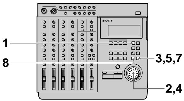
1 Press EDIT.
EDIT appears in the display.
2 Turn the jog dial so that "Disc Name" appears in the display.
The name of the edit function starts blinking in the display.
3 Press ENTER.
The edit setting items appear in the display.
4 Turn the jog dial to display the character you desire.
The selected character blinks. In addition to the letters of the alphabet, you can also use numbers and symbols. The symbols which can be displayed are as follows:
$$ \begin{array}{l} \text {!}" # \% \& ^ {\prime} (\text {) } * +, -. /:; < = >? @ \ \wedge_ {-} ^ {\prime} (\text {blank}) \end{array} $$
5 Press ENTER.
The character selected in step 4 lights steadily and the cursor starts blinking in the next position.
To go back to the previous position, press EXIT.
6 Repeat steps 4 and 5 until to complete the title.
7 Press EXIT when the cursor is in the leftmost position or press ENTER when the cursor is in the rightmost position to enter the final name. To carry out another edit operation in succession use the jog dial to specify the operation you desire.
8 Press EXIT.
This completes the edit operation.
Advantages of Using MIDI
Connecting this unit to an external MIDI system
(Computer, Sequencer, Sound Module, etc.) allows you to create even higher quality recordings.
For example, if you record the vocal and guitar tracks on this unit, you can synchronize them with sounds from a sound module played back through a sequencer (etc.) during mixdown. This method of mixing allows you to make recordings without using unnecessary tracks.
The MTC (MIDI Time Code), MIDI clock, or MMC (MIDI Machine Control) features allow you to coordinate this unit with external MIDI components.
This chapter explains how to use MIDI messages (information) in order to realize the following functions:
- Synchronization with a MIDI sequencer (etc.).
- Remote control PLAY and STOP (etc.) from MIDI components.
MIDI Synchronization Using MTC
The following explains how to achieve synchronization with a MTC (MIDI Time Code) compatible sequencer (etc.).
Connections
Use a MIDI cable to connect this unit to a MIDI compatible sequencer (etc.).
MDM-X4 (this unit)
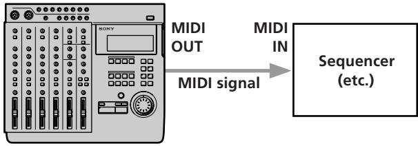
flowchart
graph LR
    A["SONY"] -->|MIDI OUT| B["MIDI IN"]
    A -->|MIDI signal| C["Sequencer (etc.)"]
Setup
1 Set this unit's "SYNC" system setting to MTC. See "Changing a Setting" (page 18) for details.
2 Set the sequencer to accept external MTC synchronization.
This enables playback of MIDI song data.
Refer to the operating instructions supplied with your sequencer as well.
3 Start playback from this unit.
The sequencer starts playing in synchronization with this unit.
MIDI Synchronization Using the MIDI Clock
You can use the MIDI clock to synchronize this unit with sequencers (etc.) that are not MTC (MIDI Time Code) compatible. A tempo map must be created in order to use the MIDI clock.
Notes
- When using the MIDI clock for synchronization, be sure to create the tempo map before you start recording (see "Creating a tempo map" to the right for details). Also, be sure to listen to the MIDI sound source coming from the sequencer before you start recording.
It is extremely difficult to create a perfect match between a recorded song and the timing of the tempo map.
Therefore, if you create a tempo map after recording, the synchronization will be incorrect.
Tempo information will not be stored on the disc if you create a tempo map but do not make an actual recording.
- When using a sequencer that supports MIDI clock and MIDI song position, you can start playback from an arbitrary position in the song. At this time, the sequencer locates the current song position and starts running in sync. Some sequencers, however, may not be able to follow this unit when you use this unit's locate function. Be sure to check the sequencer's search before synchronized operation.
Connections
Use a MIDI cable to connect this unit to a MIDI compatible sequencer (etc.).
MDM-X4 (this unit)
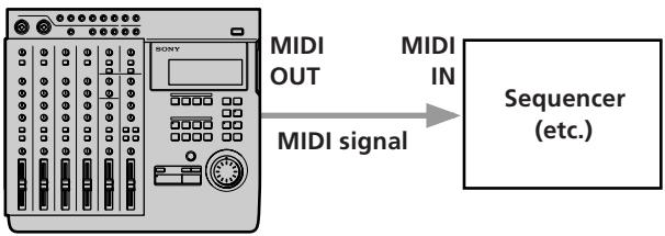
flowchart
graph LR
    A["SONY BOSY"] -->|MIDI OUT| B["MIDI IN"]
    A -->|MIDI signal| C["Sequencer (etc.)"]
Setup
1 Set this unit's "SYNC" system setting to MCLK. See "Changing a Setting" (page 18) for details.
2 Set the sequencer to accept external MIDI clock synchronization.
This enables playback of MIDI song data.
Refer to the operating instructions supplied with your sequencer as well.
3 Start playback from this unit.
The sequencer starts playing in sync with this unit.
Creating a tempo map
Setting up tempo information creates the standard signal for synchronization and allows you to use the MIDI clock for synchronization with an external sequencers (etc.).
You can assign up to 50 tempo maps to each song.
EXAMPLE: Suppose we create the following tempo maps.
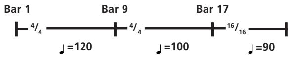
In this case, the tempo will change as shown below
| Bar 1~8 | ^4/_4 time | ♩=120 |
| Bar 9~16 | ^4/_4 time | ♩=100 |
| Bar 17~ | ^16/_16 time | ♩=90 |
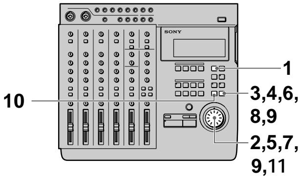
The following step show you how to make the tempo map shown in the previous example.
1 Press EDIT.
EDIT appears in the display.
2 Turn the jog dial so that "Song Tempo" appears in the display.
The name of the edit function starts blinking in the display.
(continued)
3 Press ENTER.
The tempo map setting display appears.
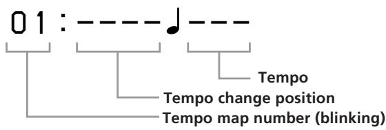
Note
If you do not want to change the tempo information, leave the tempo information numbers blank.
4 Press ENTER again.
The indication for the tempo change position starts blinking.
Tempo map 1 can only be set to the first bar.
5 Turn the jog dial to display 0001.
The units in the display represent bars.
If you hold down SHIFT while turning the jog dial you can specify the tempo change position in 16th note units within the respective bar.
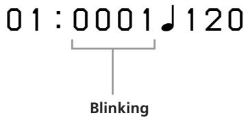
Note
If you do not want to change the tempo information, leave the tempo information numbers blank.
6 Press ENTER.
The indication for the tempo starts to blink.
7 Turn the jog dial to display 120.
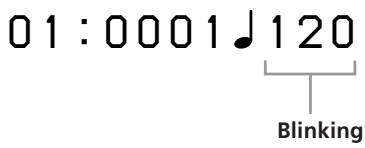
8 Press ENTER.
The time setting display appears.
9 Use the jog dial and ENTER to display 04/04.
01:04/04
10 Press ENTER again when finished.
The tempo map number blinks.
11 Turn the jog dial to display 02.
12 Repeat steps 3\~9 to create the new tempo map. When the tempo map is complete, the settings are displayed in order automatically starting from the first tempo change position.
To complete construction of the tempo map
Press EXIT repeatedly until the EDIT display disappears from the display.
Notes
- The time setting is only possible at the beginning of each bar.
- You can assign up to 50 tempo maps to each song. The tempo information can be stored on the disc, but since there is a limited amount of memory on each disc it may not be possible to store 50 tempo maps for each song if there are several songs on a disc. In this case “Tempo Full” will appear in the display when you select the tempo map number.
- Due to the nature of the MD system, MIDI clock information cannot be output and tempo information cannot be stored when using standard music MD discs.
Deleting a tempo map
Use the following operations to delete tempo maps which are no longer necessary. The tempo map numbers located after the tempo map which was deleted are brought forward automatically.
EXAMPLE: Erasing tempo map 5.
1 Press EDIT.
EDIT appears in the display.
2 Turn the jog dial so that "Song Tempo" appears in the display.
The name of the edit function starts blinking in the display.
3 Press ENTER.
The tempo map setting display appears.
4 Turn the jog dial to display tempo map 05.

Blinking
5 Press ENTER.
The indication for the tempo change position starts blinking.
Tempo map 1 can only be set to the first bar.
6 Turn the jog dial to the right to display Del.
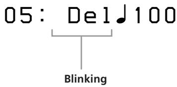
7 Press ENTER.
"Deleted" appears in the display and tempo map 5 is deleted.

The previous operations can also be used to delete tempo map 1. However, tempo map 1 should only be deleted after deleting all the other tempo maps from 2 up.
Controlling This Unit from Other MIDI Components Using MMC
You can control this unit from MMC (MIDI Machine Control) compatible external MIDI equipment, such as a sequencer (etc.).
Connections
Use a MIDI cable to connect this unit to a MIDI compatible sequencer (etc.).
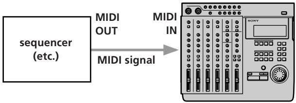
flowchart
graph LR
    A["sequencer (etc.)"] -->|MIDI OUT| B["MIDI signal"]
    B --> C["MIDI IN"]
    C --> D["SONY"]
Setup
Set this unit's "MMC" system setting to "on".
See "Changing a Setting" (page 18) for details.
This unit accepts the following MMC command/responses:
- Stop (Command 01): Stops the disc. Reception of this command during recording (or rehearsal) will cause recording (rehearsal) to stop.
- Play (Command 02,03) : Starts playback. Reception of this command during recording (or rehearsal) will not cause recording (rehearsal) to stop.
- Fast Forward (FF) (Command 04): Fast forward. Reception of this command during recording (or rehearsal) will cause recording (rehearsal) to stop.
- Rewind (REW) (Command 05): Rewind. Reception of this command during recording (or rehearsal) will cause recording (rehearsal) to stop.
- Record Strobe (Command 06) : During playback, it starts recording on the recordable track (the track selected with the REC SELECT key). During stop mode, it starts recording (or rehearsal) on the recordable track. Reception of this command during modes not listed above (pause mode, etc.) has no effect on the unit.
- Record Exit (Command 07) : Stops recording on all tracks.
- MMC Reset (Command 0D) : Resets MMC related information to the state it was in at power on.
- Write (Command 40,41): Writes or changes data in the specified information field (for Track Record Ready only).
- Locate (Command 44): Locates the specified time code.
- Group (Command 52) : Checks the device ID list to see whether or not the unit belongs to the current group. If it belongs to the group, that group ID is used to receive MMC data. This unit can store up to 16 IDs.
- Track record ready (Response 4F) : Turns REC SELECT on/off.
Example of a MIDI System
The following explains the construction of a synchronized MIDI system using both MMC and MTC and a MIDI sound module.
Connections
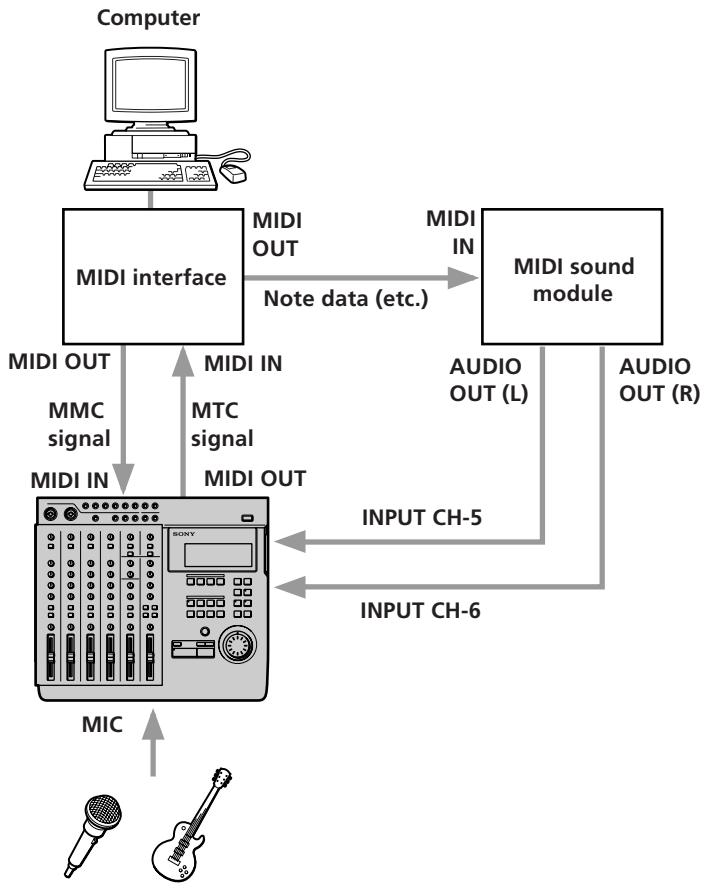
flowchart
graph TD
    A["Computer"] --> B["MIDI interface"]
    B -->|Note data (etc.)| C["MIDI sound module"]
    C -->|AUDIO OUT (L)| D["OUTPUT CH-5"]
    C -->|AUDIO OUT (R)| E["OUTPUT CH-6"]
    B -->|MIDI IN| F["MIDI OUT"]
    B -->|MTC signal| G["MIDI IN"]
    F --> H["MIC"]
    G --> I["MIC"]
    H --> J["SONY"]
    I --> K["SONY"]
Features available from this type of system
- You can record live vocal and guitar tracks (acoustic sounds) on this unit and then use MIDI sound control to play them in sync with other sounds played back through a sequencer (etc.).
- You can use MTC to synchronize a sequencer (etc.) with this unit.
- You can use MMC to control this unit from a sequencer (etc.).
Mixdown (Basics)
The following explains how to dub the song to a master recorder (such as a DAT or MD recorder) while adjusting the volume balance and localization of each track once you have completed all necessary recording and editing.
This process, of completing a song composed in 4 tracks by converting it to normal stereo (2 tracks), is called “mixdown”.
This process is generally considered the most important part of music production.
Preparations
- Connect the master recorder to this unit's STEREO OUT jacks. If necessary, you can connect an effector between this unit and the master recorder.
- If you are planning to simultaneously mixdown sound from a MIDI sound source by synchronizing with external MIDI equipment, be sure to make all necessary connections and settings beforehand.
See “Synchronization with MIDI Equipment” (pages 52 \~ 56) for details.
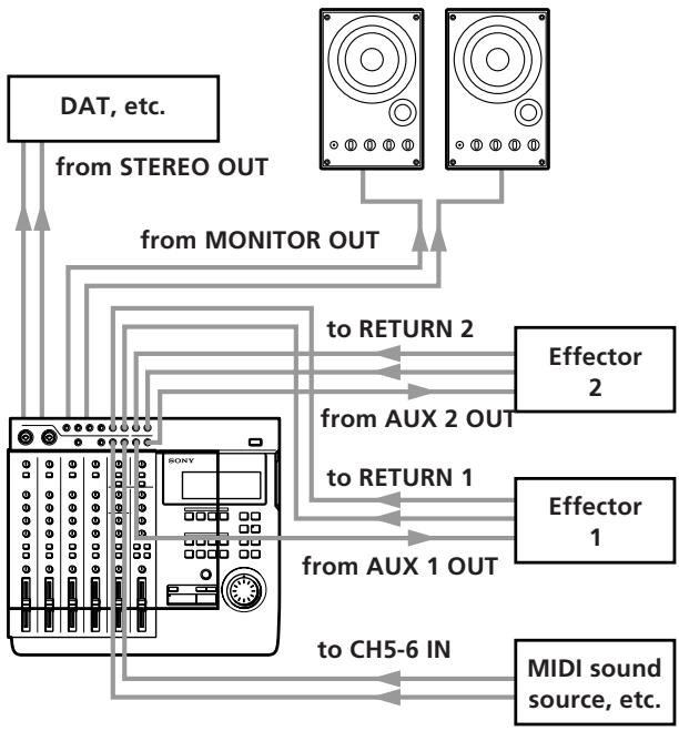
flowchart
graph TD
    A["DAT, etc."] -->|from STEREO OUT| B["Monitor Out"]
    C["Speaker 1"] -->|to RETURN 1| D["Effector 1"]
    E["Speaker 2"] -->|to RETURN 2| F["Effector 2"]
    G["Speaker 3"] -->|to CH5-6 IN| H["MIDI sound source, etc."]
    B --> I["Tochamber"]
    F --> I
    H --> I
    I --> J["Tochamber"]
Carrying out the mixdown
1 Press down the INPUT switches on channels 1\~4. (Set channels 1\~4 to receive the (TRACK) sound played back from the recorder.)
2 Press the monitor tracks STEREO key.
3 Use the ◀◀◀ or ▶▶◀ keys or the jog dial to locate the beginning of the desired song.
4 Press ▶ PLAY.
Playback begins.
5 Playback the track as many times as necessary to make the following adjustments.
Volume balance : Adjust using the faders on channels 1\~4 and the MASTER fader. If an external MIDI sound source is being input to channel 5/6, adjust using the channel 5/6 fader as well.
Localization : Adjust using the PAN knobs on channels 1\~4.
Effect volume : When an effector is connected, use the AUX or RETURN knobs to adjust the proportion of the effect.
6 After completing the adjustments, make the recording on the master recorder.
Be sure to check the recording level on the master recorder and make any necessary adjustments.
When the recording has finished, mixdown is complete.
Mixdown (Applied Operations)
How to use the TRACK jacks
The TRACK 1\~4 jacks on the top panel of this unit provide a direct output of the signals from each track recorded on the disc. This allows you to take full advantage of a limited number of external effectors.
EXAMPLE: After recording a vocal on track 1 and a keyboard on track 2.
- You want to add delay to the vocals.
- You want to add flanging to the keyboard.
- But you only have 1 effector.
This kind of situation is where you can use the TRACK jacks.
For this example, we will explain how to record the vocal recorded on track 1 back to track 1 while adding delay.
1 Connect this unit's TRACK 1 OUTPUT jack to the input jack on the effector, and connect the output jack on the effector to this unit's INPUT CH 1 jack.
2 Set the INPUT switch for channel 1 to LINE/MIC (pressed down).
3 Play the track and adjust the effector volume. During the actual recording, the direct sound will be rerecorded after it passes through the effector.
4 After completing the adjustments, record to track 1.
This operation can be performed for any track by using the respective input jack.

- By connecting the TRACK OUT jack to the effector and then inputting that sound to one of this unit's other INPUT CH jacks, you can mix the source and mix sounds with different equalizations.
- By using all four of the TRACK OUTPUT jacks, you can dub all 4 tracks independently to another multichannel recorder.
How to save up to 8 tracks of data independently
You can record sound parts numbering greater than the number of tracks available on this unit (4) by using the bounce recording function (page 29).
However, some of the features available during the normal bounce operation, such as rerecording the sound from the track being mixed to, and changing the mix balance, are not possible during this operation.
But, you can rely on the wide variety of editing functions available with this unit.
Since this unit can edit individual tracks (as well as songs), you can store more than 4 tracks worth of data individually and reedit them whenever necessary.
The following is an explanation of the example.
1 Recording the drums in stereo to tracks 1 and 2, then overdub the bass and guitar. (Song 1)
Song 1
| 1 | Dr (L) |
| 2 | Dr (R) |
| 3 | B |
| 4 | G |
2 Use the Song Copy edit function to back up the part recorded in step 1.
The backup becomes Song 2.
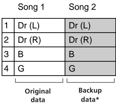
* Since this is a digital copy, there is no deterioration of the data when the copy is made.
3 Use mix write recording to mixdown tracks 1 and 2 of Song 1 to track 4 of Song 1.
Song 1
Song 2
| 1 | Dr (L) +B+G | Dr (L) |
| 2 | Dr (R) | Dr (R) |
| 3 | B | |
| 4 | G |
4 Overdub the keyboard in stereo to tracks 3 and 4 while listening to the playback from tracks 1 and 2. (Song 1)
Song 1 Song 2
| 1 | Dr (L)Dr (R)+B+G | Dr (L) |
| 2 | Dr (R) | |
| 3 | K (L) | B |
| 4 | K (R) | G |
5 Use the Song Copy edit function to back up the keyboard part.
The backup becomes Song 3.
Song 1 Song 2 Song 3
| 1 | Dr (L) | Dr (L) | Dr (L) |
| Dr (R) | Dr (R) | Dr (R) | |
| 2 | |||
| 3 | K (L) | B | K (L) |
| 4 | K (R) | G | K (R) |
6 Use bounce recording to mixdown all four parts to tracks 1 and 2. (Song 1)
Song 1 Song 2 Song 3
| 1 | Dr+K(L)Dr+K(R)+B+G | Dr (L) | Dr (L)Dr (R)+B+G |
| 2 | Dr (R) | ||
| 3 | B | K (L) | |
| 4 | G | K (R) |
7 Overdub the vocals to tracks 3 and 4 while listening to the playback from tracks 1 and 2. (Song 1)
Song 1 Song 2 Song 3
| 1 | Dr+K(L)Dr+K(R)+B+G | Dr (L) | Dr (L)Dr (R)+B+G |
| 2 | Dr (R) | ||
| 3 | Vo 1 | B | K (L) |
| 4 | Vo 2 | G | K (R) |
8 Use the Song Copy edit function to back up the vocals, then copy tracks 3 and 4 to tracks 1 and 2. This process allows you mixdown while to preserving the sound of all the original parts.
Song 1 Song 2 Song 3
| 1 | Dr+K(L) +B+G | Dr (L) | Vo 1 |
| 2 | Dr+K(R) | Dr (R) | Vo 2 |
| 3 | Vo 1 | B | K (L) |
| 4 | Vo 2 | G | K (R) |
Completed Mix Backup of individual parts

- For future reference, we recommend naming each song in a way that helps you remember the content of the individual tracks. (Use the Song Name edit operation).
- Later, you can use the backed up songs to create remixes. With the method described in the previous example, you can use [Song Copy] to create a new copy of the tracks in songs 2 and 3 as song 4. This allows you to create new mixes later.
Troubleshooting
If this unit does not operate as expected, the problem may simply be an oversight, a disconnected cable or a setting error. Before calling a service technician, compare the symptoms of the problems with those listed below to see if you can correct the problem yourself.
Operation is not possible
→ The disc is dirty or damaged, replace it with a new one.
Playback is not possible
→ Condensation has formed inside the cabinet, remove the disc and leave this unit's power on for a few hours.
→ Turn on the power.
→ Insert the disc in accordance with the direction of the arrow on the disc case.
→ Nothing has been recorded on the current disc. Load a disc that has been recorded.
Recording is not possible
The disc has write protected to prevent accidental recording (“Protected” is displayed). Slide the protect tab back into place to cover the hole on the side of the disc.
→ The source is not connected correctly. Recheck all connections.
→ The recording level is too low. Use the TRIM knob to adjust the recording level.
→ Replace the current disc with one that can be recorded on.
→ Replace the current disc with one that has enough time left, or erase unnecessary songs.
→ If the power cord was unplugged during recording, or there was a power outage, the recording up to that point may be lost. If recording was not completed normally, try recording again starting from the beginning.
Excessive noise
→ Place this unit away from televisions and other equipment.
Display Message List
This unit uses the display area to show operating condition and error messages. The meaning of each message is explained below.
Battery Low
The internal battery is low.
Take the unit to an authorized service station and request a battery replacement.
Blank Disc
An unrecorded MD or MD which has been erased is loaded.
Disc Error
An abnormal or damaged MD, whose TOC cannot be read (etc.) is loaded. The loaded disc cannot be used with this unit.
Disc Full
Recording is not possible because there is no time remaining on the disc.
Error\*\*
A serious error has occurred. Please contact a Sony service station.
Invalid
An operation was canceled due to an invalid setting, or the processing of an edit command was canceled midway.
Recheck the settings or try performing the same operation again.
Loading
The disc is currently being loaded.
Name Full
No more song or disc name characters can be entered. (Approximately 1700 characters have already been entered.)
No disc
No disc loaded in this unit.
Processing
The unit is writing data or performing an edit operation.
Protected
The currently loaded disc is write protected. Or, a disc that cannot be recorded on has been loaded, such as a read only disc (etc.).
Retry Error
Normal recording was not possible because vibrations or a scratched disc (etc.) caused repeated rewriting.
Toc Reading
The unit is reading the TOC data from the disc.
Toc Writing
The unit is writing the TOC data to the disc.
Tempo Full
No more tempo information can be input.
Unloading
The unit is ejecting the disc.
System Limitations of MDs
The recording system in your MD deck has limitations described below. Note, however, that these limitations are due to the inherent nature of the MD recording system itself and not to mechanical causes.
"DISC FULL" lights up before the MD has reached the maximum recording time (60 or 74 minutes)
When 255 songs have been recorded on the MD, “DISC FULL” lights up regardless of the total recorded time. More than 255 songs cannot be recorded on the MD. To continue recording, erase unnecessary songs or use another recordable MD.
"DISC FULL" lights up before the maximum number of songs (255) is reached
Fluctuations in emphasis within songs are sometimes interpreted as song intervals, increasing the song count and causing “DISC FULL” to light up.
"TOC Reading" is displayed continuously
The “TOC Reading” display lasts longer than usual when a brand new disc is inserted.
The total recorded time and the remaining time on the MD do not total to the maximum recording time
This unit displays the length of the largest continuous blank area as the remaining time. Therefore, if there are several separate blank spaces, the remaining time will only display a time equivalent to the largest continuous blank space. If there is a 1 minute blank space and a 2 minute blank space, the remaining time display will be “2” minutes. If you then record 1 minute and 30 seconds of the 2 minute blank, the remaining time display will become “1” minute.
It is not possible to make new recordings on a song which was modified using the Section Edit or Song Combine functions
In this case copy the entire song (using Song Copy), then perform the desired recording or edit operation on the new copy of the song.
It is not possible to shorten part of a song using the Section Edit or Song Edit functions
This unit organizes the audio data in sound groups and clusters. The minimum size of these units varies according to the number of tracks specified in the system setting (page 17). With 4 tracks, units may not be less than approximately 4 seconds. With 2 tracks, units may not be less than approximately 8 seconds. With 1 track, units may not be less than approximately 16 seconds.
Discs with Emphasis information are not properly De-emphasized during playback.
During playback and recording, this unit always handles emphasis information as if it were turned "OFF".
Unit enters the play/pause mode between songs during continuous playback.
This unit enters the play/pause mode momentarily before resuming playback each time it reaches a new song number or division created using Song Divide.
Specifications
Mixer Section
System (10 channel input mixer)
Internal bus
Group x 4, Stereo x 2, Monitor x 2, AUX x 2
Channel 1\~4
Trim, Input Select, EQ (High/Mid/Low), AUX Out, Bus Assign Select, Panpot, Channel Fader
Channel 5\~6
EQ (High/Low), Bus Assign Select, Balance
Master
Master Fader
Return 1\~2
Return Level, Bus Assign Select
Aux 1\~2 Send
Master Level
Monitor
Monitor Select, Monitor Level, Track 1\~4 Level
INPUTS
CH1/2
Type : XLR-3-31/Phone (Balanced)
Input impedance : greater than 20 kohm
Standard input level: -50 -10 dBs (Max: + 10dBs)
XLR type (Balanced)
flowchart
graph TD
    A["1"] --> B["2"]
    B --> C["3"]
    C --> A
① : GND
② : HOT
③ : COLD
Phone type (Balanced)
Sleeve : GND
Tip : HOT
Ring : COLD
CH3/4
Type : Phone (Unbalanced)
Input impedance : greater than 20 kohm
Standard input level: -50 -10 dBs (Max: + 10dBs)
CH5/6
Type : Phone (Unbalanced)
Input impedance : greater than 20 kohm
Standard input level: -10 dBs (Max: + 10dBs)
RETURN 1\~2 (L/R)
Type : Phone (Unbalanced)
Input impedance : greater than 20 kohm
Standard input level: -10 dBs (Max: + 10dBs)
OUTPUTS
STEREO OUT (L/R)
Type : Phono (Unbalanced)
Load impedance : greater than 20 kohm
Standard output level: -10 dBs
MONITOR OUT (L/R)
Type : Phono (Unbalanced)
Load impedance : greater than 20 kohm
Standard output level: -10 dBs
TRACK OUT (1\~4)
Type : Phone (Unbalanced)
Load impedance : greater than 20 kohm
Standard output level: -10 dBs
AUX OUT (1\~4)
Type : Phone (Unbalanced)
Load impedance : greater than 20 kohm
Standard output level: -10 dBs
CHANNEL EQUALIZER
CH 1\~4
Low : ±15 dB (at 50 Hz)
Mid : ±12 dB (at 2.5 kHz)
High : ±15 dB (at 15 kHz)
CH 5\~6
Low : ±15 dB (at 50 Hz)
High : ±15 dB (at 15 kHz)
* 0dBs = 0.775 Vrms
Recorder Section
Controls
Rec Select : 1\~4
Locate Control : Mark, In, Out, Shift, A, B, C, D
Function : Edit, System, Repeat, Rehearsal, Auto Punch,
Undo, Exit, Enter, Top, Rec, AMS (x 2), Play, Stop, Jog/
Shuttle, Eject
System
MD-DATA system, Mini Disc digital audio system
Disc
MD Data disc, MD audio disc
Sampling Frequency
44.1 kHz
Maximum Recording Length
Max. 37 minutes (4 tracks / using MD Data disc)
Max. 74 minutes (2 tracks)
Max. 148 minutes (monaural)
Number of tracks that can be recorded simultaneously
Max 4 tracks (using MD Data disc)
Max 2 tracks (using MD audio disc)
Frequency response
5 \~ 20,000 Hz ±1.0 dB
Signal to noise ratio
More than 94 dB during playback
Maximum song number
255
Pitch control
±8.0%
Control jacks
Assignable switch x 2
Wow and flutter
Below measurable limit
Recording method
Magnetic field variation overwrite
Reading method
Non-contact Optical pickup (using Semiconductor laser)
Laser
Semiconductor laser ( =780nm )
Revolutions
Approx. 400\~900 rpm (CLV)
Error correction
Advanced Cross Interleave Reed Solomon Code (ACIRC)
Coding
Adaptive TRansform Acoustic Coding (ATRAC)
Modulation
EFM (Eight-to-Fourteen Modulation)
Smallest edit increment
approx. 11.6 msec
General
Power Source
AC 120 V, 60 Hz
AC 230 V, 50/60 Hz
Power Consumption
25 W (120 V)
27 W (230 V)
Dimensions
423 x 119 x 385 mm (W x H x D including projections)
Mass
Approx. 5.1 kg
Supplied Accessories
Operating instructions (1)
U.S. and foreign patents licensed from Dolby Laboratories Licensing Corporation.
Design and specifications subject to change without notice.
Glossary
TOC (Table of Contents)
The area in which nonmusical data, such as disc and track information is stored. Writing of TOC information marks the completion of record and edit operations.
ATRAC (Adaptive TRansform Acoustic Coding)
ATRAC is the sound compression technology that enables an MD to contain the same length of music as a CD, despite the smaller physical size of the MD. ATRAC cuts the sounds imperceptible by the human ear to compress the data to 1/5 the original size. Since the data is chosen for reduction is based on psychoacoustic principles there is no perceivable effect on the sound quality.
EQ
Abbreviation for equalizer. Adjusts certain bands of the sound. This unit has treble (HIGH), middle (MID), and bass (LOW) adjustments. See “Names and Function of Parts” (page 6) for details.
PAN
Abbreviation for pan pot. Adjusts the position of the sound. See “Names and Function of Parts” (page 7) for details.
MIDI (Musical Instrument Digital Interface)
A worldwide standard for data transmission between electronic instruments.
MMC (MIDI Machine Control), MTC (MIDI Time Code)
See “Synchronization with MIDI Equipment” (pages 52\~56).
Bus
Transports the input or recorded sounds to a specific section. The group bus (1\~4) carries the sound to the respective tracks in the recorder, the stereo bus (L and R) carries the sound to the STEREO OUT jacks, and the CUE bus carries the sound recorded on the tracks to the MONITOR OUT jacks.
Blank Top
The first section of the unrecorded portion of the disc. It is necessary to locate the blank top when recording a new track on a disc that contains previously recorded material. For this unit, press the TOP key twice to locate the blank top. "New Song" appears in the display.
Ping Pong Recording
Normally, this term refers to the practice of dubbing the sound from tracks 1 through 3 onto track 4 in order to gain additional tracks. With this unit, you can dub the sound from tracks 1 through 4 to track 4. See “Mix Write Recording (Applied Operations)” (page 28) for details.
Punch-In/Out Recording
Recording only part of a given track. Normally used to correct a performance mistake by rerecording the part which was mistaken, or to record only one phrase of a song. See “Auto Punch-In/Out Recording” (page 22) and “Manual Punch-In/Out Recording” (page 25) for details.
Overdub Recording
Listening to the sound from one previously recorded track while recording onto another track. See "Overdub Recording" (page 20) for details.
Bounce Recording
Recording the sounds previously recorded on tracks 1\~4 in a stereo mix to tracks 1 and 2. See “Mix Write Recording (Applied Operations)” (page 28) for details.
Mixdown
Dubbing the 4 track sound to two track equipment (such as a DAT) while adjusting the balance.
MD-DATA and Mini Disc
Mini Disc (MD) is a format developed specifically for music storage. The MD-DATA format was developed for data storage. This unit uses MD-DATA format (recordable) discs for 4 track recording and playback. For recording and playback of 2 tracks (or less) you can use either MD-DATA or Mini Disc formats. Please note that, however, that Mini Disc and MD-DATA are two different formats and are not interchangeable.
MD-DATA format discs bear the following logo:

DATA
Mini Disc format discs bear the following logo:

Note regarding usage of discs with different formats
If an MD-DATA disc containing data written in another format (such as Picture MD, etc.) is inserted into this unit, “Blank Disc” appears in the display and the disc will seem to be a blank disc (regardless of data present in other formats). If you use a variety of different formats, keep your discs well organized to prevent accidental erasure.
Block Diagram
The block diagram for this unit is shown below.
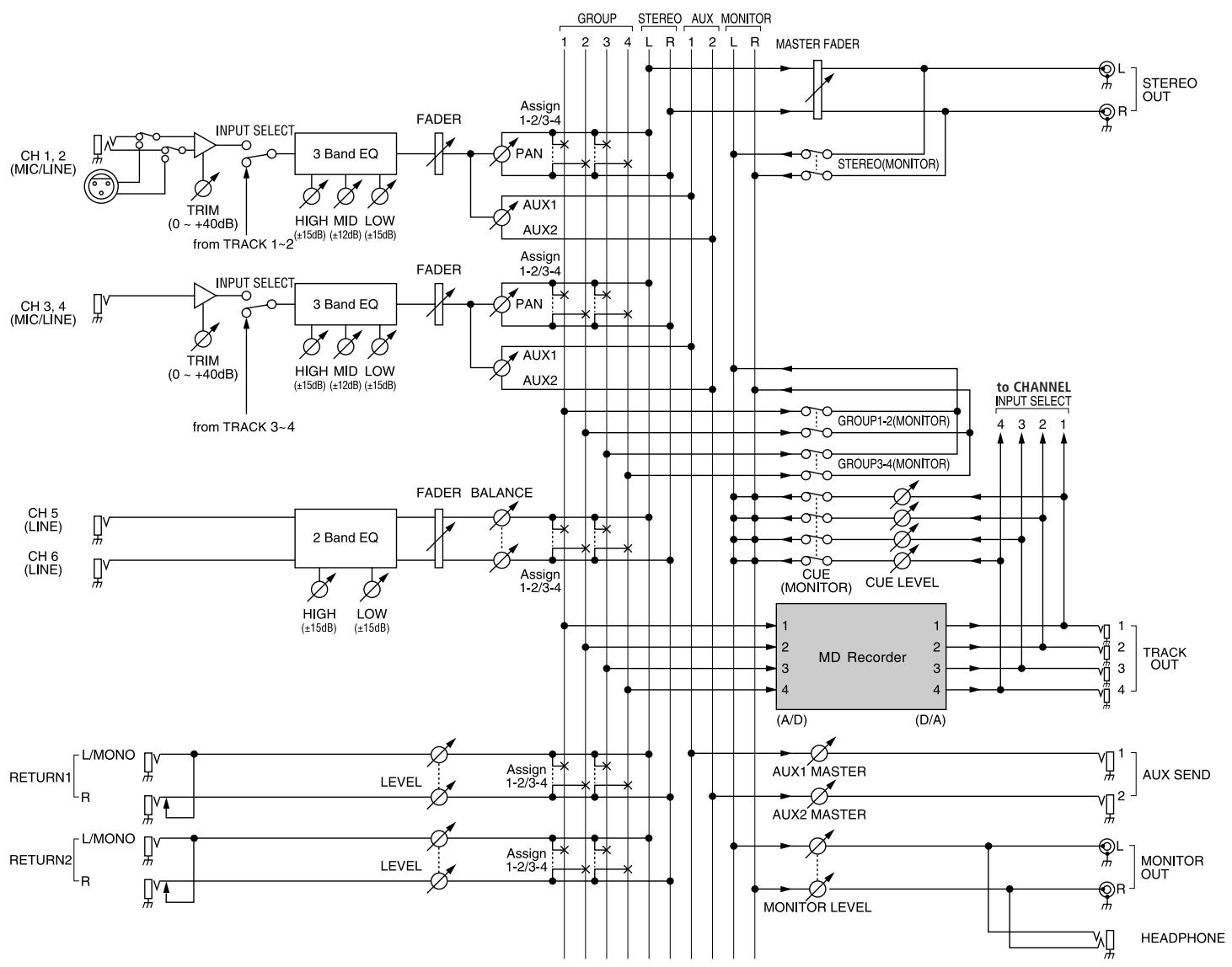
flowchart
graph TD
    subgraph_Channel_1["CH 1,2 (MIC/LINE)"]
        A["TRIM (0 ~ +40dB)"] --> B["INPUT SELECT"]
        B --> C["3 Band EQ"]
        C --> D["FADER"]
        D --> E["PAN"]
        E --> F["AUX1 AUX2"]
        F --> G["AUX1 AUX2"]
        G --> H["ASSIGN 1-2/3-4"]
        H --> I["PAN"]
        I --> J["AUX1 AUX2"]
    end

    subgraph_Channel_2["CH 3,4 (MIC/LINE)"]
        K["TRIM (0 ~ +40dB)"] --> L["INPUT SELECT"]
        L --> M["3 Band EQ"]
        M --> N["FADER"]
        N --> O["PAN"]
        O --> P["AUX1 AUX2"]
        P --> Q["AUX1 AUX2"]
    end

    subgraph_Channel_3["CH 5 (LINE)"]
        R["CH 6 (LINE)"] --> S["2 Band EQ"]
        S --> T["FADER BALANCE"]
        T --> U["ASSIGN 1-2/3-4"]
        U --> V["AUX1 AUX2"]
    end

    subgraph_Channel_4["CH 5 (LINE)"]
        W["RETURN1"] --> X["L/MONO R"]
        Y["RETURN2"] --> Z["L/MONO R"]
    end

    subgraph_Channel_5["CH 5 (LINE)"]
        AA["RETURN1"] --> AB["L/MONO R"]
        AC["RETURN2"] --> AD["L/MONO R"]
    end

    subgraph_Channel_6["CH 6 (LINE)"]
        AE["RETURN1"] --> AF["L/MONO R"]
        AG["RETURN2"] --> AH["L/MONO R"]
    end

    subgraph_Channel_7["MD Recorder"]
        AI["AUX1 MASTER"] --> AJ["AUX2 MASTER"]
        AK["AUX1 MASTER"] --> AL["AUX2 MASTER"]
        AM["AUX1 MASTER"] --> AN["AUX2 MASTER"]
        AO["AUX1 MASTER"] --> AP["AUX2 MASTER"]
        AQ["AUX1 MASTER"] --> AR["AUX2 MASTER"]
        AS["AUX1 MASTER"] --> AT["AUX2 MASTER"]
        AU["AUX1 MASTER"] --> AV["AUX2 MASTER"]
        AW["AUX1 MASTER"] --> AX["AUX2 MASTER"]
        AY["AUX1 MASTER"] --> AZ["AUX2 MASTER"]
        BA["AUX1 MASTER"] --> BB["AUX2 MASTER"]
        BC["AUX1 MASTER"] --> BD["AUX2 MASTER"]
        BE["AUX1 MASTER"] --> BF["AUX2 MASTER"]
        BG["AUX1 MASTER"] --> BH["AUX2 MASTER"]
        BI["AUX1 MASTER"] --> BJ["AUX2 MASTER"]
        BK["AUX1 MASTER"] --> BL["AUX2 MASTER"]
        BM["AUX1 MASTER"] --> BN["AUX2 MASTER"]
        BO["AUX1 MASTER"] --> BP["AUX2 MASTER"]
        BQ["AUX1 MASTER"] --> BR["AUX2 MASTER"]
        BS["AUX1 MASTER"] --> BT["AUX2 MASTER"]
        BU["AUX1 MASTER"] --> BV["AUX2 MASTER"]
        BW["AUX1 MASTER"] --> BX["AUX2 MASTER"]
        BYA["AUX1 MASTER"] --> BZ["AUX2 MASTER"]
        CA["AUX1 MASTER"] --> CB["AUX2 MASTER"]
        CC["AUX1 MASTER"] --> CD["AUX2 MASTER"]
        DEA["AUX1 MASTER"] --> DF["AUX2 MASTER"]
        DG["AUX1 MASTER"] --> DH["AUX2 MASTER"]
        DI["AUX1 MASTER"] --> DJ["AUX2 MASTER"]
        DKA["AUX1 MASTER"] --> DL["AUX2 MASTER"]
        DM["CUE (MONITOR)"] --> DN["CUE LEVEL"]
    end

    subgraph_Channel_8["TO CHANNEL INPUT SELECT"]
        DO["GROUP"] --> DO
        DO_R["STREEO"] --> DO_R
        DO_L["ASSIGN 1-2/3-4"] --> DO_R
        DO_R_R["ASSIGN 1-2/3-4"] --> DO_L_R
    end

    subgraph_Channel_9["TRACK OUT"]
        DO_R_R["STREEO(MONITOR)"] --> DO_R_R
    end

    subgraph_Channel_10["MONITOR OUT"]
        DO_R_R["R"] --> DO_R_R
    end

    subgraph_Channel_11["HEADPHONE"]
        DO_R_R["R"] --> DO_R_R
    end
Sony Multi Track Recorder MDM-X4 MIDI Implementation Chart
SEP 21, 1996 Version: 1.0
| Function... | Transmitted | Recognized | Remarks | ||
| Basic Channel | Default Changed | X X | X X | ||
| Mode | Default Messages Altered | X X * * * * * * * * * * * * * * * * * * * * * * * * * * * * * * * * * * * * * * * * * * * * * * * * * * * * * * * * * * * * * * * * * * * * * * * * * * * * * * * * * * * * * * * * * * * * * * * * * * * * | |||
| Note Number: | True Voice | X * * * * * * * * * * * * * * * * * * * * * * * * * * * * * * * * * * * * * * * * * * * * * * * * * * * * * * * * * * * * * * * * * * * * * * * * * * * * * * * * * * * * * * * * * * * * * * * * * * * 10000000000000000000000000000000000000000000000000000000000000000000000000000000000000000000000000000 | |||
| Velocity | Note ON Note OFF | X X | X X | ||
| After Touch | Key's Ch's | X X | X X | ||
| Pitch Bend | X | X | |||
| Control Change | 0 - 31, 64 - 120 | X | X | ||
| Prog Change : True# | X * * * * * * * * * * * * * * * * * * * * * * * * * * * * * * * * * * * * * * * * * * * * * * * * * * * * * * * * * * * * * * * * * * * * * * * * * * * * * * * * * * * * * * * * * * * * * * * * * | ||||
| System Exclusive | X | O^*2 | |||
| Common : Quarter Frame : Song Pos : Song Sel : Tune | O^*1 O^*3 O^*3 X | XXX | |||
| System Real Time : Clock : Commands | O^*3 O^*3 | XX | |||
| Aux Messages : Local ON/OFF : All Notes OFF : Active Sense : Reset | XXXX | XXX | |||
| Notes | *1 : Only when "Sync = MTC".*2 : Supported by MMC (MIDI Machine Control).*3 : Only when "Sync = MCLK". | ||||
Sony MDM-X4 Track Sheet
| Title | |
| Date | |
| Note |
| Song No. (Time) | Track No. | |||
| 1 | 2 | 3 | ||
AVERTISSEMENT
line
| Frequency (Hz) | Series 1 | Series 2 | Series 3 | Series 4 | Series 5 | | -------------- | -------- | -------- | -------- | -------- | -------- | | 20 | 17.0 | 16.0 | 15.0 | 14.0 | 13.0 | | 100 | 10.0 | 9.0 | 8.0 | 7.0 | 6.0 | | 1k | 5.0 | 4.0 | 3.0 | 2.0 | 1.0 | | 10k | -5.0 | -4.0 | -3.0 | -2.0 | -1.0 | | 20k | -20.0 | -18.0 | -16.0 | -14.0 | -12.0 |natural_image
Diagram of a computer monitor base with labeled ports (no text or symbols beyond labels)1 Prise de casque HEADPHONES
2 Prises ASSIGN SW 1,2
Réglage Pre-roll/Post-roll (Roll)
La lecture commence.
Pour réenregistrer
Enregistrement "punch-in/out" manuel
La lecture commence.
Pour réenregistrer
La lecture commence.
La lecture commence.
La lecture commence.
La lecture commence.
flowchart
graph TD
    A["Point IN"] --> B["A"]
    B --> C["B"]
    C --> D["C"]
    D --> E["D"]
    E --> F["Point out"]
    F --> G["Point de destination"]
    G --> H["Final state with C, D, A, B"]
Préparatifs
Effacement de section (Section Delete)
line
| Measure | Value | |---|---| | Measure 1 | 4/4 | | Measure 9 | 4/4 | | Measure 17 | 16/16 | | J = 120 | | | J = 100 | | | J = 90 | |- Track record ready (Réponse 4F): Met REC SELECT en/hors service.
La lecture commence.
Mixdown (applications)
| 1 | Dr (L) +B+G | Dr (L) |
| 2 | Dr (R) | Dr (R) |
| 3 | K (L) | B |
| 4 | K (R) | G |
| 1 | Dr (L) +B+G | Dr (L) | Dr (L) +B+G |
| 2 | Dr (R) | Dr (R) | Dr (R) |
| 3 | K (L) | B | K (L) |
| 4 | K (R) | G | K (R) |
Trim, Input Select, EQ (High/Mid/Low), AUX Out, Bus Assign Select, Panpot, Channel Fader
Canaux 5 et 6
EQ (High/Low), Bus Assign Select, Balance
Master
Master Fader
Retours 1 et 2
Return Level, Bus Assign Select
Monitor Select, Monitor Level, Track 1-4 Level
Entrées
CH1/2
flowchart
graph TD
    A["1"] --> B["2"]
    B --> C["3"]
    C --> A
① : Terre
② : Conducteur
③ : Neutre
Locate Control : Mark, In, Out, Shift, A, B, C, D
Function : Edit, System, Repeat, Rehearsal, Auto Punch,
Undo, Exit, Enter, Top, Rec, AMS (x2), Play, Stop, Jog/
Shuttle, Eject
Système
Minidisque MD-DATA, minidisque MD audio
Dimensions (approx.) (l/h/p)
423 x 119 x 385 mm saillies et commandes comprises
Poids (approx.)
5,1 kg
Accessoires fournis
Mode d'emploi (1)
ATRAC (Adaptive TRansform Acoustic Coding)
① REC SELECT 1 - 4-Tasten
natural_image
Diagram of a computer monitor base with labeled ports (no text or symbols beyond labels 1 and 2)1 HEADPHONES-Buchse
Pre-roll/Post-roll-Zeit (Roll)
Switching songs 2 and 4.
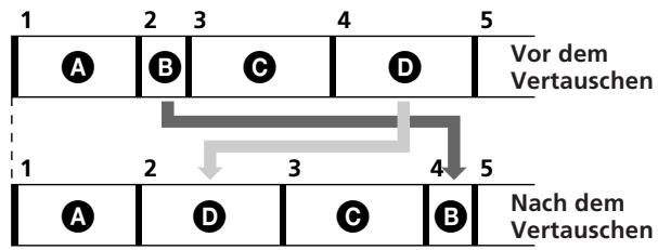
flowchart
graph TD
    A["A"] --> B["B"]
    B --> C["C"]
    C --> D["D"]
    D --> E["Vor dem Vertauschen"]
    E --> F["1"]
    F --> G["2"]
    G --> H["3"]
    H --> I["4"]
    I --> J["5"]
    J --> K["Nach dem Vertauschen"]
    K --> L["A"]
    L --> M["D"]
    M --> N["C"]
    N --> O["B"]

| 1 | Dr (L) +B+G | Dr (L) |
| 2 | Dr (R) | Dr (R) |
| 3 | B | |
| 4 | G |
| 1 | Dr (L)Dr (R)+B+G | Dr (L) |
| 2 | Dr (R) | |
| 3 | K (L) | B |
| 4 | K (R) | G |
| 1 | Dr (L) +B+G | Dr (L) | Dr (L) +B+G |
| 2 | Dr (R) | Dr (R) | Dr (R) |
| 3 | K (L) | B | K (L) |
| 4 | K (R) | G | K (R) |
flowchart
graph TD
    A["1"] --> B["2"]
    B --> C["3"]
    C --> A
Locate Control: Mark, In, Out, Shift, A, B, C, D
Punch, Undo, Exit, Enter, Top, Rec, AMS (x2), Play,
Stop, Jog/Shuttle, Eject
System
EFM (Eight-to-Fourteen Modulation)
Kleinster Editierschritt
ca. 11,6 ms