
DPS-V55M - Audio System SONY - Free user manual and instructions
Find the device manual for free DPS-V55M SONY in PDF.
| Product type | 4-channel multi-effects processor |
| Brand | SONY |
| Model | DPS-V55M |
| Dimensions (W × H × D) | 482 × 88 × 290 mm |
| Weight | Approx. 3.6 kg |
| Power supply | Mains 230 V, 50/60 Hz |
| Power consumption | 12 W |
| A/D converter | 20-bit, 48 kHz |
| Inputs | 4 jack inputs (rear panel), 1 XLR/jack microphone input (front panel) |
| Outputs | 4 jack outputs (rear panel) |
| MIDI | 5-pin DIN input, 5-pin DIN output/thru |
| Effect algorithms | 45 (9 4-channel, 27 stereo, 9 mono-pair) |
| Memory | 200 preset programs + 200 user programs |
| Search function | Program search by effect type |
| TAP function | Adjustment of time parameters by tapping |
| Bypass/Mute | Bypass or mute the sound |
| Cleaning | Soft cloth slightly dampened, mild detergent |
| Safety | Avoid exposure to rain or humidity; unplug if unused for long periods |
| Backup battery | Replacement required when "Battery Low!" is displayed |
| Repairability | Contact a qualified Sony center; back up data before repair |
Frequently Asked Questions - DPS-V55M SONY
User questions about DPS-V55M SONY
0 question about this device. Answer the ones you know or ask your own.
Ask a new question about this device
Download the instructions for your Audio System in PDF format for free! Find your manual DPS-V55M - SONY and take your electronic device back in hand. On this page are published all the documents necessary for the use of your device. DPS-V55M by SONY.
USER MANUAL DPS-V55M SONY
Multi-Effect Processor
To prevent shock hazard, do not insert the plug cut off from the mains lead into a socket outlet. This plug cannot be used and should be destroyed.
Thank you for purchasing the Sony Multi-Effect Processor. Before operating the unit, please read this manual thoroughly and retain it for future reference.
Table of Contents
Getting Started
Main Features 4
How to Use This Manual 4
Functional Hierarchy 5
Names and Functions of Parts 6
Understanding the Effect Types and Program Structures 8
Hooking Up 9
Basic Operations
Choosing a Program 10
Reading the Display 11
Outputting Without Effects (BYPASS) 11
Choosing a Program by Effect Type 12
Editing a Program
Choosing the Effects 13
Choosing a Structure 14
Changing Effect Parameters 14
Using the TAP Function 15
Saving Processed Effects 16
System Operations
MIDI Settings 17
Other Settings 18
Additional Information
Restoring the Original Factory Settings 19
Replacing the Memory Back-up Battery 19
Troubleshooting 19
Precautions 20
Specifications 20
MIDI Implementation Chart (Inside Back Cover)
Blank Chart (Back Cover)
Getting Started
Main Features
The DPS-V55M is a four channels multi-effect processor.
Four channel construction
The DPS-V55M is outfitted with four inputs (and outputs) and can route the input signals in a variety of different ways depending on the chosen effect algorithms and program structures.
Flexible effect algorithms and program structures
The DPS-V55M incorporates a total of 45 different effect algorithms divided into three different types: 4ch, 2ch (stereo), and Mono-Pair. Each effect contains several adjustable parameters and can be easily modified. In addition 2ch and/or Mono-Pair effects can be used in combination within a program, and the program structure can be switched between serial and parallel, allowing you to take full advantage of the four channel construction.
User-friendly operating environment
A primary concern when creating the DPS-V55M, was to provide an intuitive operating system for creative sound control. All effect parameters can be accessed directly using the EDIT PARAMETER buttons.
Large memory banks
In addition to the 200 different preset programs (numbers 001~200) created by musicians and engineers from around the world (preset memory), there is also room for you to store up to 200 of your own original programs in the user memory (numbers 201~400). We've also included a search function so you can recall the programs you need without having to remember their program numbers.
Search function
The search function lets you locate programs you want by specifying the type of effects they contain. (See page 12.)
TAP function
The TAP function lets you adjust certain parameters or trigger certain effects simply by tapping on the ENTER (TAP) button. (See page 15.)
MIDI compatibility
The MIDI interface lets you conduct program change and data save operations. (See page 17.)
How to Use This Manual
These operating instructions describe setup and operating procedures for the DPS-V55M multi-effect processor.
Before using this unit we do recommend taking a glance at the "Functional Hierarchy" chart on page 5 and reading
"Understanding Effect Algorithms and Program Structures" on page 8 to familiarize yourself with the unit.
"Hooking Up" shows you how to make different kinds of connections between this unit and instruments, mixers, and/or components.
The remaining chapters show you how to operate the unit. Refer to each as necessary.
For specific information regarding the individual effects and parameters, refer to the separate "Effect Parameter Guide." For information regarding the preset memory, refer to the separate "Preset Memory Catalog."
- The following icon is used in this manual:

Indicates hints and tips for making the task easier.
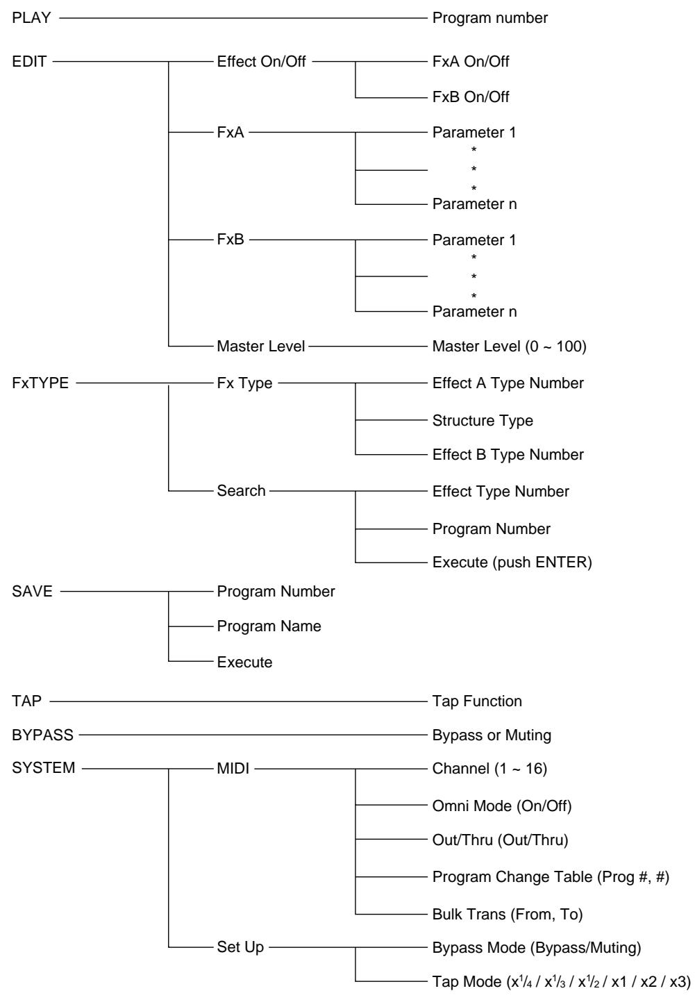
Functional Hierarchy
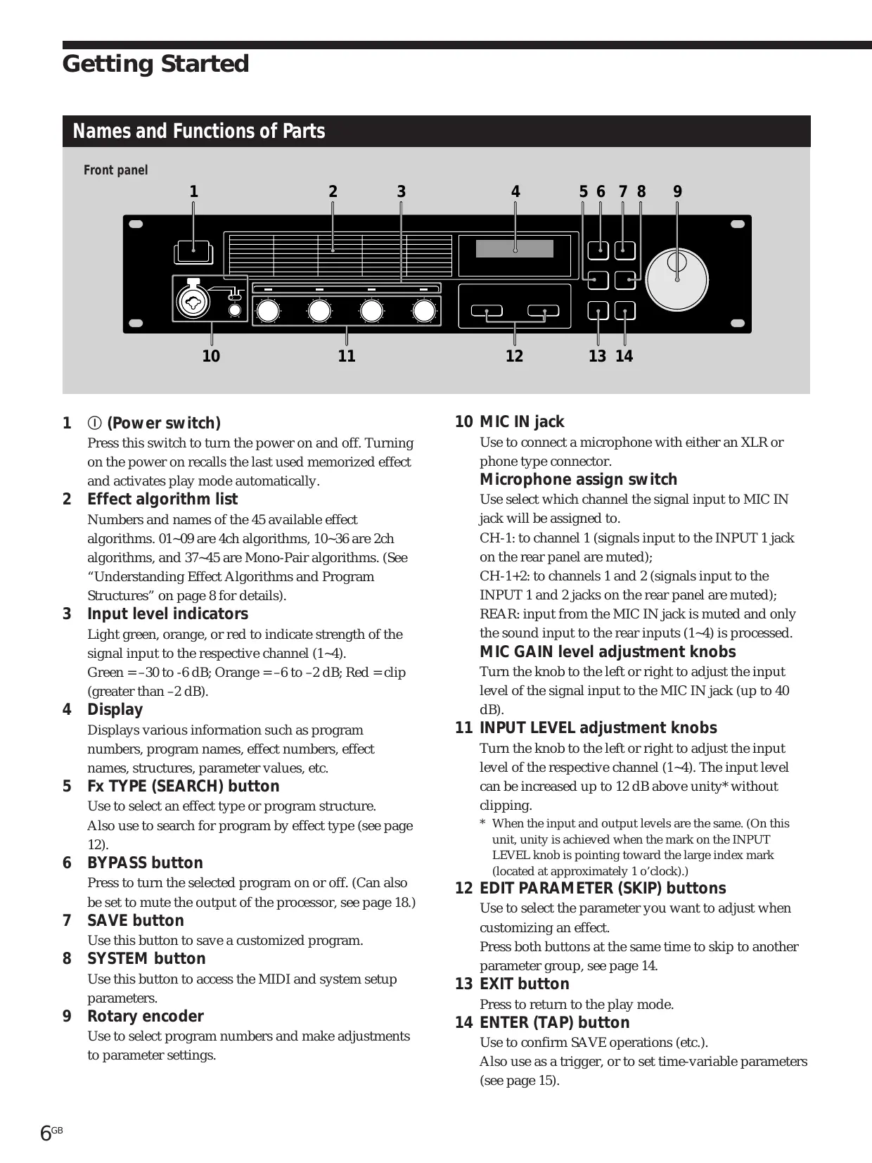
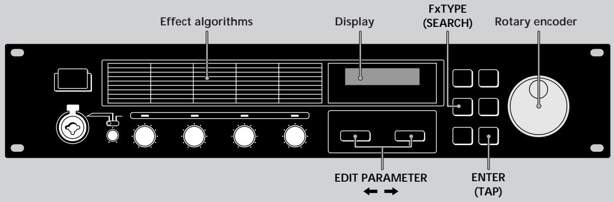
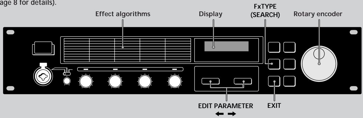
Names and Functions of Parts
Front panel
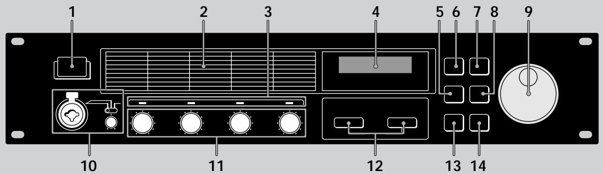
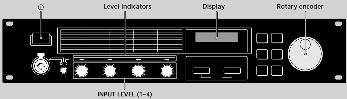
1 ① (Power switch)
Press this switch to turn the power on and off. Turning on the power on recalls the last used memorized effect and activates play mode automatically.
2 Effect algorithm list
Numbers and names of the 45 available effect algorithms. 01 09 are 4ch algorithms, 10 36 are 2ch algorithms, and 37 45 are Mono-Pair algorithms. (See "Understanding Effect Algorithms and Program Structures" on page 8 for details).
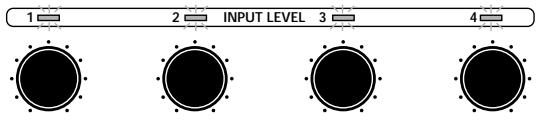
3 Input level indicators
Light green, orange, or red to indicate strength of the signal input to the respective channel (1~4).
Green = -30 to -6dB ; Orange = -6 to -2dB Red = clip (greater than -2dB
4 Display
Displays various information such as program numbers, program names, effect numbers, effect names, structures, parameter values, etc.
5 Fx TYPE (SEARCH) button
Use to select an effect type or program structure.
Also use to search for program by effect type (see page 12).
6 BYPASS button
Press to turn the selected program on or off. (Can also be set to mute the output of the processor, see page 18.)
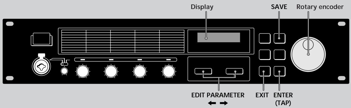
7 SAVE button
Use this button to save a customized program.
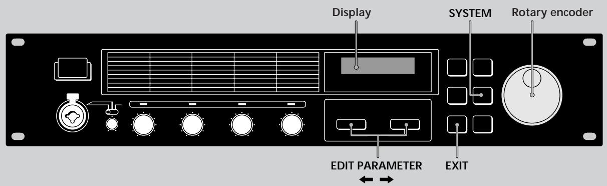
8 SYSTEM button
Use this button to access the MIDI and system setup parameters.
9 Rotary encoder
Use to select program numbers and make adjustments to parameter settings.
10 MIC IN jack
Use to connect a microphone with either an XLR or phone type connector.
Microphone assign switch
Use select which channel the signal input to MIC IN jack will be assigned to.
CH-1: to channel 1 (signals input to the INPUT 1 jack on the rear panel are muted);
CH-1+2: to channels 1 and 2 (signals input to the INPUT 1 and 2 jacks on the rear panel are muted);
REAR: input from the MIC IN jack is muted and only the sound input to the rear inputs (1~4) is processed.
MIC GAIN level adjustment knobs
Turn the knob to the left or right to adjust the input level of the signal input to the MIC IN jack (up to 40 dB).
11 INPUT LEVEL adjustment knobs
Turn the knob to the left or right to adjust the input level of the respective channel (1~4). The input level can be increased up to 12 dB above unity* without clipping.
- When the input and output levels are the same. (On this unit, unity is achieved when the mark on the INPUT LEVEL knob is pointing toward the large index mark (located at approximately 1 o'clock).)
12 EDIT PARAMETER (SKIP) buttons
Use to select the parameter you want to adjust when customizing an effect.
Press both buttons at the same time to skip to another parameter group, see page 14.
13 EXIT button
Press to return to the play mode.
14 ENTER (TAP) button
Use to confirm SAVE operations (etc.).
Also use as a trigger, or to set time-variable parameters (see page 15).
Names and Functions of Parts
Rear panel
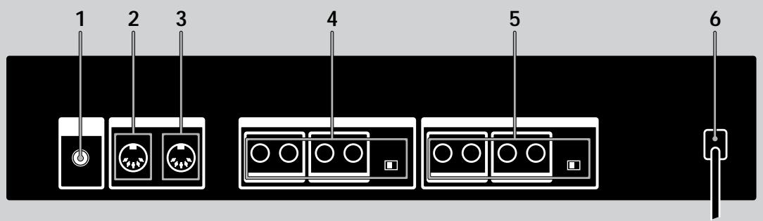
1 LCD CONTRAST knob
Use to adjust the contrast of the display on the front panel.
2 MIDI OUT/THRU terminal
For sending and/or relaying MIDI command signals from the processor to other components. To switch between OUT and THRU, see pages 17~18.
3 MIDI IN terminal
Input for MIDI command signals. Use a commercially available MIDI cable to connect this terminal to another component's MIDI OUT (or THRU) terminal.
4 OUTPUT jacks (1~4)
Standard output jacks for channels 1, 2, 3, and 4.
Connect to and amplifier or mixer (etc.).
Jacks are divided into two groups:
GROUP A (1 (L) and 2 (R))
GROUP B (3 L) and 4 (R)
Output level selector
Use to set the output level of the OUTPUT jacks to match the input level of the connected equipment.
You can select a +4 dBu or -10 dBu output level.
This setting effects all jacks (1, 2, 3, and 4).
5 INPUT jacks (1~4)
Standard input jacks for channels 1, 2, 3, and 4.
Connect to mixer, CD player, or keyboard (etc.).
Jacks are divided into two groups:
GROUP A (1 (L/MONO) and 2 (R))
GROUP B (3 (L/MONO) and 4 (R))
When inputting a monaural signal, use the 1 or 3 (MONO) jacks. The signal is sent to both of the channels in the respective group.
Input level selector
Use to set the input level of the INPUT jacks to match the output level of the connected equipment.
You can select a +4 dBu or -10 dBu input level.
This setting effects all jacks (1, 2, 3, and 4).
6 AC power cord
Connect to an AC power outlet.
Understanding Effect Algorithms and Program Structures
Effect algorithms
This unit contains three types of effect algorithms: 4ch, 2ch, and Mono-Pair.
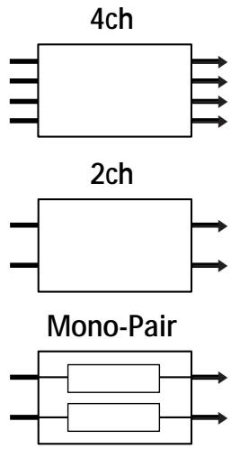
The 4ch effects (algorithms # 01~09) are designed to handle four channels simultaneously. These are also the highest quality effects. Consequently, programs containing these effects can not contain any other effects.
2ch effects (algorithms # 10~36) and Mono-Pair effects (algorithms # 37~45), on the other hand, are designed to handle two channels simultaneously and can be used in various combinations within a program. Each program can contain two 2ch effects, two Mono-pair effects, or one 2ch effect and one Mono-Pair effect.
The 2ch effects are "traditional" stereo effects. Mono-Pair effects are combinations of two parallel mono effects (one for each channel).
Program structures
Each program can contain up two effects (FxA and FxB) depending on the type of effect selected.
If a 2ch or Mono-Pair effects are selected, the program contains two effects (one, or both can be turned off if necessary). When a program contains two effects, the way the unit routes the signals through the effects is controlled by the program structure. There are two possible program structures: parallel (/) and serial () .
Parallel (/) program
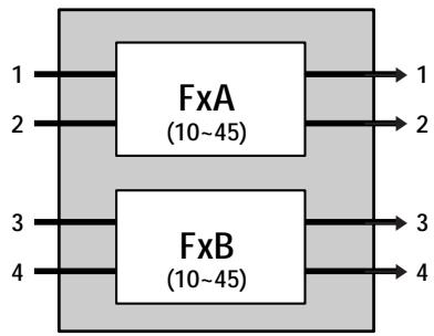
FxA and FxB are completely independent.
Serial () program
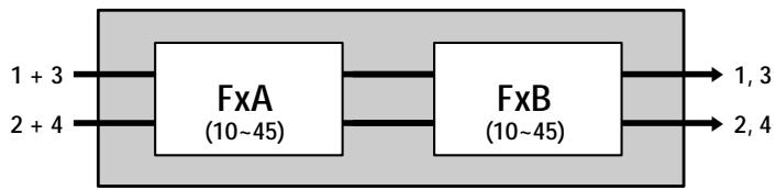
The sound from FxA is fed into FxB for further processing before being output.
If a 4ch effect is selected, the program contains only one effect (the other effect is automatically disabled).
Example of program containing a 4ch effect
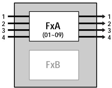
FxA only
Hooking Up
- Before connecting this unit to another device, be sure to unplug the AC power cord from the power outlet.
- Turn off the power switch on this unit and all components to be connected, such as keyboards and active speakers (speakers with built in amplifiers).
- After all the connections, double check that the connections are correct before plugging the AC power cord back into the power outlet.
- If the connected components output large signals that cause distortion, adjust the INPUT LEVEL knobs on this unit to lower the input level, or lower the output level of the connected component.
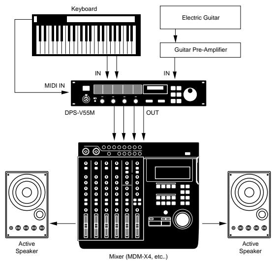
Example 1: Hooking up to instruments
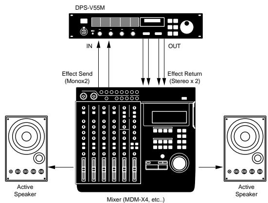
Example 2: Hooking up a mixer (Mono send, Stereo return)
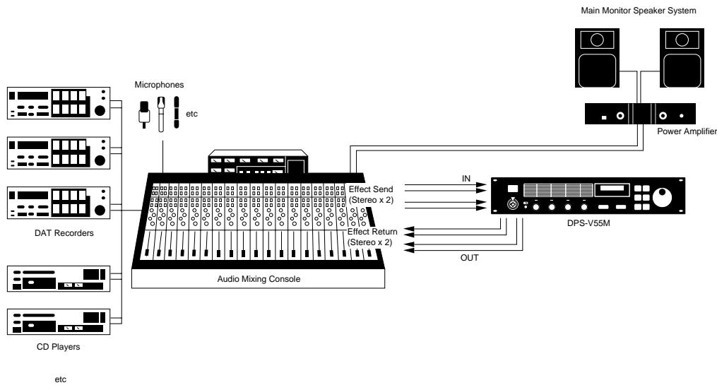
Example 3: Hooking up to a mixer (cutting the direct sound) (Stereo send, Stereo Return)
When using the processor in a send-return loop
- When using effect that have an effect level parameter, we recommend setting the direct sound to "0" so that only the sound of the effect will be output.
- We also recommend setting the BYPASS function to "Muting" (as shown on page 18).
Basic Operations
Choosing a Program
The processor comes with 200 different preset programs (numbers 001 200 ) as well as room for 200 user programs for storing the programs you create (numbers 201 400 ). Use the following procedure to choose the program you desire.
1 Press ① to turn on the power.
After a few seconds, the play mode screen appears.
001 Super Reverb F× A:11 / F× B:12
2 Turn INPUT LEVEL (1~4) to adjust the input levels.
If an input level indicator lights red (clip), the input level for that channel is set too high. Be sure to set the input level correctly since it has a direct relationship to the quality of the effects (see page 6 for details).
3 Turn the rotary encoder to select a program (001~400).
The program numbers (and corresponding names) appear in the display as you turn the jog dial.

Before you turn on the connected components Be sure to turn the volume level down to avoid an unexpected output of massive volume.
You can also search programs by effect type. See page 12 for details.
Reading the Display
During play mode the display provides various information about the selected program
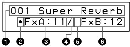
Program number and name:
The number (001~400) and name of the current program.
2 FxA On/Off symbol:
"·": FxA is on (in the illustration, FxA is on).
(Blank): FxA is off
3 FxA effect number:
The number (01~45) of the effect assigned to the current program's FxA block.
The effect numbers correspond to those printed on the front panel to the left of the display. When a 4ch effect is assigned to the FxB block, the FxB effect number and the structure symbol do not appear in the display.
Structure symbol:
“/” (Parallel): To use FxA and FxB separately (the illustration shows a parallel structure).
"→" (Serial) : To feed the output of FxA into FxB for additional processing.
The structure symbols correspond to those printed on the front panel below the display. (See page 8 for details.)
FxB On/Off symbol:
"·": FxB is on
(Blank): FxB is off (in the illustration, FxB is off).
6 FxB effect number:
The number (10~45) of the effect assigned to the current program's FxB block.
The effect numbers correspond to those printed on the front panel to the left of the display.
Outputting Without Effects (BYPASS)
The bypass function allows you to output the original signal without adding any effects. This function can also be set to completely cut (mute) the sound output from the processor (see page 18 if you want to switch to muting).
Press BYPASS to activate the bypass (mute) function.
"BYPASS" (or "MUTING") appears in the display.
Press again to cancel and output with effects.
Selecting Programs by Effect Block
This function lets you search for programs based on the type of effects they contain. In addition to being a good way to explore different implementations of the same effect, it is also a quick way locate a specific program.
1 Press Fx TYPE (SEARCH) twice to display the search screen.
Search:01 Plat1
098 Super Reverb
2 Turn the rotary encoder to select an effect (01~45).
The numbers (01~45) and names of the effects correspond to those printed on the front panel to the left of the display.
Search:03 Room1
017 Sound Fx
The number and name of the first program containing the selected effect appear on the bottom line of the display.
You can also monitor the sound of this program.
3 Press EDIT PARAMETER to move the cursor to the bottom line of the display.
Search:03 Room1
017 Sound Fx
4 Turn the rotary encoder to select a program.
Only programs containing the selected effect (displayed on the first line) will appear. You can also monitor the sound of these programs.
Search:03 Room1
147 Other Program
5 Press ENTER (TAP) to switch to the selected program.
"Executing" appears momentarily and the unit switches to the selected program (and back to play mode).
147 Other Program
-FX:A:03
Editing a Program
Choosing the Effects
Use the following operations to choose the effect(s) to be used in your program. You can choose up to two effect blocks (when using 2ch (10~36) or Mono-Pair (37~45) effects). When using a 4ch effect (01~09), you may choose only one effect. (See page 8 for details).
1 Press Fx TYPE (SEARCH) to display the type screen.
Fx Type:Type
-FxA:11/·FxB:12
2 Turn the rotary encoder to select the effect (01~45) for FxA.
The numbers (01~45) correspond to the effects printed on the front panel to the left of the display.
Fx Type:Type
-FxA:45/·FxB:12
When you select a 4ch effect (numbers 01 09 ), press EXIT to return to play mode and skip the following steps.
3 Press EDIT PARAMETER twice to move the cursor to FxB.
Note: this is not possible if you select a 4ch effect (01~09) in the previous step.
Fx Type:Type
-FxA:45/·FxB:12
4 Turn the rotary encoder to select an effect (10~45) for FxB.
The numbers (10~45) correspond to the effects printed on the front panel.
Fx Type:Type
-FxA:45/·FxB:30
5 Press EXIT to return to play mode.
To change the structure type before returning to the play mode, press EDIT PARAMETER to switch to the structure parameter, then proceed from step 3 of "Choosing the Structure".
Choosing the Structure
This function lets you choose the structure of the effect blocks. Note, this setting is only possible when you have selected effects for both FxA and FxB. (It is not possible when using 4ch effects).
1 Press Fx TYPE to display the effect type screen.
Fx Type:Type
-FxA:11/·FxB:12
2 Press EDIT PARAMETER to display "Struct".
The structure symbol starts blinking.
Fx Type:Struct
- F×A:11/·F×B:12
3 Turn the rotary encoder to select " / " or "→".
The structure symbols correspond to those printed on the front panel below the display.
:/Parallel
Allows you to use FxA and FxB separately.
With this structure, channels 1 and 2 are processed separately from channels 3 and 4.
: Serial
Allows you to feed the output of FxA into FxB for additional processing.
With this structure, channel 1 is mixed with channel 3 and channel 2 is mixed with channel 4.
4 Press EXIT to return to play mode.
Changing the Parameters
Use the following procedures to:
- Turn an effect on or off,
- Adjust individual effect parameters (FxA or FxB)
- Adjust the master volume (output) of the program.
For descriptions of the parameters available for each effect, refer to the separate Effect Parameter Guide.
1 Press EDIT PARAMETER or repeatedly to display the parameter you want to adjust.
2 Turn the rotary encoder to change the parameter.
3 Repeat steps 1 and 2 to change all necessary parameters.
Press EDIT PARAMETER and at the same time to skip to the next parameter group instead of switching parameters one at a time.
The name of the parameter group is shown at the top of the display. The individual parameters and parameter values appear at the bottom.
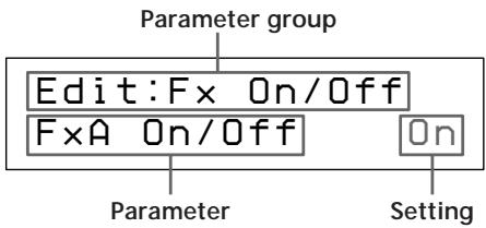
| Parameter group | contains parameters that |
| Fx On/Off | Turn FxA and FxB*1 off or on. |
| FxA [effect name*2] | Change the sound produced by FxA. The number and type of parameters available depends on the effect block.*3 |
| FxB *1 [effect name*2] | Change the sound produced by FxB. The number and type of parameters available depends on the effect block.*3 |
| Master Level | This parameter lets you adjust the output level of the current program. |
1 There are no FxB parameters when FxA is a 4ch effect.
2 The effect name is abbreviated to 5 characters.
*3 Refer to the separate Effect Parameter Guide for detailed information.
4 Press EXIT to return to play mode.
Using the TAP function
This function lets you change the value of certain time related parameters or trigger an effect by tapping on the ENTER (TAP) button.
The parameter which responds to the TAP function is different for each effect, and not all effect have compatible parameters. However, many time related parameters (such as Delay Time) or parameters activated by a trigger (such as Key Trigger) are designed to work with the TAP function. (Refer to the separate Effect Parameter Guide for specific information.)
The TAP function works the same in either play mode or edit mode, but not can not be used when any other modes (such as SYSTEM or SAVE) are active.
To use TAP with time related parameters ("Time" below)
Select a program containing a compatible effect, then tap ENTER (TAP) repeatedly to enter the desired tempo.
The effector's tap editor measures the timing of the last two taps an sets the corresponding parameter accordingly.
You can also change the ratio between your taps and the actual parameter value (see page 18 for details).
To use TAP as a trigger ("Trigger" below)
Press ENTER (TAP) at the point where you want to activate the effect.
Effects that can be adjusted using the TAP function.
| Number | Name | TAP type |
| 7 | Rotary Speaker | Trigger |
| 9 | Doppler | Trigger |
| 15 | Stereo Delay | Time |
| 16 | Ping Pong Delay | Time |
| 22 | Stereo Panner | Trigger |
| 23 | Haas Panner | Trigger |
| 31 | Tremolo | Trigger |
| 32 | Vibrato | Trigger |
| 34 | Pitch Roller | Trigger |
| 36 | Freeze | Trigger |

You can also use MIDI to control the TAP function
Data above 40H received on Control Change 04H produces
the same effect as pressing ENTER (TAP) on the front panel.
Saving your Program
New programs created by changing effect blocks, effect structures, and effect parameters can be stored in memory for later use. You can store up to 200 different user programs using program numbers 201~400.
1 Press SAVE to activate the save mode.
The program number starts blinking.
(A previously saved program name appears in the display.)
Save:
201 Super Reverb
2 Turn the rotary encoder to select the program number (201~400) where you want to save the effect.
(A previously saved program name appears in the display.)
Save:
300 StereoChorus
3 Press EDIT PARAMETER to move the cursor to the program name.
The name of the program you edited appears in the display and the first character starts to blink.
Save:
300 Super Delay
4 Turn the rotary encoder to select a character.
Save:
300 Xuper Delay
5 Use EDIT PARAMETER or to move the cursor into place for the next character.
Repeat steps 4 and 5 to enter up to 12 characters.
6 When you've finished entering the characters, press SAVE (or ENTER (TAP)).
Save:OK?
N[EXIT]/Y[ENTER]
7 The unit will ask for confirmation before saving the program.
To execute the save operation, press ENTER (TAP). If you press ENTER (TAP), "Writing..." appears momentarily, the program is saved, and the unit switches back to the play mode.
If you do not want to save the program, press EXIT. If you press EXIT, the unit returns directly to the play mode without saving the program.
300 X My Program
-FxA:24/·FxB:31
System Operations
The system settings allow you to customize this unit's operating environment. You can specify how the unit will respond to MIDI commands and how the BYPASS and TAP functions will operate.
MIDI Settings
You can use the MIDI interface to control various aspects of this unit. For example, you can switch between memorized effects by using the program table, or save your custom effects to and external storage device.
1 Press SYSTEM.
The first MIDI parameter (MIDI channel) appears automatically.
2 Press EDIT PARAMETER or to choose the MIDI parameter you want to adjust.
The "MIDI Ch" parameter lets you specify the MIDI channel (1~16)
System:MIDI Ch Channel 01
The "MIDI Omni" parameter lets you turn the omni function on or off.
System:MIDI Omni Omni Mode On
The "MIDI Out" parameter lets you specify the function of the MIDI OUT/THRU jack.
System:MIDI Out
Out/Thru Thru
The "MIDI Tabl" parameter lets you create a MIDI program table that specifies which MIDI program change commands will activate which programs.
System:MIDI Tab1
MIDI#001→Prg#001
The "MIDI Bulk" parameter lets you specify the range of MIDI data to be output.
System: MIDI Bulk Trans Sys #400
3 Use the rotary encoder to make the adjustments you desire.
Setting the MIDI channel
1 Use the rotary encoder to specify the MIDI channel (1~16).
2 Press EXIT to return to the play mode or press EDIT PARAMETER or to switch to another parameter.
Setting the MIDI omni operation
1 Use the rotary encoder to select "On" or "Off".
2 Press EXIT to return to the play mode or press EDIT PARAMETER or to switch to another parameter.
1 Use the rotary encoder to select "Thru" or "Out". Thru: Data input to the MIDI IN jack is output as is. Out: Outputs bulk transfer data, etc.
2 Press EXIT to return to the play mode or press EDIT PARAMETER or to switch to another parameter.
System Operations
Setting the MIDI Program Table
1 Use the rotary encoder to specify the MIDI program change number.
System:MIDI Tab1
MIDI#001→Prg#001
2 Press EDIT PARAMETER
3 Use the rotary encoder to specify the program to be switched to.
System:MIDI Tab1
MIDI#006→Prg#006
4 Press EXIT to return to the play mode or press EDIT
PARAMETER or to switch to another parameter.
Setting the MIDI Bulk Transfer Options
1 Make sure the "MIDI Thru/Out" setting is set to "Out".
2 Use the rotary encoder to select "Sys" or the first program number to be transferred.
You can transfer either system settings or program data.
(Sys) : Transfers data for the settings made in the system mode.
(#201~#400): Transfers the program data for the specified range of program numbers.
System:MIDI Bulk Trans #201→#400
3 Press EDIT PARAMETER
4 Use the rotary encoder to select the last program number to be transferred.
System: MIDI Bulk Trans Sys #400
5 Press ENTER (TAP) to output the data.
"Transferring..." appears during the transfer.
When finished, the "MIDI Bulk" parameter reappears.
6 Press EXIT to return to the play mode or press EDIT
PARAMETER or to switch to another parameter.
Other Settings
The system set up parameters let you to select how the BYPASS button and TAP function parameters will operate. For example, you can set BYPASS mute the output of the processor instead of passing the input signal.
1 Press SYSTEM twice.
The first set up parameter ("Bypass") appears automatically.
System: Set UP
BYP Mode Bypass
2 Use the rotary encoder to select "Bypass" or "Muting".
| Select | When |
| Bypass | you want to output the original signal without adding any effects. Only the original signal is output (see “Bypass” on page 11). |
| Muting | you want to completely cut the sound output from the processor (including the input signal). We especially recommend using mute when connecting the processor in a send-return loop with a mixer (as shown on page 9). |
3 Press EDIT PARAMETER to switch to "Tap".
System: Set UP Tap Mode x1
4 Use the rotary encoder to select "x1/4", "x1/3", "x1/2", "x1", "x2", or "x3".
These represent different ratios for calculating the values input via the TAP function.
Example: When the tap is set to "x1/4", tapping at a rate that would normally create a 1 second delay creates a 0.25 second delay.
5 Press EXIT to return to the play mode.
Additional Information
Restoring the Original Factory Settings
You can restore the entire user memory and all system settings to the original factory conditions.
1 Turn off the power.
2 Hold down SAVE and SYSTEM, and turn the power back on. "All Initialize!!" appears in the display and the unit is reset to the original factory settings.
Note
All user memory data is rewritten by the original factory data. Before restoring the original factory settings, be sure to save all necessary data (in a MIDI data filer, etc.).
Replacing the Memory Back-up Battery
If "Battery Low!" appears in the display when you turn on the power, the internal memory back-up battery is nearly exhausted. In order to preserve the user memory data, promptly request battery replacement service from the store of purchase or a nearby Sony dealer.
Note
User memory data may be reverted to the original factory data when requesting battery replacement. Be sure to save important data using an external MIDI data file, or by writing down the settings on a piece of paper (etc.).
Troubleshooting
If this unit does not operate as expected, the problem may simply be an oversight, a disconnected cable or a setting error. Before calling a service technician, compare the symptoms of the problem with those listed below to see if you can correct the problem yourself.
No sound is heard, or the sound is small.
Press BYPASS to cancel mute.
Check to see if the INPUT LEVEL knobs are set to the appropriate level.
Check that all the cables are connected correctly.
Make sure the level of the "Master Level" parameter is not set excessively low (see page 14).
Check the volume of the connected amplifier or mixer.
The input sound is not modified.
Press BYPASS to cancel bypass.
Is one (or both) of the effects set to "Off"?
The input level indicator lights red.
Turn INPUT LEVEL to the left to reduce the input level of the respective channel.
Reduce the output level of the source component.
Set the INPUT level selector switch to +4 dB and use the INPUT adjustment knob to re-adjust the input level.
MIDI operations cannot be carried out.
Make sure the MIDI receive channel matches the transmit channel of the MIDI device.
Make sure the MIDI cable is connected securely.
Make sure the MIDI program table is set correctly.
"RAM Error!" appears in the display and output is cut off.
Reset the unit using the procedure described in "Restoring the Original Factory Settings".
Additional Information
Precautions
On safety
- Should any liquid or solid object fall into the unit, unplug the unit and have the unit checked by qualified personnel before operating it any further.
On power sources
- Before operating the unit, be sure that the operating voltage of your unit is identical with that of your local power supply.
- Unplug the unit from the wall outlet if it is not to be used for an extended period of time. To disconnect the cord, pull it out by grasping the plug. Never pull the cord itself.
- AC power cord must be changed only at the qualified service shop.
On placement
- Place the unit in a location with adequate ventilation to prevent heat build-up and prolong the life of its components.
- Do not place the unit near heat sources, or in a place subject to direct sunlight, excessive dust or mechanical shock.
- Do not place anything on top of the cabinet which might block the ventilation holes and cause malfunctions.
On cleaning the cabinet
- Clean the cabinet, panels and controls with a soft cloth lightly moistened with a mild detergent solution. Do not use any type of abrasive pad, scouring powder or solvent such as alcohol or benzine.
On repacking
- Do not throw away the carton and the packing material. This makes an ideal container when transporting the unit. When shipping the unit, repack it as it was packed at the factory.
If you have any question or problem concerning your unit that is not covered in this manual, please consult your nearest Sony dealer.
When requesting repairs, all user program data (#201~400) will be reverted to the original factory data settings. Before requesting repairs, be sure to save your important data using an external MIDI data filer, or by making written notes of the parameter settings.
Specifications
A/D Converter 20 bit resolution
D/A Converter 20 bit resolution
Sampling
Frequency 48 kHz
Input (rear panel)
| Jack type | reference input level | maximum input level | input impedance | circuit type |
| PHONE | -10 dBu or +4 dBu | +20 dBu | More than 45 kilohms | unbalanced |
Input (front panel)
| Jack type | reference input level | maximum input level | input impedance | circuit type |
| XLR/PHONE | -50 dBu | +10 dBu | 10 kilohms | balanced |
Output
| Jack type | reference output level | maximum output level | load impedance | circuit type |
| PHONE | -10 dBu or +4 dBu | +10 dBu or +20 dBu | less than 1 kilohm | unbalanced |
MIDI Input/Output Jack: 5 pin DIN (IN x 1, OUT/THRU x 1) OUT/THRU can be set to either OUT or THRU
Frequency Response 20Hz 22kHz(+0, - 1dB)
Signal-to-Noise
Ratio Greater than 93 dB
Distortion Less then 0.005% (1 kHz)
Effect Algorithms 45 (4ch: 9, 2ch: 27, Mono-Pair: 9)
Memory Preset 200 locations (numbers 001~200) User 200 locations (numbers 201~400)
Power Source AC 230 V, 50/60 Hz
Power Consumption 12 W (230 V)
Dimensions 482 x 88 x 290 mm (WxHxD not including projections)
Mass approx. 3.6kg
Supplied accessories Operating Instructions (1) Effect Parameter Guide (1) Preset Memory Catalog (1)
Design and specifications subject to change without notice.
AVERTISSEMENT
Structure de programme parallele (I)
12 EDIT PARAMETER (SKIP)-Tasten

- Multi-Effect Processor
- Table of Contents
- Getting Started
- Basic Operations
- Editing a Program
- System Operations
- Additional Information
- Main Features
- Four channel construction
- Flexible effect algorithms and program structures
- User-friendly operating environment
- Large memory banks
- Search function
- TAP function
- MIDI compatibility
- How to Use This Manual
- Functional Hierarchy
- Names and Functions of Parts
- ① (Power switch)
- Effect algorithm list
- Input level indicators
- Display
- Fx TYPE (SEARCH) button
- BYPASS button
- SAVE button
- SYSTEM button
- Rotary encoder
- MIC IN jack
- Microphone assign switch
- MIC GAIN level adjustment knobs
- INPUT LEVEL adjustment knobs
- EDIT PARAMETER (SKIP) buttons
- EXIT button
- ENTER (TAP) button
- LCD CONTRAST knob
- MIDI OUT/THRU terminal
- MIDI IN terminal
- OUTPUT jacks (1~4)
- Output level selector
- INPUT jacks (1~4)
- Input level selector
- AC power cord
- Understanding Effect Algorithms and Program Structures
- Effect algorithms
- Program structures
- Hooking Up
- When using the processor in a send-return loop
- Choosing a Program
- Press ① to turn on the power.
- Turn INPUT LEVEL (1~4) to adjust the input levels.
- Turn the rotary encoder to select a program (001~400).
- Reading the Display
- Outputting Without Effects (BYPASS)
- Press BYPASS to activate the bypass (mute) function.
- Selecting Programs by Effect Block
- Choosing the Effects
- Choosing the Structure
- Changing the Parameters
- Using the TAP function
- To use TAP with time related parameters ("Time" below)
- To use TAP as a trigger ("Trigger" below)
- Saving your Program
- Press SAVE to activate the save mode.
- Turn the rotary encoder to select the program number (201~400) where you want to save the effect.
- Press EDIT PARAMETER → to move the cursor to the program name.
- Turn the rotary encoder to select a character.
- Use EDIT PARAMETER ← or → to move the cursor into place for the next character.
- When you've finished entering the characters, press SAVE (or ENTER (TAP)).
- The unit will ask for confirmation before saving the program.
- MIDI Settings
- Press SYSTEM.
- Press EDIT PARAMETER ← or → to choose the MIDI parameter you want to adjust.
- Use the rotary encoder to make the adjustments you desire.
- Setting the MIDI channel
- Setting the MIDI omni operation
- Setting the MIDI Program Table
- Setting the MIDI Bulk Transfer Options
- Other Settings
- Press SYSTEM twice.
- Use the rotary encoder to select "Bypass" or "Muting".
- Press EDIT PARAMETER → to switch to "Tap".
- Use the rotary encoder to select "x1/4", "x1/3", "x1/2", "x1", "x2", or "x3".
- Press EXIT to return to the play mode.
- Restoring the Original Factory Settings
- Note
- Replacing the Memory Back-up Battery
- Troubleshooting
- Precautions
- On safety
- On power sources
- On placement
- On cleaning the cabinet
- On repacking
- Specifications
- AVERTISSEMENT
- EDIT PARAMETER (SKIP)-Tasten
Brand : SONY
Model : DPS-V55M
Category : Audio System