
SRX-R515P - Audio System SONY - Free user manual and instructions
Find the device manual for free SRX-R515P SONY in PDF.


| Product Type | Digital Cinema Dual System (SRX-R515P) comprising SRX-R515 projector, XCT-S10 server, LKRA-007 touch panel monitor, LKRA-010 dual system accessory kit, LKRA-011 3D filter and holder, and LKRA-PCAB1 projector auto calibration box. |
| Projection System | 3-chip 1.48-inch 4K SXRD, resolution 4096 x 2160 pixels |
| Light Source | 450 W or 330 W high-voltage mercury (HPM) lamp (6 lamps) |
| Light Output | 15,000 lumens (center) with 450 W lamp |
| Contrast Ratio | 8,000:1 (average) |
| Supported Playback Formats | JPEG 2000: 4K 2D 24p, 2K 2D 24p/25p/29.97p/30p/48p/60p, 2K 3D 24p/29.97p/30p/48p/60p; MPEG-2 MP@HL up to 80 Mbps |
| Video Inputs | HDMI (2) |
| Audio Outputs | Unbalanced 8ch 24-bit 48/96 kHz PCM (D-sub 25-pin), AES/EBU 16ch 24-bit 48/96 kHz PCM (D-sub 25-pin) |
| Projector Dimensions (W x H x D) | 548 x 634 x 1119 mm (21.6 x 25.0 x 44.1 in) including lens shift block and feet |
| Projector Weight | Approx. 145 kg (319 lb) excluding touch panel monitor and lamp |
| Projector Power Requirements | 200-240 V AC, 50/60 Hz, 21.5-18 A |
| Server Model | XCT-S10 Digital Cinema Server |
| Server Storage | 4 TB HDD (expandable to 8 TB), Modified RAID 6 |
| Server Dimensions (W x H x D) | 482 x 131 x 560 mm (19.0 x 5.2 x 22.0 in) |
| Server Weight | Approx. 24 kg (52.9 lb) (Serial No. xx0xxxx) or 19 kg (41.9 lb) (Serial No. xx1xxxx) |
| Server Power Requirements | 100-240 V AC, 50/60 Hz, 2.2-1.0 A |
| Touch Panel Monitor | 15-inch XGA (1024 x 768), LKRA-007 |
| Calibration Box Model | LKRA-PCAB1 Projector Auto Calibration Box |
| Operating Temperature | 5°C to 35°C (41°F to 95°F) (projector and server) |
| Operating Humidity | 35% to 85% (non-condensing) (projector and server) |
| Maintenance | Lamp replacement, air filter cleaning, periodic calibration via SPL or manual |
| Safety | Refer to supplied Safety Regulations; includes emergency switch, cooling fan interlocks |
| Spare Parts / Repairability | Lamp (450W or 330W), air filters, lens (separate), connection cables; service by qualified Sony personnel |
| General Information | Dual system for 2D/3D projection; includes DCP/KDM ingestion, SPL scheduling, auto calibration |
Frequently Asked Questions - SRX-R515P SONY
User questions about SRX-R515P SONY
0 question about this device. Answer the ones you know or ask your own.
Ask a new question about this device
Download the instructions for your Audio System in PDF format for free! Find your manual SRX-R515P - SONY and take your electronic device back in hand. On this page are published all the documents necessary for the use of your device. SRX-R515P by SONY.
USER MANUAL SRX-R515P SONY
Digital Cinema Dual System
Operating Instructions
Before operating the unit, please read this manual and supplied Safety Regulations thoroughly and retain it for future reference.
SRX-R515P
SRX-R515
LKRA-010
LKRA-011
LKRA-PCAB1
HDMI
Table of Contents
Please Read This First 3
Notations Used in This Guide .... 3
Manual Structure 3
About License 3
USB HDD and USB Memory Devices That can be Used on INGEST PORT 1/2 of This Unit ...... 3
Recognized Folder Names 3
On Security 3
Overview
System Configuration Example 4
Part Names and Functions .... 5
SRX-R515 Digital Cinema Projector 5
XCT-S10 Digital Cinema Server 8
LKRA-007 Touch Panel Monitor 10
LKRA-011 3D filter and holder .... 11
LKRA-PCAB1 Projector Auto Calibration Box 12
Main Screen 13
Items to Check
Startup 15
Turning on the Main Power on the Projectors ..... 15
Starting up the Server 15
Logging Into the System 15
Starting the Projectors 16
Rebooting the System 17
Shutting Down the System 17
Operations
Sequence of Operations 18
Selecting the Projector to be Controlled 18
Ingesting DCP 19
Ingesting from HDD via USB Connector ..... 19
Ingesting from HDD via CRU DATAPORT ..... 20
Ingesting via Network 21
Ingesting KDM 21
Ingesting from a USB Flash Drive 21
Ingesting from a Network Folder 22
Playing Back CPL 23
Calling up Screen Adjustment Data 23
Selecting a CPL 24
Playing Back CPL 25
Creating an SPL 26
Creating an SPL 26
Setting an Intermission in the SPL 28
Triggering SPL Playback Using GPI Signals ..... 29
Playing Back an SPL 30
Selecting an SPL 30
Playing Back an SPL 30
Creating a Schedule 30
Creating a Schedule 30
Importing/Exporting Schedules 31
Projecting Images Using an External Playback
Device 32
Manually Controlling Theater Facilities .... 33
Others
Opening/Closing the 3D Filter 34
Opening the 3D Filter 34
Closing the 3D Filter 34
Calibrating the Screen 35
Installing the Calibration Camera 35
LCD Panel Displays 37
Preparation 37
Performing Calibration 38
Periodic Calibration Using SPLs 40
Attaching and Removing the Lens 42
Removing the Lens 42
Attaching the Lens 43
How to Read the Indicators 44
Troubleshooting 46
Error Code List (LKRA-PCAB1) 48
Specifications 50
SRX-R515 Digital Cinema Projector 50
XCT-S10 Digital Cinema Server 50
LKRA-007 Touch Panel Monitor 51
LKRA-010 Dual System Accessory Kit 51
LKRA-011 3D filter and holder .... 51
LKRA-PCAB1 Projector Auto Calibration Box 51
Trademarks
- The terms HDMI and HDMI High-Definition Multimedia Interface, and the HDMI Logo are trademarks or registered trademarks of HDMI Licensing LLC in the United States and other countries.
- Other products or system names appearing in this document are trademarks or registered trademarks of their respective owners.
Further, the ® or ™ symbols are not used in the text.
- Reproduction or duplication, in whole or part, of the operation manual supplied with the system without the authorization of the right holder is prohibited under copyright law.
- Sony assumes no responsibility for damages, loss of income, or any claims from a third party arising out of use of the system.
- Note that the specifications of the system are subject to change for improvement without prior notice.
Please Read This First
Notations Used in This Guide
In this guide, the SRX-R515 Digital Cinema Projector is referred to as the “projector,” the XCT-S10 Digital Cinema Server is referred to as the “server,” the LKRA-007 Touch Panel Monitor is referred to as the “touch panel monitor,” and the system consisting of the above is referred to as the “SRX-R515P.”
Manual Structure
The following manuals are provided for the digital cinema dual system depending on the application.
Safety Regulations (SRX-R515P)
This includes safety instructions and precautions for using the SRX-R515P.
Before Using This Unit (SRX-R515, LKRA-010, LKRA-011, LKRA-PCAB1)
This includes safety instructions, precautions and specifications for using the unit.
Installation Manual
This includes instructions on how to install the unit, information on default settings, and instructions on how to adjust the system. Be sure to refer to this manual whenever you need to change settings or readjust the unit after installation.
Operating Instructions (this guide)
This includes instructions for screening controls in a theater, how to create a screening schedule, how to change lenses, projector part names, and product specifications. Be sure to refer to this guide for instructions on daily usage.
Maintenance Manual
This includes information such as instructions on periodic inspection, maintenance, and cleaning.
Service Manual
This is intended for use by service personnel and includes information on diagnosing malfunctions and instructions on repair.
About License
Refer to "Software License Agreement."
USB HDD and USB Memory Devices That can be Used on INGEST PORT 1/2 of This Unit
USB HDD and USB memory devices that can be used on INGEST PORT 1/2 of this unit are as follows.
- USB 2.0/3.0 (bus power capacity up to 1 A)
- Do not insert a bus-powered USB HDD and a USB memory device into the two ports at the same time.
- USB HDD compatible file system ext2, ext3
(Operation is not guaranteed for all types of USB HDD and USB memory devices.)
Recognized Folder Names
Regarding the external directories (USB HDD, USB memory devices, network folders, etc.) that are connected to the unit, only folder names that consist of alphanumeric characters will be recognized by the unit.
On Security
- SONY WILL NOT BE LIABLE FOR DAMAGES OF ANY KIND RESULTING FROM A FAILURE TO IMPLEMENT PROPER SECURITY MEASURES ON TRANSMISSION DEVICES, UNAVOIDABLE DATA LEAKS RESULTING FROM TRANSMISSION SPECIFICATIONS, OR SECURITY PROBLEMS OF ANY KIND.
- Depending on the operating environment, unauthorized third parties on the network may be able to access the system.
We strongly recommend configuring all of the passwords for security purposes.
For details on configuring all the passwords, refer to the Installation Manual. - Do not browse any other website in the Web browser while making settings or after making settings. Since the login status remains in the Web browser, close the Web browser when you complete the settings to prevent unauthorized third parties from using the unit or harmful programs from running.
System Configuration Example
The digital cinema dual system consists of the following products.
• SRX-R515P Digital Cinema Projector Package
– SRX-R515 Digital Cinema Projector (main projector)
- XCT-S10 Digital Cinema Server
- LKRA-007 Touch Panel Monitor
• SRX-R515 Digital Cinema Projector (sub projector)
• LKRA-010 Dual System Accessory Kit: base and conduit kit
• LKRA-011 3D filter and holder: 3D projection kit
• LKRA-PCAB1 Projector Auto Calibration Box: camera for automatically calibrating convergence

flowchart
graph TD
    A["Network hub"] --> B["XCT-S10"]
    B --> C["UPS"]
    C --> D["Tripod"]
    D --> E["LKRA-PCAB1"]
    E --> F["LKRA-010"]
    F --> G["Sub projector"]
    G --> H["LKRA-010"]
    H --> I["Main projector"]
    I --> J["LKRA-007"]
    J --> K["To sub projector"]
    K --> L["LKRA-010"]
    L --> M["LKRA-011"]
    M --> N["To main projector"]
Part Names and Functions
SRX-R515 Digital Cinema Projector
Front

①8-inch duct attachment part
Used to attach an 8-inch exhaust duct.
② Lens fixing lever
Locks/unlocks the lens.
For further details, see “Attaching and Removing the Lens” (page 42).
③ Lens attachment part
Used to attach a separately-sold lens.
For further details, see “Attaching and Removing the Lens” (page 42).
Rear
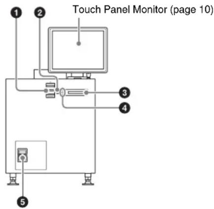
①Status lights
Shows the status of the projector.
For further details, see “How to Read the Indicators” (page 44).
②EMERGENCY switch
Forcibly shuts off the lamp (equipped with a cooling function).
③STATUS MESSAGE window
Displays various messages.
④Status indicators
Shows the status of the projector.
For further details, see "How to Read the Indicators" (page 44).
⑤Power switch
Turns the projector's main power on (1) or off (O).
When turning the power off
Wait for the lamp's cooling process to complete before turning the power switch off.
For further details, see "Shutting Down the System" (page 17).
Left side

① Lamp access panel (lamp grill)/ventilation holes (intake)/air filter
A lamp access panel (lamp grill), ventilation holes (intake), and air filter are also located on the right side of the unit.
For details on lamp replacement, refer to the "Maintenance Manual."
For details on air filter cleaning, refer to the "Maintenance Manual."
②Ventilation holes (intake)/air filter
For details on air filter cleaning, refer to the "Maintenance Manual."
Connector block: Main projector

Connector block: Sub projector

①NETWORK connector (RJ-45 modular jack)
Used to connect to the server's PRJ connector with the supplied LAN cable.
②INTER LOCK connector (D-sub 15 pin, female)
This is not used in this system.
③RS-232C connector (D-sub 9 pin, female)
Used to connect to a LKRA-PCAB1.
Main projector: Use the supplied connection cable to connect the CTRL2 connector on the LKRA-PCAB1.
Sub projector: Use the supplied connection cable to connect the CTRL1 connector on the LKRA-PCAB1.
4 AUDIO OUTPUT BAL/UNBAL (audio output BAL/UNBAL) (AES/EBU) connector (D-sub 25 pin, female)
For connecting to an audio signal processor.
⑤STATUS 1/2 (Status 1/2) indicator
Shows the status of the projector.
For further details, see "How to Read the Indicators" (page 44).
⑥ SERVER connector
Used to connect to the server with the supplied PCI express cable (2 m).
⑦RS-232C connector
This is not used in this system.
⑧Link B OUT connector
Connect this connector on the main projector to the Link B IN connector on the sub projector.
This connector is not used on the sub projector.
⑨Link B IN connector
Connect this connector on the sub projector to the Link B OUT connector on the main projector. This connector is not used on the main projector.
⑩Link A OUT connector
Connect this connector on the main projector to the Link A IN connector on the sub projector.
This connector is not used on the sub projector.
⑪Link A IN connector
Connect this connector on the sub projector to the Link A OUT connector on the main projector.
This connector is not used on the main projector.
⑫HDMI IN 1/2 (HDMI input 1/2) connector
For HDMI signal input.
For details on signal format, see "HDMI signals" (page 52).
XCT-S10 Digital Cinema Server
Front

① POWER indicator
Shows the status of the server's power.
For further details, see "How to Read the Indicators" (page 44).
② SYSTEM SW switch
Starts up the server.
③ (IFDD) 1/2 indicator
Shows the status of the HDD.
For further details, see "How to Read the Indicators" (page 44).
④ Ventilation holes (intake)/air filter
For details on air filter cleaning, refer to the "Maintenance Manual."
⑤INGEST PORT 1/2 connector
For inserting HDD or USB memory to ingest DCP/KDM.
These can only be used for a USB HDD or USB memory device.
For systems on which periodic calibration using SPLs is performed, connect the calibration camera to the INGEST PORT 1 connector.
For further details, see "Ingesting from HDD via USB Connector" (page 19), and "Ingesting from a USB Flash Drive" (page 21).
⑥CRU DATAPORT
For inserting HDD to ingest DCP/KDM.
A CRU DATAPORT carrier is necessary to use the CRU DATAPORT. For further details, contact qualified Sony service personnel.
Rear
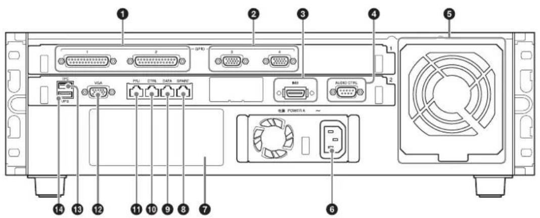
①GPIO 1/2 connector (D-sub 25 pin, female) For connecting to an external device.
For further details, refer to the “Installation Manual.”
② GPIO 3/4 connector (D-sub 15 pin, female) For connecting to an external device.
For further details, refer to the “Installation Manual.”
③IMB connector Used to connect to the projector with the supplied PCI express cable.
4 AUDIO CTRL connector (D-sub 9 pin, male) Used to control audio devices.
⑤Fan Unit An exhaust fan.
⑥Power unit ( ) Connects with the power cord.
⑦Power unit B mount For use with separately-sold expansion power units. With both power units A and B attached, each can be used as a redundant power source. To connect a power unit, contact qualified Sony service personnel.
⑧ SPARE connector (RJ-45 modular jack) For future expansions.
⑨DATA connector (RJ-45 modular jack) Used to connect to a theater network (LAN) and allow linking and data transfer with other systems. Be sure to use a CAT6 or above for the LAN cable.
⑩CTRL connector (RJ-45 modular jack) Used to connect to a theater network (LAN) and allow linking and data transfer with other systems. Be sure to use a CAT6 or above for the LAN cable.
11PRJ connector (RJ-45 modular jack) Used to connect to the projector's NETWORK connector with the supplied LAN cable.
⑫VGA connector (D-sub 15 pin, female) Used to connect to the touch panel monitor's VGA connector with the supplied VGA cable.
For connection instructions, refer to the “Installation Manual.”
13 TPC connector Used to connect to the touch panel monitor's TPC connector with the supplied USB cable.
For connection instructions, refer to the “Installation Manual.”
14 UPS connector Used to connect to an uninterruptible power supply (UPS).
LKRA-007 Touch Panel Monitor
Right side

①MENU switch
Displays the menu.
② ▲ / ▼ switches
Used for moving the menu and setting new values.
③SELECT switch
Used for selecting the menu and items.
④ (Power) switch
Press this to turn the power on.
Press this again to turn the power off.
Caution
- When turning the power on, do not touch the touch panel monitor screen. Doing so may prevent normal operations after start-up.
- When the power is on, do not remove the touch panel monitor cable.
⑤Monitor stand
This is equipped with a tilt mechanism.
The monitor's position can be adjusted in the up, down, left, and right directions.
Bottom

① VGA connector (D-sub 15 pin, female)
Used to connect to the server's VGA connector with the supplied VGA cable.
For connection instructions, refer to the "Installation Manual."
②RS-232C connector (D-sub 9 pin, female)
For service use.
③TPC connector
Used to connect to the server's TPC connector with the supplied USB cable.
④Power input connector
For connecting the supplied AC adapter.
For connection instructions, refer to the "Installation Manual."
LKRA-011 3D filter and holder
(The 3D filters are installed to open to the left and right in the following sample illustration.)

①Lock pin
Locks the 3D filter holder.
②3D filter holder
Holds the 3D filter.
③3D filter
For details on using the 3D filter, see "Opening/Closing the 3D Filter" (page 34).
LKRA-PCAB1 Projector Auto Calibration Box
For details on how to use the LKRA-PCAB1, see "Calibrating the Screen" (page 35).


①Indicator B
Indicates the system status of the LKRA-PCAB1.
②Indicator A
Indicates that the hardware is initializing.
③ Calibration camera
Measures the convergence of the two projectors.
④Tripod hole
⑤LCD panel
For details on the display screen, see "LCD Panel Displays" (page 37).
⑥ Touch sensor
Operate the LKRA-PCAB1 application by touching the "buttons" that correspond with the functions that appear in the function area of the LCD panel. Only the LEDs that correspond to a currently controllable function will light.
Touching the sensor with a pen or your fingernails may result in erroneous operation. Be sure to touch the sensor firmly with your fingertips.

⑦Projector status LED
Indicates the connection status between the LKRA-PCAB1 and the projectors.
⑧ GND connector
Connects to safety grounding.
⑨CTRL1 connector
Use the supplied connection cable to connect this to the RS-232C connector on the sub projector.
⑩COM connector
This is currently not used. (Intended for future expansion.)
⑪Power status LED
Indicates the power status.
⑫DC IN connector
Connect the DC power cable of the supplied AC adapter here.
⑬CTRL2 connector
Use the supplied connection cable to connect this to the RS-232C connector on the main projector.
Main Screen

① Auditorium number
If a computer is being used to control multiple auditoriums via a network, the auditorium numbers will be displayed. Touch the number to display the auditorium selection dialog box, and then select the auditorium to operate.
Caution
Multiple auditoriums can only be controlled via a network when a browser is used on a computer to operate this unit. Do not control multiple auditoriums using the touch panel monitor.
②Date display
Displays the current date (server date).
③Next SPL title for screening
④SPL playback status
Displays the SPL playback status using the same icons used for the playback control buttons.
For details on the buttons, see "Playing Back CPL" (page 25).
⑤ Current SPL title
6Progress bar
Displays the progress of the title currently being screened by CPL or SPL frames.
⑦ Elapsed showing time
Displays an approximate time. Although there may be a slight discrepancy in the units depending on system conditions, this will not affect the actual screening.
⑧Scheduled start time of next SPL for screening / time remaining until start
⑨Projector status indicator / control button
Indicates the operation status of the projector. When you tap the button, the "Projector Lamp Control" dialog box appears allowing you to operate the projector.
⑩Job display button
Tap the button to switch to the "Job Status" screen in the [Library] tab.
⑪ Error display button
Displays the status of the device being controlled by the server.
When you tap the button, the “Error History” screen appears.
For details on the “Error History” screen, refer to the “Maintenance Manual.”
Error: An error has occurred. (screening stops)
Warning: A non-fatal problem or error has occurred. (screening continues)
Normal: The status is normal.
⑫Login user name
Displays the login user name.
13 (Power) button
This enables shutdown, or logout from the projection system. (page 17)
14 Main menu
This menu provides access to all the functions on this unit. The following menus are also available.
[Status]: Monitors the title being screened. Manual playback can also be performed here.
For details on how to read the status, see “To check installation/connections” (page 46).
[Schedule]: Creates a schedule.
See "Creating a Schedule" (page 30).
[SPL]: Creates an SPL (Show Playlist).
See "Creating an SPL" (page 26).
[Library]: Manages DCP (Digital Cinema Package) or KDM (Key Delivery Message).
See “Ingesting DCP” (page 19), and “Ingesting KDM” (page 21).
[Configuration]: Adjusts various settings.
For details on indicators, refer to the "Installation Manual."
⑮Projector selection button
Selects the projector (main or sub) to be controlled.
For details, see "Selecting the Projector to be
Controlled" (page 18).
16Playback mode display button
Displays the playback mode.
Tap the button to switch the playback mode.
Manual: Playback is performed manually.
Scheduled: Playback is performed using a schedule. You can select the [Play Manually] checkbox to perform playback manually even in schedule mode.
⑰Version information
Displays the version information of the projector.
⑱Projector information display
Displays information about the projector.
See “Calling up Screen Adjustment Data” (page 23), “Manually Controlling Theater Facilities” (page 33).
19Shortcut button
Often-used functions are registered to this button.
Tap the button to activate a function.
Note
The following operations can be carried out in [Prepare].
- Turn the lamp on
- Open the douser
- Cancel muting
- Cancel test pattern display
To register a function to the shortcut button, refer to the "Installation Manual."
20Error information display
Displays the location and time an error occurred, an explanation of the error and a solution.
When an error occurs, refer to [Solution] on the lower left to deal with the problem.
When multiple errors or warnings have occurred, you can check the next or previous warning by tapping [>] or [<].

The solution will be displayed here. Follow the instructions to deal with the problem.
②Playback control button
In manual playback mode, you can control playback.
For details, see "Playing Back CPL" (page 25).
Items to Check
Startup
When starting up the projection system, turn on the projectors' main power first, and then start up the server and log in to the system.
Turning on the Main Power on the Projectors
Lower the power switch at the rear of each projector to the on position (l) to turn on both projectors.

natural_image
Simple line drawing of a box with internal compartments and an upward arrow (no text or symbols)The power will turn on and the MAIN indicator and LAMP indicator will turn solid red when the projectors enter standby mode.
Starting up the Server
Press the SYSTEM SW switch on the server's front to turn it on.

The POWER indicator will blink green, and after start-up is complete, it will turn solid green.
Once the server is on, the "Login" screen will be displayed on the monitor.
Caution
- Do not start up the server with a USB device inserted in INGEST PORT1/2 connector on the front of the server. The USB device may not be recognized.
- When starting-up the server, do not touch the touch panel monitor screen. Doing so may prevent normal operations of the touch panel monitor after start-up.
Logging Into the System
Caution
It is necessary to pre-register as a user to log in to the projection system.
For further details, refer to the "Installation Manual."
1 Tap your own user name in the user list, and then tap the [Password] column.

A virtual keyboard for entering your password will be displayed.
2 Enter your password, and then tap [Enter].
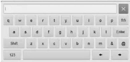
If you make a mistake when entering your password, tap [BS] to delete the last character.
When the password is entered, it will be displayed masked above the keyboard.
Notes
- Startup of the projection system will take some time. Startup processes for the server continue even after the user list appears. Lists, such as those for ingested CPLs, will not appear until the startup processing is complete.
- You can change your password.
See "To change your login password" (page 16).
The virtual keyboard will disappear, and asterisks (*) will be entered in the [Password] column.
3 Tap [Login].
Once you log in to the system, the "Status" screen will be displayed.

Proceed to "Starting the Projectors" (page 16).
To change your login password
As a user, you can change your own password.
1 Tap the area where the user name is displayed at the top right of the screen to display the "Login" screen, and tap [Change Password].
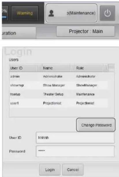
A screen for changing your password will be displayed.
2 Enter the old password and new password, and then tap [OK].
Tap each field to display a virtual keyboard, and enter the necessary information.
3 Tap [OK] when the confirmation screen appears.

Your password will be changed.
Changing the login user
1 Tap on the upper right of the screen.
2 Select [Logout], and then tap [OK].

3 Tap [OK] when the confirmation screen appears.

The "Login" screen will be displayed.
4 Change the user and log in.
Starting the Projectors
1 In the "Status" screen, tap [Standby].

The "Projector Lamp Control" dialog box will be displayed.
2 Tap [Power ON].

The MAIN indicators on the rear of the projectors will turn solid green, and the LAMP indicators will blink green.
When the main projector turns on, its MAIN, LAMP, and IMB indicators will be solid green.
When the sub projector turns on, its MAIN and LAMP indicators will be solid green (its IMB indicator will remain red).
3 Tap [Close] to close the "Projector Lamp Control" dialog box.
The above procedures complete preparations and confirmation for using the projection system.
Rebooting the System
1 Tap on the upper right of the screen.
2 Select [Reboot], and then tap [OK].
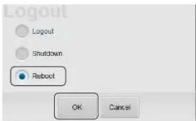
3 Tap [OK] when the confirmation screen appears.
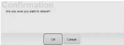
The server (including the IMB) reboots.
Notes
• The projector itself will not reboot.
- If the projector's lamp is lit, it will turn off and the projector will enter the cooling state.
Shutting Down the System
1 Tap on the upper right of the screen.
2 Select [Shutdown], and then tap [OK].

3 Tap [OK] when the confirmation screen appears.

The projection system will shut down. The MAIN indicators and LAMP indicators on the rear of the projectors will turn to blinking green while cooling. Once cooling is complete, the LAMP indicators will turn to solid red. Leave the system as it is at this point.
4 Once the MAIN and LAMP indicators turn solid red, and the main projector's IMB indicator begins blinking red (the sub projector's IMB indicator will remain red), move the power switch to off (O) to turn off the power.
Caution
If, after shutdown, the power switch on the rear of a projector is not turned off and only the server is turned on, the IMB on the main projector will not power on. If this happens, the IMB indicator will blink red. Turn the power switch off, and then turn the power on again.
Operations
Sequence of Operations
The sequence of operations from receiving distributed DCP to screening operations are shown below.
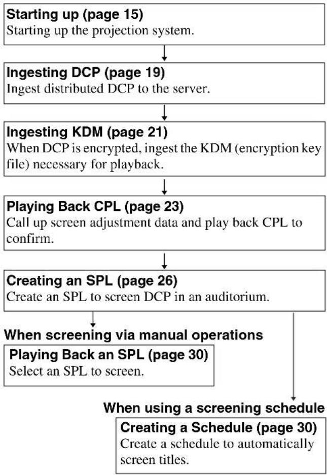
flowchart
graph TD
    A["Starting up (page 15)<br>Starting up the projection system."] --> B["Ingesting DCP (page 19)<br>Ingest distributed DCP to the server."]
    B --> C["Ingesting KDM (page 21)<br>When DCP is encrypted, ingest the KDM (encryption key file) necessary for playback."]
    C --> D["Playing Back CPL (page 23)<br>Call up screen adjustment data and play back CPL to confirm."]
    D --> E["Creating an SPL (page 26)<br>Create an SPL to screen DCP in an auditorium."]
    E --> F["When screening via manual operations<br>Playing Back an SPL (page 30)<br>Select an SPL to screen."]
    F --> G["When using a screening schedule<br>Creating a Schedule (page 30)<br>Create a schedule to automatically screen titles."]
Selecting the Projector to be Controlled
Before performing a control operation, select the target projector.
1 Tap the projector selection button at the top right of the screen.

The "Select Control Projector" dialog box will be displayed.
2 Tap the [Selected Projector] button to select a projector, and then tap [Apply].

The selected projector and the available control operations will be displayed on the screen.
Ingesting DCP
This procedure ingests DCP, such as the main feature to be screened, or previews, to the server.
Notes
- When DCP is encrypted, the KDM encryption key file is necessary.
- Depending on the USB HDD type being used, the following messages may be displayed on the center of the screen. These do not indicate problems.
"Unable to mount Audio Disc"
"Unable to mount Utility_**USB HDD model number**"
For details on ingesting KDM, see "Ingesting KDM" (page 21).
Note
When ingesting DCP/KDM, be sure to do so with the power switches on the server and projector set to on. In such cases, be sure to verify that the IMB indicator on the main projector is lit green.
DCP can be ingested in the following ways.
- Ingesting from HDD via USB Connector (page 19)
- Ingesting from HDD via CRU DATAPORT (page 20)
- Ingesting via Network (page 21)
Ingesting from HDD via USB Connector
Caution
Do not start up the server with a USB device inserted in INGEST PORT1/2 connector on the front of the server. The USB device may not be recognized.
1 Connect the HDD containing the DCP to the server's INGEST PORT 1/2 connector.
2 Tap the [Library] tab, and then tap [Library]. The "Library" screen will be displayed.
3 In the [External Folder] pane, select the following terminals connected to the HDD, and then tap [Open].
- When connected to INGEST PORT 1 terminal, select [Ingest_USB_1].
- When connected to INGEST PORT 2 terminal, select [Ingest_USB_2].

The content inside the HDD connected to INGEST PORT 1/2 will be displayed.
However, folders with the following character strings (regardless of case) will not appear.
bin, boot, dev, etc, home, initrd, lib, misc, opt, proc, root, sbin, selinux, srv, tmp, sys, usr, var
4 Select the DCP ( ) to ingest, and then tap [Ingest].
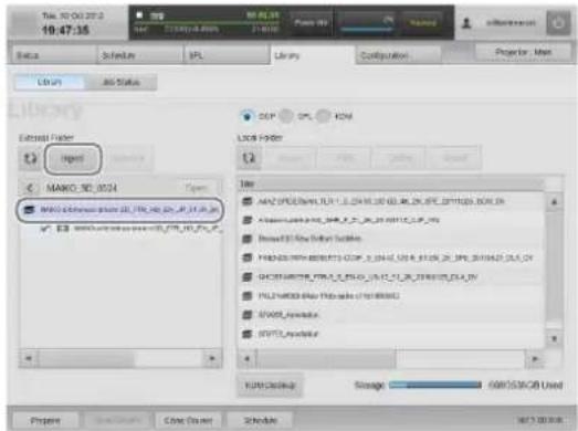
Notes
- Select the CPL ( ) within DCP and tap [Ingest] to ingest the selected CPL only as new DCP.
• To refresh the displayed content, tap .
The selected DCP will be ingested into the server. Tap [OK] to close the message.

5 To continue ingesting multiple DCPs, repeat step 4. The DCP ingest request will be registered as the following job.
6 After DCP has been ingested, select the following terminals connected to the HDD, and then tap [Unmount].
- When connected to INGEST PORT 1 terminal, select [Ingest_USB_1].
- When connected to INGEST PORT 2 terminal, select [Ingest_USB_2].
You can now safely remove HDDs.
How to export ingested DCP
1 In the [External Folder] pane, select the export destination.
2 In the [Local Folder] list, select a DCP to export, and then tap [Export].
How to confirm progress of ingesting/exporting DCP
You can tap [Job Status] in the [Library] tab to display the "Job List" screen and check the progress and status of ingestion.

The following operations are available for each button in the [Job List] pane.
[Pause]: Suspends jobs
[Resume]: Reopens jobs
[Cancel]: Cancels jobs in progress.
[Remove]: Deletes jobs
Note
If you pause a job and then remove it, the next job will enter a paused state. Tap [Resume] to resume that job.
To check ingested DCP
Ingested DCP can be checked in the “Library” screen’s [Local Folder] list.
Select [DCP] to display DCP ingested to the server in the [Local Folder] list.

The following operations are available for each button in the [Local Folder] list.
[Edit]: The name of the selected DCP can be changed.
[Details]: Detailed information on the selected DCP will be displayed.
[Delete]: The selected DCP can be deleted.
Note
To refresh the displayed content, tap
Ingesting from HDD via CRU DATAPORT
A CRU DATAPORT carrier is necessary to use the CRU DATAPORT. For further details, contact qualified Sony service personnel.
1 Insert the HDD containing DCP to the server's CRU DATAPORT.

natural_image
Diagram of a file transfer or storage device with an open drive and a folder, showing no text or symbols.2 For further instructions, follow steps 2 to 6 in "Ingesting from HDD via USB Connector" (page 19) to ingest DCP.
In step 3 and 6, select [Ingest_SATA] in the [External Folder] pane.
To remove the HDD
Perform the following to remove the HDD.

①Press the power button.
The LED blinks for a moment and then turns off.
②Verify that the LED is off, push the left side of the handle, and remove the HDD.
Ingesting via Network
DCP stored on another server can be ingested via network.
Caution
To ingest DCP via network, it is necessary to register the source device ahead of time.
For further details, refer to the "Installation Manual."
To ingest DCP, follow steps 2 to 5 in “Ingesting from HDD via USB Connector” (page 19).
In step 3, select the source device in the [External Folder] pane.
Ingesting KDM
When DCP is encrypted, it is necessary to also ingest the KDM encryption key file to the server.
When DCP is encrypted, a key icon will be displayed on any CPL containing DCP.
DCP can be opened in the "Library" screen.

KDM can be ingested in the following ways.
- Ingesting from a USB Flash Drive (page 21)
- Ingesting from a Network Folder (page 22)
Ingesting from a USB Flash Drive
Caution
Do not start up the server with a USB device inserted in INGEST PORT1/2 connector on the front of the server. The USB device may not be recognized.
1 Connect the USB flash drive containing the KDM to the server's INGEST PORT 1/2 connector.
2 Tap the [Library] tab, and then tap [Library]. The "Library" screen will be displayed.
3 In the [External Folder] pane, select the following terminals connected to the USB memory device, and then tap [Open].
- When connected to INGEST PORT 1 terminal, select [Ingest_USB_1].
- When connected to INGEST PORT 2 terminal, select [Ingest_USB_2].
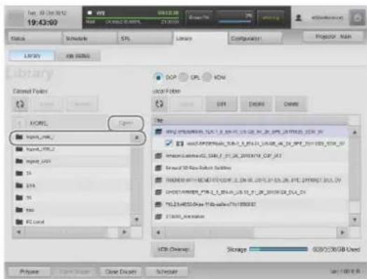
The content on the USB memory device inserted in INGEST PORT 1/2 will be displayed.
4 Select the KDM ( ) to import, and then tap [Ingest].

Note
To refresh the displayed content, tap
The selected KDM is ingested to the server. Tap [OK] to close the message.

5 Confirm that the ingested KDM has been applied to the DCP.
For further details, see "To confirm that KDM has been applied" (page 22).
Note
You can ingest KDM from the CRU DATAPORT. For instructions, see steps 1 to 2 in “Ingesting from HDD via CRU DATAPORT” (page 20), and steps 1 to 4 in “Ingesting from a USB Flash Drive” (page 21). For steps on how to remove an HDD, see "To remove the HDD" (page 21).
Ingesting from a Network Folder
If a KDM is copied to a preset network folder, it will be automatically ingested.
For details on network folder settings, see the "Installation Manual".
Execute the following steps to ingest to a network folder that has not been set.
1 Tap the [Library] tab, and then tap [Library]. The "Library" screen will be displayed.
2 Select a network folder, select the KDM you want to ingest, and then tap [Ingest].

The selected KDM is ingested to the server. Tap [OK] to close the message.

3 Check that the ingested KDM has been applied to the DCP.
For details on operations, see "To confirm that KDM has been applied" (page 22).
To confirm that KDM has been applied
1 In the [Library] tab's "Library" screen, tap The displayed content will be refreshed.
2 Tap the desired DCP to open it and confirm that the ingested KDM is displayed underneath the applicable CPL.
When KDM has not been ingested, "No Key" will be displayed.

To confirm the KDM time limit
After selecting the [KDM] radio button in the "Library" screen, select a KDM in the [Local Folder] pane, select a KDM to check, and then tap [Details] to check the period of validity.
Deleting unnecessary KDM files
Tap [KDM Cleanup] to delete KDM that are not related to DCP.
Playing Back CPL
Calling up Screen Adjustment Data
Depending on the content's signal classification (viewing angle (HD/scope/flat)) for playback, screen adjustment data can be called up when registered in the function memory. Settings such as zoom ratio, and brightness are recorded in the adjustment data.
For details on the function memory or adjustment data, refer to the "Installation Manual."
When switching functions (i.e., adjustment data), the main and sub projectors must both be selected and switched individually to functions of identical numbers and names. If function switching is included in an SPL, the functions on both projectors can be switched simultaneously.
For details, see "Creating an SPL" (page 26)
1 In the [Status] tab's "Auditorium" screen, tap [Projector].

The "Projector Control" screen appears.
2 Select the adjustment data appropriate to the content from the [Function] list, and then tap [Load].

The adjustment data will be loaded into the projector.
3 Tap [CLOSE] at the bottom of the screen to close the screen.
The lens mounted on the projector can be checked in the "Status" tab's "Auditorium" screen.
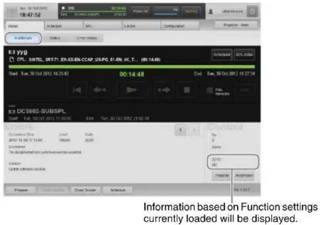
For details on how to change the lens, see “Attaching and Removing the Lens” (page 42).
To fine-tune the adjustment data
You can fine-tune the adjustment data for the main and sub projectors separately. Use the projector selection button to select the projector for which to perform fine-tuning, and perform the following using the buttons in the “Projector Control” dialog box.
[Lamp Power]: Adjusts the screen brightness
[Zoom]: Adjusts the screen size
[Focus]: Adjusts the screen focus
[H]: Adjusts the horizontal position of the screen
[V]: Adjusts the vertical position of the screen
Caution
Be aware that when you tap [Save] for either the main or sub projector, the fine-tuned adjustment data will overwrite the setting values of the function number selected in the [Function] list for the respective projector.
Selecting a CPL
Notes
- When in Schedule Playback mode, tap [Scheduled] or [Manual] (the display will change) to set to Manual mode, or select the [Play Manually] check box. [Play Manually] is convenient for temporary playback of tests while in Schedule Playback mode.
- When [Play Manually] is selected and the manual playback and scheduled playback overlap, the content played back last will take priority.
1 In the [Status] tab's "Auditorium" screen, tap [Load].

The "Load Content" screen will be displayed.
2 Select the [CPL] radio button to display the "CPL" list, select a CPL for playback, and then tap [Load].

The selected CPL will load, and will be displayed in the “Auditorium” screen.

Playing Back CPL
Using buttons in the "Auditorium" screen, CPLs can be played back, paused, or cued to a certain position, and they can be checked for missing files or damaged tracks.

During CPL playback, the playback progress is displayed on the progress bar.
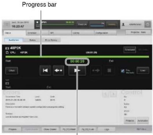
Elapsed time (current position)
Control buttons Description
| (Play back from the beginning) | Plays back the CPL from the beginning. This button is displayed while content is paused. |
| (Playback will start from the previous 30 seconds.) | The playback position will rewind 30 seconds and playback will begin. This button is displayed while content is paused.When the elapsed time does not total 30 seconds, playback will start from the beginning. |
| (Pause) Pauses playback.This button is only displayed during playback.While paused, the last displayed frame will remain on the screen. | |
| (Play) Plays back a CPL.This button is displayed while content is paused or stopped. | |
| (Playback will start from the previous 5 minutes in advance.) | The playback position will advance 5 minutes and playback will begin. This button is displayed while content is paused.When the current remaining time is more than 30 seconds, but less than 5 minutes, you can tap this button to play back the final 30 seconds of Duration.When the remaining time is less than 30 seconds, playback will start from the stop location. |
| (Stop) Stops playback.This button is displayed during playback. | |
Creating an SPL
Create an SPL to show DCP in an auditorium.
In an SPL, the screening order of a CPL for a single screening, and automatic controls for theater facilities during a screening are defined.
Function (i.e., adjustment data) switching can also be added as a cue in an SPL.
In such cases, the functions on both projectors will switch simultaneously (i.e., the function numbers and function names will be identical on both projectors) in response to a single switching operation.
Alternatively, when using the standard method of switching functions without SPLs, the main and sub projectors must both be selected and switched individually to functions of identical numbers and names.
Creating an SPL
Create a new SPL.
In addition to CPLs, you can add cues such as completed SPLs and lighting controls to an SPL.
1 Tap [SPL] in the [SPL] tab.
The "SPL List" screen will be displayed.
2 Tap [New].

The SPL setting screen will be displayed.
3 Enter the SPL title in [SPL Title].
You can enter up to 128 alphanumeric characters and symbols, excluding quotation marks (").
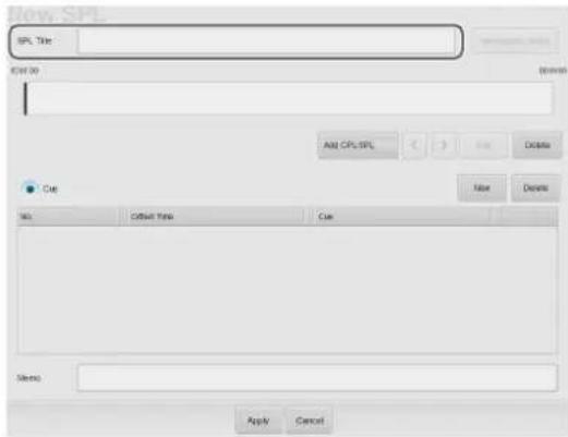
4 Tap [Add CPL/SPL].
The SPL/CPL/Cue list will be displayed.
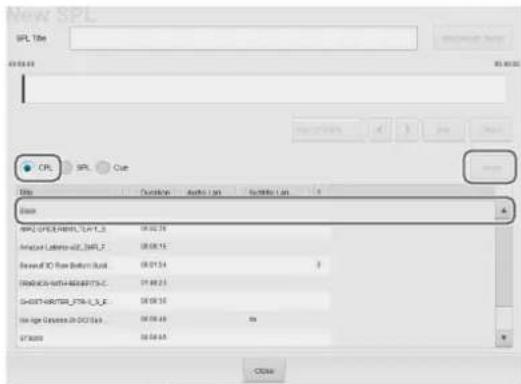
5 Select the [CPL] radio button, select the CPL from the list that you want to add to the SPL, and then tap [Insert].
To insert in a black screen (Black), select "Black" and then tap [Insert]. Next, set the time for the black screen (Black), and then tap [Apply].
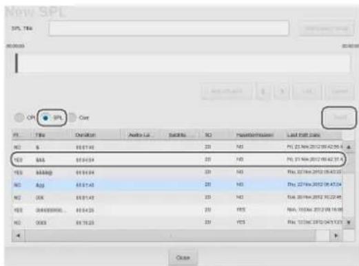
6 To add the completed SPL to an SPL, select the [SPL] radio button, select the SPL from the list that you want to add, and then tap [Insert].
Notes
- List operations can be carried out with the following buttons.
[<] / [>]: Changes the CPL or SPL order
[Delete]: Deletes the selected CPL or SPL
[Edit]: Changes the length of the black screen (Black) when that option is selected
- You can insert a CPL or SPL and change the order by dragging and dropping the CPL or SPL.
- Up to about 10 CPLs or SPLs should be inserted in a single SPL. If you want to create an SPL that includes more than 10 CPLs, create SPLs that include about 10 CPLs each, and then combine the SPLs.
- Continuing black screens (Black) will be automatically merged into a single black screen (Black) with a total length of all screens combined. Caution: When a CPL or SPL is deleted using [Delete], and black screens (Black) exist at both ends of the CPL or SPL, they will be automatically merged.
- If you want to replace a registered CPL or SPL, insert a CPL or SPL to replace and then delete the registered CPL or SPL.
7 Tap [Close] to close the list. The added content will be displayed.
Caution
The cue and the CPL inserted in the added SPL will not be displayed.
8 To insert control cues for lights and other theater facilities in an SPL, tap [New].
When configuring events (cues) of multiple GPIO pulse types to the SPL, place them so that they are longer than the pulse intervals.
A cue will be added to the list.
9 Select the insertion time and type of cue. To delete the inserted cue, tap [Delete].
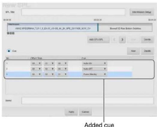
Caution
When a cue has been inserted, you should check to see that the cue is executed before screening content.
Notes
• Network commands can be sent as cues (controls triggered via GPIO or via network commands).
For details on configuring cues, refer to the Installation Manual.
- Commands can also be sent to the LKRA-PCAB1 as cues.
For details, see "Periodic Calibration Using SPLs" (page 40).
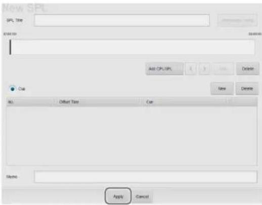
10 Tap [Apply].
To set an intermission, see "Setting an Intermission in the SPL" (page 28).
The setting will be saved and added to the SPL list.

To change the content of an SPL
Select the SPL you want to change from the SPL list and tap [Edit]. The SPL setting screen will be displayed, and you can change the content there.
For details, see step 3 and beyond of “Creating an SPL” (page 26).
To copy an SPL
You can copy the content of a SPL, add a different title, and use it to create a new SPL.
1 In the SPL list, select the copy source, and then tap [Copy].
2 Enter the SPL title, and then tap [Apply].

The SPL will be created.
To delete an SPL
In the SPL list, select the SPL you want to delete, and then tap [Delete]. Once the confirmation message is displayed, tap [OK] to delete the SPL.
Procedures for importing/exporting SPL
You can import and use an SPL that was created on another projection system, and export schedules created on the current projection system.
Note
SPL import and export can only be performed from a computer.
Exporting an SPL
Select the SPL and click [Export]. When the download screen of the browser appears, save the file.
Normally, the file is saved to the downloads folder. After downloading is complete, we recommend renaming the file to a name that is easy to remember.
Importing an SPL
Click [Import]. When the upload screen of the browser appears, select the SPL file and click [Open].
Note
When you click [Import], a dialog will be displayed.
- To assign a new UUID when importing an SPL, select "New SPL UUID".
- To use the same UUID as when exporting, select "Old SPL UUID".
- When importing an SPL that contains a Sub SPL, select "Old SPL UUID" and import the Sub SPL first.
Setting an Intermission in the SPL
You can set an intermission anywhere in the CPL registered to the SPL.
To set an intermission, insert the intermission at the desired position while playing back the CPL.
1 In the SPL list, select the SPL you want to add an intermission to, and then tap [Edit]. The SPL setting screen will be displayed.
2 Tap [Intermission Setup].
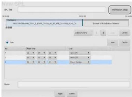
The intermission setting screen will be displayed.
3 Set the intermission.
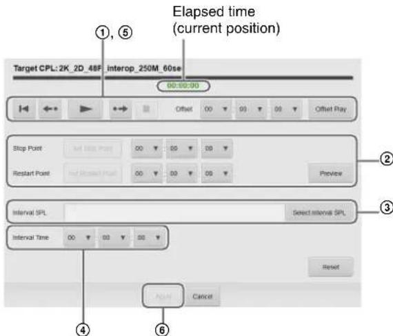
①Set the position where you want to insert the intermission.
Using the operation buttons, play back the CPL and tap [Set Stop Point] at the position you want to add the intermission. Similarly, tap [Set Restart Point] where you want to restart playback.
The set time will be entered in ② [Stop Point] and [Restart Point].
For an explanation of how to use the control buttons, see "Playing Back CPL" (page 25).
②Adjust the time as required.
③Tap [Select Interval SPL] and select the SPL to play during the interval period (Interval SPL).
④Specify the interval period.
⑤Using the control buttons, play back the CPL to confirm intermission operation.
⑥Tap [Apply].
The intermission will be set.
Note
Only one intermission can be set per SPL.
Triggering SPL Playback Using GPI Signals
You can use a GPI signal as a trigger to start playing back an SPL.
1 Tap [GPI Triggered] in the [SPL] tab. The “GPI Triggered” screen will be displayed.
2 Select the GPI signal, and then tap [Edit].

The “Edit GPI-triggered SPL” screen will be displayed.
3 Specify the duration for which playback is enabled.
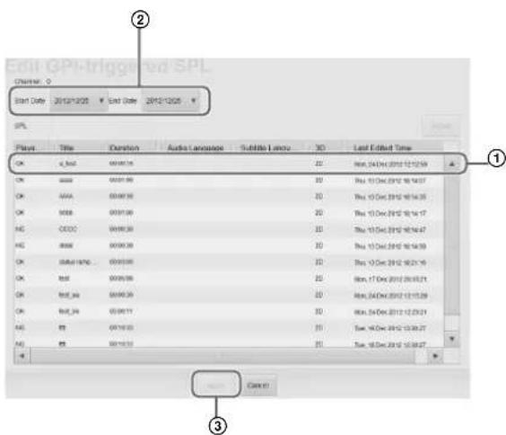
①Select the SPL for which to start playback.
②Determine the duration for which the playback will be enabled, and change the start and end dates.
③Tap [Apply].
Note
Tap [Details] to display detailed information on the selected SPL.
Playing Back an SPL
Play back a created SPL.
This section describes steps for manual playback of SPLs.
For instructions on how to create a screening schedule, see "Creating a Schedule" (page 30).
Selecting an SPL
Notes
- When in Schedule Playback mode, tap [Scheduled] or [Manual] (the display will change) to set to Manual mode, or select the [Play Manually] check box. [Play Manually] is convenient for temporary playback of tests while in Schedule Playback mode.
- When [Play Manually] is selected and the manual playback and scheduled playback overlap, the content played back last will take priority.
Select an SPL for playback in the [Status] tab's "Auditorium" screen.
Operations are the same as for selecting a CPL.
See "Selecting a CPL" (page 24).
Playing Back an SPL
Using buttons in the "Auditorium" screen, SPLs can be played back, paused, or cued to a certain position. Operations are the same as for CPL playback.
See "Playing Back CPL" (page 25).
Note
If you stop an SPL while it is in progress, the cues located after the stopped position will not be executed.
To check the detailed information of an SPL
In the “Auditorium” screen, tap [SPL Detail] to check detailed information on the currently loaded SPL.
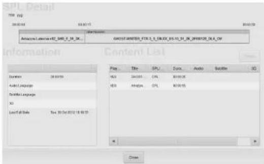
Creating a Schedule
The schedule is a function that allows you to automatically play back an SPL at a set time.
Note
For scheduled playback, it is necessary to tap [Scheduled] / [Manual] (the display will change) in the [Status] tab's "Auditorium" screen and select [Scheduled].
Creating a Schedule
1 Tap the [Schedule] tab.
The "Schedule" screen will be displayed.
2 Tap [New].

The schedule setting screen will be displayed.
3 Set the schedule.

①Select the SPL from the SPL list that you want to set to the schedule.
To check detailed information on the SPL, select an SPL and tap [Details].
②Select whether the schedule is a one-time event, or repeating. To set a one-time event, select the [One Time] radio button, and to create a repeating schedule select the [Repeat] radio button.
③Set a date to execute the schedule.
- When the [One Time] radio button has been chosen, set the date to execute the schedule. - When the [Repeat] radio button has been chosen, set the time period to execute the schedule.
④Add a check mark to receive triggers (notifications) from other systems, to begin playback, and coordinate with other systems.
For information on triggers, refer to the "Installation Manual."
⑤Tap [Apply].
The schedule will be saved and reflected in the "Schedule" screen.
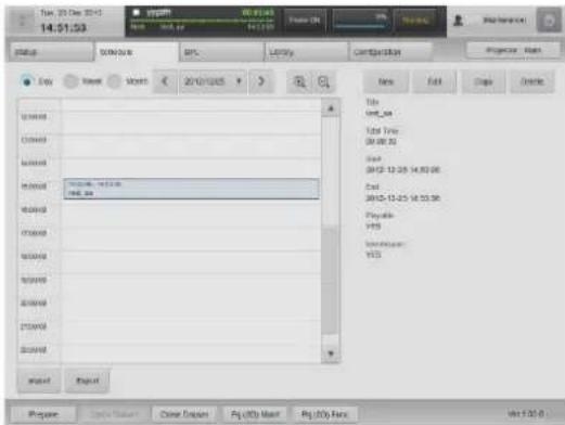
4 Repeat step 3 to set another schedule in a different time slot.
As preparation for each CPL showing may take several seconds, the show durations for SPLs that include multiple CPLs may be longer than expected (As a guideline, “Number of CPLs × 6”). As a result, such shows may not finish before the scheduled start time of the next show, depending on the content. In such cases, the next show will not start.
Notes
- The same processing will be applied whether the [Week] or [Month] radio button is selected.
- Schedules can be moved via drag-and-drop, however, this option is not available when the [Month] radio button is selected.
- When using the unit with a connected computer, it is necessary to match the computer's regional and time settings with the regional and time settings of
this unit. For details on settings, refer to your computer manual.
To copy schedules
You can copy a set schedule to another time slot.
1 In the "Schedule" screen, select a source schedule to copy, and then tap [Copy].
2 Set the copy destination and then tap [Apply].
For details on setting items, see step 3 in "Creating a Schedule" (page 30).
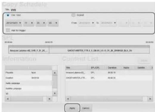
The schedule will be copied.
Importing/Exporting Schedules
You can import and use a schedule that was created on another projection system, and export schedules created on the current projection system.
Notes
- For schedule import and export, operations are only available from a computer.
- Import the necessary SPL before importing schedules.
To import schedules
1 In the bottom left of the "Schedule" screen, click [Import]. The file selection screen appears.
2 Select the schedule file to import, and click [OK]. The schedule will be imported, and it will be displayed on the "Schedule" screen.
To export schedules
1 In the bottom left of the "Schedule" screen, click [Export]. The "Schedule Export" screen will be displayed.
2 Select a schedule period to export, and then click [Apply].

The schedule file is exported. Schedule files are normally stored in the downloads folder. After downloading is complete, we recommend renaming the file to a name that is easy to remember.
Projecting Images Using an External Playback Device
Images can be projected on a screen from a playback device connected to the projector.
Note
It is necessary to create an HDMI input function memory beforehand.
1 Connect the external playback device to the projector's HDMI IN 1/2 connector.
2 Call up the adjustment data for the external playback device registered to function memory.
For details on how to call up the adjustment data, see "Calling up Screen Adjustment Data" (page 23).
3 Project the images on an external playback device.
Note
Audio signals included in HDMI cannot be output from the audio output connector of this unit.
Manually Controlling Theater Facilities
Using touch panel monitor controls, you can control various theater facilities, such as opening and closing the curtain, and controlling the lights.
It is necessary to make some initial connections and adjust settings to control theater facilities.
For further details, refer to the "Installation Manual."
Note
You can also register theater facility controls to the SPL to automatically execute them.
For further details, see "Creating an SPL" (page 26).
1 In the [Status] tab, tap [Auditorium]. The “Auditorium” screen will be displayed.
2 Tap [Automation] in the [Control] pane.

3 Tap the button for the control you want to execute.

The control will be executed.
4 Tap [Close] to close the screen.
Note
Network commands can also be executed as automations.
Others
Opening/Closing the 3D Filter
Ordinarily, the 3D filters held in the 3D filter holders open and close on the left side of the projectors when viewed from the front. However, depending on the operating environment, they may be installed so that they open outward to the left and right. In such cases, the lock pin of the filter that opens to the right is located at the bottom of the holder.
Standard installation
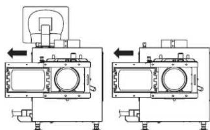
natural_image
Technical line drawing of two mechanical components with mounting brackets and internal chambers (no text or symbols)Left/right opening installation
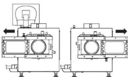
natural_image
Technical line drawing of two mechanical components with directional arrows indicating motion (no text or symbols)Illustrations of a standard installation are used for the explanations in the following sections.
Opening the 3D Filter
Pull out the 3D filter in the direction of the arrow. Even if you pull the filter all the way out, it will not fall out of the holder due to the lock pin.

natural_image
Technical line drawing of a mechanical assembly with no visible text or symbolsClosing the 3D Filter
Pull the lock pin in direction A to release the lock, and slide the 3D filter back into place.

natural_image
Technical line drawing of a mechanical assembly with labeled component A, showing internal components and motion direction (no text or symbols beyond labels)Calibrating the Screen
The LKRA-PCAB1 (herein referred to as the “calibration camera”) can be used to automatically calibrate deviations that may occur in the convergence between the two projectors that comprise the dual system. You can perform calibration using the LCD panel and touch sensor via simple operations with each calibration operation taking about 5 minutes (when [STATIC] is selected for [OPTION] - [CALIBRATION MODE]).
Installing the Calibration Camera
Caution
- Install the calibration camera in a stable location free from vibration.
- Connect the calibration camera to a UPS. If the camera's power supply is cut while calibration using SPLs is in progress, server operations may become unstable.
- Make sure that there are no obstructions between the calibration camera and screen.
- Make sure the calibration camera's lens is clean.
- When installing the calibration camera in a projection room, adhere to the following.
- Keep the projection room as dark as possible.
- Install the calibration camera close to the glass, and use blackout curtains, for example, to prevent light from the projector or reflections from other light sources in the room from entering the calibration camera.
- Install the calibration camera so that the T = (distance between the screen and calibration camera in m) / (screen width in m) value is between 1.05 and 4.0.
- As a general reference, install the camera within 1m of the screen's center axis.
Connecting the Calibration Camera to the Projectors
1 Stabilize the calibration camera on a tripod, for example.
2 Connect each cables as illustrated.
Connect the USB cables (not supplied) only when performing calibration using SPLs.

flowchart
graph TD
    A["Server"] -->|AC power supply| B["UPS"]
    B -->|USB cable (USB 2.0)| C["Connection cable (RS-232C)"]
    C --> D["Main projector"]
    C --> E["Sub projector"]
    C --> F["Connection cable (RS-232C)"]
    B --> G["AC power supply"]
    G --> H["Supplied AC adapter"]
    H --> I["Calibration camera"]
    I --> J["USB connector"]
    I --> K["CTRL1"]
    I --> L["CTRL2"]
    L --> M["to AC adapter"]
    M --> N["to INGEST PORT 1 connector on server"]
    N --> O["to RS-232C connector on main projector"]
    N --> P["to RS-232C connector on sub projector"]
The calibration camera turns on, and the following main menu appears in the LCD panel.
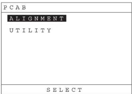
ENTER
LCD Panel Displays
When navigating menus
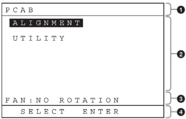
①Menu level
②Menu
③Warning message area
④ Function name
When an application is being executed
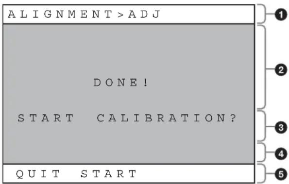
①Application name
②Status
③Notification
④ Warning message area
⑤Function name
During camera pass-through mode
A "T" mark appears at the bottom right of the screen. The aspect ratio of the image displayed during camera pass-
through mode differs from that of the actual image and appears horizontally compressed.

natural_image
Blue gradient screen with a square frame and dark border, no visible text or symbolsApplication names and functions will appear when you operate the touch sensor. However, the display will return to camera pass-through mode after a short time.
When an error occurs
![ALIGNMENT > CAL [ EXX ] CAL : CENTER OVER QUIT](/content/2026/05/902519/images/5678a2427b747397847c85958a9501ddf01037b42a989ff1dbf2cdc51dc16894.jpg)
①Application name
② Application error
③Warning message area
④Function name
For details on error codes, see "Error Code List (LKRA-PCAB1)" (page 48).
Preparation
Perform the following preparations to ensure proper calibration.
1 Run the two projectors for at least 30 minutes.
2 Manually adjust the projectors. To ensure proper calibration, be sure to manually adjust the projection area size, center position, and brightness of each projector so that they approximately match before using the calibration camera's application. (Such adjustments are ordinarily performed during installation.)
If the positions of the two projectors' screens are not sufficiently aligned beforehand, calibration via the calibration camera's application may result in error.
Caution
This step is not required ordinarily, as manual adjustment is performed during initial installation. However, if the positions of the projectors have shifted significantly since installation, readjustment is required.
3 Ingest the DCP for adjustment, and play back the CPL.
The calibration camera's application must be performed with the same alignment CPL being played back from both projectors.
Select CPLs for which the mask configurations for the target screen and projector function settings match, and manually adjust the screen with the CPL in a paused state.
Caution
For details on the alignment DCP, contact qualified Sony service personnel.
4 Check the ambient light.
Make sure the area around the screen is as similar as possible to the actual screening conditions.
Spotlights or other bright lights near the screen may result in calibration errors.
Performing Calibration
Touch sensor notation
In this manual, touch sensor functions are indicated as follows.
FX [XXXXXX]
FX: Indicates the corresponding touch sensor button (F1, F2, or F3).
[XXXXXX]: Indicates the function name.
Caution
Do not operate the server via touch panel monitor or browser operations while using the calibration camera. If such operations are performed, the calibration camera's functions may not operate properly. If a function does not operate properly, return to the main menu and start the procedure over from the beginning.
1 Tap [ALIGNMENT] while the main menu is displayed, and then tap F3 [ENTER].

2 Tap [CALIBRATION], and then tap F3 [EXEC].

The calibration sequence will start according to the mode and settings configured in [OPTION] - [CALIBRATION MODE] and [OPTION] - [PJT THROW RATIO]. Be sure to configure the [OPTION] - [CALIBRATION MODE] and [OPTION] - [PJT THROW RATIO] settings beforehand.
[OPTION] - [CALIBRATION MODE]
[STATIC]: Corrects distortions in the sub projector's projected image using the main projector's image as a reference, superimposing both images. As adjustments based on previous calibration values, calibration times will be shorter with smaller shifts in the projected images. Use this setting under normal circumstances.
[TRACE]: Corrects distortions in the sub projector's projected image using the main projector's image as a reference, overlaying both images on each other. The main projector will only be adjusted if calibration on the sub projector alone is insufficient. As adjustments based on previous calibration values, calibration times will be shorter with smaller shifts in the projected images.
[AVERAGE]: Corrects distortions in both the sub projector and main projector's projected images
using the average amount of shifting between the two projectors as the target value, minimizing the amount of correction and improving the overlay accuracy between adjustment points. As distortion correction values are reset with each calibration process, calibration times may be longer than with other modes.
[OPTION] - [PJT THROW RATIO]
Select the appropriate value from the following, according to [THROW RATIO] of the target projector for adjustment.
[1.2 to 4.0]: Select this when the throw ratio of the target projector for adjustment is 1.2 to 4.0.
[1.05 to 1.2]: Select this when the throw ratio of the target projector for adjustment is 1.05 to 1.2. In addition, select this value if adjustment of the camera's position is difficult with the [1.2 to 4.0] setting.
Note
When you select the aspect ratio of the target projector for calibration in [OPTION] - [PJT THROW RATIO], the test pattern will switch and the camera position and zoom will be adjusted in step 4, according to the setting.
3 Check the test pattern, and confirm whether manual adjustment of the projectors was performed properly. If manual adjustment was not performed properly, tap F1 [QUIT] and repeat the procedure from "Preparation" (page 37).
Note
Depending on the screen, you can tap F2 [SCOPE] or F2 [FLAT] to switch the test pattern according to the mask configurations for the target screen and projector function settings.
4 Tap F3 [START].
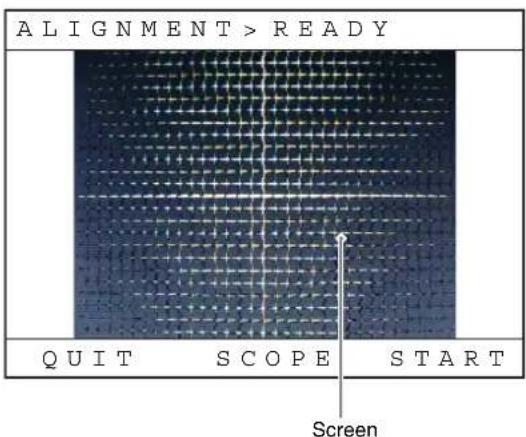
Manually adjust the camera's position so that the red frame (center frame) near the center of the LCD panel display appears within the approximate center of the screen. The zoom is adjusted automatically.
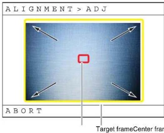
If a flashing yellow frame (target frame) appears in the LCD panel display, make fine adjustments to the calibration camera's position so that the screen fits within the frame.
After the zoom process is properly completed, the following screen appears.
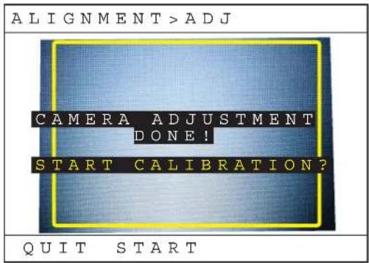
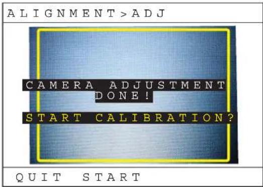
5 Verify that the four areas in the test pattern displayed on the calibration camera are not significantly askew. If they are significantly askew, make fine adjustments to the calibration camera's position to achieve proper horizontal and vertical alignment. If you want to move the calibration camera or otherwise retry the adjustment process, tap F1 [QUIT].
6 Tap F3 [START].
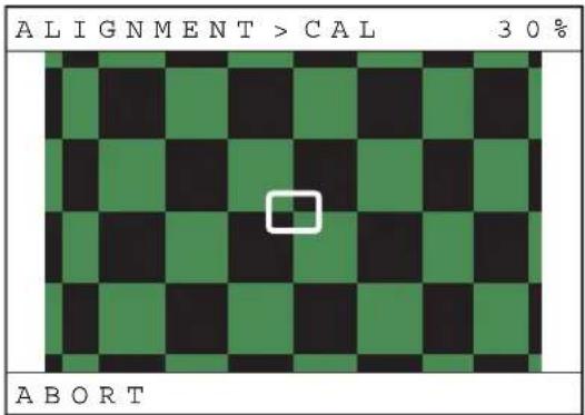
Calibration starts automatically. During calibration, the target frame will automatically move to the current point of calibration.
Caution
- Do not move the calibration camera while calibration is in progress.
- Prevent obstructions from entering the space between the calibration camera and screen.
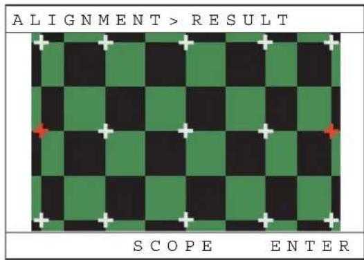
7 When the "Convergence Adjust" test pattern appears, check the calibration results.
Confirm the color of the markers on the calibration points of the captured calibration image.
Green: Calibration successful.
Amber: Calibration errors exceed the specific margin of error. Be sure to verify the image visually.
Red: Divergence exceeds the scope of electronic calibration. Adjust the projectors manually, and then try performing calibration again.
8 Tap F3 [ENTER].
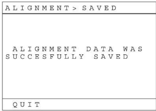
9 Tap F3 [SAVE].

To quit the application without saving, tap F2 [QUIT].
10 Tap F1 [QUIT] to quit the application.
Periodic Calibration Using SPLs
You can create a calibration SPL and register it to a schedule to perform periodic calibration with the calibration camera. (Only for Ver.1.50 or later.)
Notes
- A calibration CPL must be ingested beforehand.
-
For details on the CPLs to be used, contact qualified Sony service personnel.
-
The content displayed on the calibration camera's display during calibration using SPLs differs from that displayed during manual calibration. (only “REMOTE CTRL MODE” appears at the center of the display.)
- If the calibration camera's power supply is cut during SPL execution, server operations may become unstable.
1 Create the calibration SPL.
① Perform steps 1 to 4 in “Creating an SPL” (page 26) to create a new SPL.
② Add the calibration CPL to the SPL. Select the [CPL] radio button, and select the calibration CPL from the list, and then tap [Insert].
③Add the function switching cue to the SPL. Select the [Cue] radio button, and select the function switching cue for calibration from the list, and then tap [Insert].

Set the offset to "00:00:30."
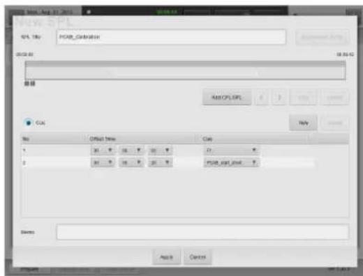
④Add the calibration execution cue to the SPL. Select the calibration start cue (PCAB_start_short) from the list, and then tap [Insert]. Set the offset to "00:01:00."
2 Register the calibration SPL that you created to the schedule. Select the appropriate calibration frequency (daily, weekly, etc.).
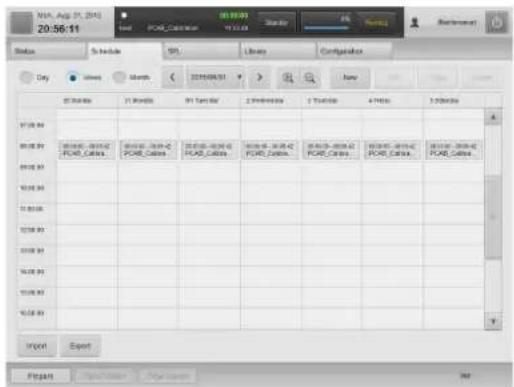
For details, see "Creating a Schedule" (page 30).
Attaching and Removing the Lens
Before changing the lens
The projection system must be shut down, and the projector switch must be set to off before changing the lens.
Caution
Changing the lens while the power is on may damage the projector.
1 Shut down the projection system.
2 Move the projector power switch to the off position.
For detailed steps, see "Shutting Down the System" (page 17).
Removing the Lens
1 Press the lock button all the way, and after the lock is released, press and hold the lock button and lift the lens fixing lever toward 🔒

Caution
If you lift the lever without pressing the lock button, the lock button and lever will be damaged. Be sure to press the lock button and make sure the lock is released before lifting the lever.
2 Remove the lens from the projector while firmly holding the lens not to drop it.
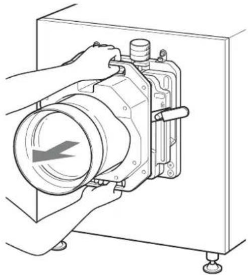
natural_image
Line drawing of a mechanical device with hands operating it, no text or symbols presentAttaching the Lens
1 Confirm that the lens fixing lever is in the position.

natural_image
Technical line drawing of a mechanical device with mounting feet and internal components (no text or symbols)Lens fixing lever
2 Attach the lens to the projector while firmly holding the lens not to drop it and aligning the position.
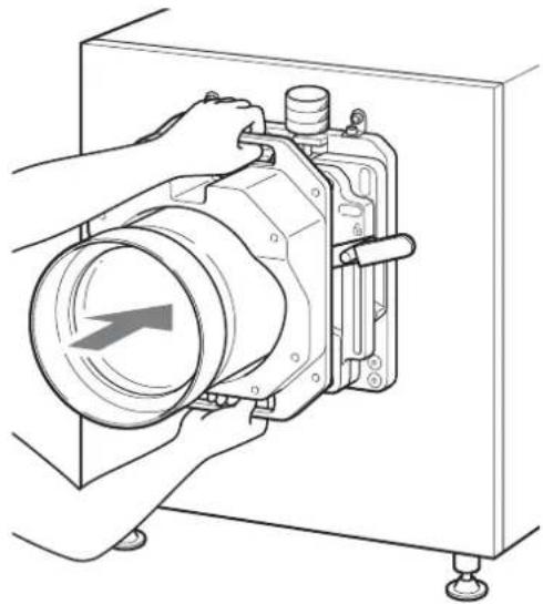
natural_image
Line drawing of a mechanical device with hands operating it, no text or symbols presentCaution
When attaching the lens to the projector, insert it straight.
3 While supporting the lens, lower the lens fixing lever while the lens flange and shift base level are contacting each other.

natural_image
Technical line drawing of a mechanical device with mounting base and internal components, showing a rotational arrow indicating motion (no text or symbols present)Caution
If locked while there is a gap between the lens flange and shift base level, the lens flange base will become warped. Be sure to attach the lens while supporting it. Make sure there are no gaps in the 4 locations on the shift base level.

How to Read the Indicators
The following indicators show the status of the projector.
Projector (rear)
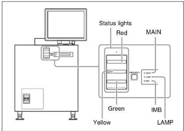
Projector (IMB)

Server (front)

The relationship between the way the indicators light and the device's status is shown in the following table.
Projector (rear) (status indicators)
| MAIN LAMP Device status | ||
| Lit red Lit red Standby mode | ||
| Lit green Blinkinggreen (rapid) | Starting up | |
| Lit green Lit green Power on (lamp on) | ||
| Lit green Blinkinggreen (slow) | Power on (lamp off) | |
| Blinkinggreen (rapid) | Blinkinggreen (rapid) | Shutting down or cooling |
Projector (rear) (status indicators)
| IMB Device status |
| Lit red Standby mode |
| Lit green Access from server or start-up complete |
| Blinking green (rapid) Shutting down |
| Blinking red (rapid) Shutdown completeAfter shutting down the server, it is necessary to turn the power switch on the rear of the projector off and on again. |
Projector (rear) (status lights)
| Status light Device status | |
| Lit green System stable and projector on, standby mode, or lamp off | |
| Blinking green System shutting down | |
| System starting up | |
| Ingesting | |
| Playing | |
| Projector status changing | |
| Blinking yellow | Minor error |
| Blinking red | Severe error (hardware malfunction, show failure) |
| Off | Power off |
Projector (IMB section) (Status indicator)
| STATUS 1 | Device status |
| Solid red Start-up | |
| Solid orange | Connecting to the server |
| Solid green | Connection to server complete |
| STATUS 2 | Device status |
| Solid red TMB section error | Contact qualified Sony service personnel |
| Solid green | Normal |
Caution
If STATUS 1 indicator does not turn solid green even after a few minutes when connected to the server, contact qualified Sony service personnel.
Server (front)
| POWER | Device status |
| Lit red Standby mode | |
| Blinking green (rapid) Starting up, shutting down | |
| Lit green | Startup complete |
Caution
When the MAIN indicator is solid red and the IMB indicator is solid green, do not set the power switch on the rear of the projectors to OFF. After shutting down from the server, set the power switch on the rear of the projectors to off.
HDD1 indicator: Shows that the hard disk drive for the system is being accessed.
HDD2 indicator: This indicates the RAID access containing the DCP.
Troubleshooting
Check this section before consulting qualified Sony service personnel. If the unit still does not function properly, consult qualified Sony service personnel.
To check installation/connections
In the "Status" window, check to make sure that the lens mount, lamp mount, and server connection are properly married.
1 In the [Status] tab, tap [Auditorium] and check that the lens is correctly mounted.
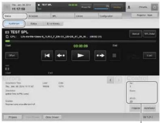
A message about the lens mounting can be seen here.
2 Tap [Status] and confirm that the lamp for each item is lit solid green.
Lamp mounting Server connection

Lamps
Lamp colors show the health status of each part of the unit.
Green: normal
Yellow: warning (title will continue to be shown)
Red: error (title will stop)
Note
If the lamp is lit yellow or red, check the "Status – Auditorium" screen's [Solution] message for a solution.

The solution will be displayed here. Follow the instructions to deal with the problem.
The projector does not turn on
- Confirm that the lamp access panel (lamp grill) is firmly attached. If the lamp access panel (lamp grill) is not completely attached, the projector will not turn on.
- Check to make sure the exhaust duct fans are operating. If the exhaust duct fans are not operating, the projector will not turn on.
There is something wrong with the screen/the screen is too bright/the screen is too dark
Confirm that the correct screen adjustment data for the playback content has been called up.
For further details, "Calling up Screen Adjustment Data" (page 23).
Screen is too dark
The brightness may be lowered due to deterioration of the lamp. Check how long the lamp has been used in the "Status – Status" screen, and change the lamp if necessary.
For further details, refer to the "Maintenance Manual."
When operating the screen, a dialog box appears with a stopped process confirmation dialog
If this happens, tap [Continue] to continue the process. If you add a check mark to [Don't ask me again] this dialog will no longer be displayed.
Screenshot
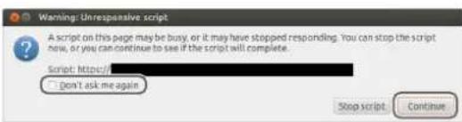
Caution
If you tap [Stop script], processing will stop and normal operation may be hindered.
Cannot shut down
Unplug the power cord connected to the rear of the server.
The projector switched to standby during playback
When the projector switches to standby during playback due to events such as sudden power outages, use the touch panel monitor to shut down after screening is complete, and then restart the system.
If you cannot shut the unit down using the touch panel monitor, unplug the power cord connected to the rear of the server, reconnect the cord, and then start the system.
Error Code List (LKRA-PCAB1)
| Error code Category Error message Possible cause Solution | |||
| E01 PIT:(Projector Communication) | NO CONNECTION • The calibration camera and projectors are not connected via the supplied connection cables. | • Check the connections, and make sure the supplied connection cables are connected properly. | |
| • Use new connection cables. For details on replacement, contact your local Sony representative. | |||
| • Turn on the projector's main power by setting the switch to on (I). | |||
| E02 NO COMM • The calibration camera's CTRL2 | connector and the main projector's RS-232C connector are not connected via the supplied connection cable.• The calibration camera's CTRL2 connector is connected to a device other than the main projector. | • Check the connections, and make sure the supplied connection cables are connected properly. | |
| • The connection cables are damaged. | • Use new connection cables. For details on replacement, contact your local Sony representative. | ||
| • The SDCP protocol's "Community" is set to a setting other than "SONY." | • Check the "Community" setting. | ||
| E03 UNCONTROLLABLE • The projector is not running. • Verify that the MAIN indicators and LAMP indicators are lit green. | |||
| E06 CAM:(Camera Communication) | NO COMM • The calibration camera's connection cable is disconnected. | • Check the connection, and make sure the cable is connected properly. | |
| • Contact your local Sony representative. | |||
| E43 ADJ:(Adjustment) NO SCREEN | • The screen is not within the shooting range of the calibration camera. | • Adjust the position of the calibration camera so that the screen is within range.• Lower the ambient light. | |
| E53 NO WINDOW • The test pattern is not detected near the center of the calibration camera's frame. | • Adjust the position of the calibration camera so that the cross cursor displayed in the LCD panel appears on the test pattern. | ||
| E54 XPT DETECTION | • The calibration points on the screen are not detected. | • Lower the ambient light.• Play back an adjustment CPL with the same screen aspect ratio as the [OPTION] - [PIT THROW RATIO] setting.• Adjust the position and zoom of the calibration camera so that the four sides of the test pattern displayed in the LCD panel appear as vertically and horizontally straight as possible.• Adjust the position of the calibration camera so that reflected light from the port glass does not enter the camera. | |
| Error code | Category | Error message | Possible cause | Solution |
| E55 | OUT OF SCREEN • The calibration camera's position | • Return to the main menu, and perform calibration again. | ||
| has shifted after its position and zoom were adjusted. | ||||
| E56 | RE-FOCUS • The calibration points on the | |||
| screen are not detected, even after the focus is fine-tuned. | ||||
| E61 | CAL:(Calibration) CENTER OVER • The center positions of the two projectors are outside the scope of electronic calibration. | • Reset the distortion correction values. (Refer to the digital cinema dual system's Installation Manual.)• Return to the main menu, and perform calibration again so that the centers of the to projectors are as close to each other as possible. | ||
| E62 | UNKNOWN SIGNAL • The image used for adjustment is not detected. | • Verify that the adjustment CPL is being played back. | ||
| E63 | NO CENTER POINT • An error had occurred with the image used for adjustment.• The calibration camera cannot detect the image. | • Return to the main menu, and perform calibration again. | ||
| E64 | CAMERA SHAKE • The calibration camera shifted during calibration. | |||
| E65 | OUT OF RANGE • An abnormal test pattern is displayed.• The projectors cannot be controlled. | • Check the installation environment of the calibration camera. (Refer to the digital cinema dual system's Installation Manual.)• Return to the main menu, and perform calibration again. | ||
Specifications
SRX-R515 Digital Cinema Projector\*
* The dual system consists of two of these projectors.
Optical system
Projection method
1.48 inch, 4K, SXRD (3)
Resolution (H x V)
4096 × 2160 pixels
Lamp 450 W, high-voltage mercury (HPM)
lamp (6)
or 330 W, high-voltage mercury (HPM) lamp (6)
Contrast 8,000:1 (average)
Light output 15,000 lumens (center) (LKRM-U450
450 W lamp)
Input/output
Video input HDMI (2)
Audio output Unbalance, 8 channels, 24 bit, 48/96 kHz, linear PCM, D-sub 25 pin (female) (1)
AES/EBU, 16 channels, 24 bit, 48/96 kHz, linear PCM, D-sub 25 pin (female) (1)
* Audio signals included in HDMI cannot be output from the audio output connector of this unit.
Playback format
JPEG 2000 4K 2D: 24p
2K 2D: 24p/25p*/29.97p*/30p*/48p/60p
2K 3D: 24p/29.97p*/30p*/48p/60p
MPEG-2**
MP@HL, YUV420 /422 8 bit, 80 Mbps
(max.) bitrate, 1920 × 1080,
23.98p/24p/25p
* Digital watermarking (Watermarking) is not supported.
** Digital watermarking (Watermarking) and playback of subtitle files are not supported.
General
Power 200 V - 240 V AC, 50/60 Hz, single
phase, 21.5 A - 18 A
External dimensions
548 × 634 × 1,119 ~mm
(21^5/8× 25× 44^1/8 inches) (W/H/D)
(Including lens shift block and feet.
Excluding touch panel monitor and projection parts (Status lights, ducts, etc.))
Weight Approx. 145 kg (319 lb.) (Excluding
touch panel monitor and lamp)
Operating temperatures
5 °C to 35 °C (41 °F to 95 °F)
Operating humidity
35% to 85% (without condensation)
Storage temperatures
-20^ to +60^ (-4^ to +140^)
Storage humidity
10% to 90%
Supplied accessories
• Key for removing housing (5)
• Safety Regulations (1)
or
Before Using This Unit (1)
- TPC adapter (1 set)
- Cable clamper (2)
XCT-S10 Digital Cinema Server
Input/output
Ingest
USB 3.0 (2)
CRU DATAPORT (open slot) (1)
System control
GPI (8)
GPO (16)
D-sub 9 pin, female, for audio processor control (1)
USB 2.0, for UPS control (1)
Network
Gigabit Ethernet (2)
Storage
HDD
4 TB (Expandable to 8 TB),
Modified RAID 6
General
Power 100 V - 240 V AC, 50/60 Hz, single
phase, 2.2 A - 1.0 A
External dimensions
482×131×560mm
(19× 5^1 / 4× 22^1 / 8 inches) (W/H/D)
Weight Approx. 24 kg (52 lb. 13 oz.)
(Serial No. xx0xxxx)
(The fifth digit from the last is "0")
Approx. 19 kg (41 lb. 14 oz.)
(Serial No. xx1xxxx)
(The fifth digit from the last is "1")
Operating temperatures
5 °C to 35 °C (41 °F to 95 °F)
Operating humidity
35% to 85% (without condensation)
Storage temperatures
-20^ to +60^ (-4^ to +140^)
Storage humidity
10% to 90%
Supplied accessories
- Feet (1 set)
• PCI express cable (2 m) (1)
- Ethernet cable (2 m) (1)
LKRA-007 Touch Panel Monitor
Optical system
Screen size 15 inch
Resolution (H × V)
$$ 1 0 2 4 \times 7 6 8 \text { pixels (XGA) } $$
General
Power Touch panel monitor: 12 V DC, 1 A
AC adapter: 100 - 240 V AC, 50/60 Hz
External dimensions
$$ 3 5 0 \times 3 1 0 \times 5 7 \mathrm{mm} $$
$$ \begin{array}{l} (1 3 ^ {7} / _ {8} \times 1 2 ^ {1} / _ {4} \times 2 ^ {1} / _ {4} \text { inches }) (\mathrm{W/H/} \ \mathrm{D}) \end{array} $$
Weight Approx. 3.6 kg (7 lb. 15 oz.)
Operating temperatures
$$ 5 ^ {\circ} \mathrm{C} \text { to } 3 5 ^ {\circ} \mathrm{C} (4 1 ^ {\circ} \mathrm{F} \text { to } 9 5 ^ {\circ} \mathrm{F}) $$
Operating humidity
$$ 35 \% \text{ to } 85 \% \text{(without condensation)} $$
Storage temperatures
$$ - 2 0 ^ {\circ} \mathrm{C} \text { to } + 6 0 ^ {\circ} \mathrm{C} (- 4 ^ {\circ} \mathrm{F} \text { to } + 1 4 0 ^ {\circ} \mathrm{F}) $$
Storage humidity
$$ 10\% \text{ to } 90\% $$
Supplied accessories
- AC adapter (1)
• VGA cable (1)
- USB cable (1)
LKRA-010 Dual System Accessory Kit
Components DIF-243 boards (2)
Shield plates (2) (for main projector and sub projector)
Conduit (1)
Conduit supports (2)
Tamper harnesses (3)
Conduit mounting screws (4)
Conduit support mounting screws (4)
Mass Approx. 10 kg (Approx. 22 lb. 8.0 oz.)
(total weight of components)
Conduit length 4.7 m (5 yd. 5^-1/_8 in.) (excluding conduit box)
Supplied accessories
Before Using This Unit (1)
LKRA-011 3D filter and holder
Dimensions Approx. 390 × 325 × 346 to 504 mm
(Aprox. 15^3 / 8× 12^7 / 8× 13^5 / _8 to
19 ^/_8 in.) (width/height/thickness)
(including protrusions)
Thickness direction changes by adjusting at installation.
Mass Approx. 10.5 kg (Approx. 23 oz. 2.4 lb.)
(including LKRA-006 equivalent 3D filter)
Supplied accessories
Filter bracket attaching screws M8 (8)
Hexagonal spacers (8)
Washers (8)
Spring washers (8)
Filter attaching screws M4 (8)
Before Using This Unit (1)
LKRA-PCAB1 Projector Auto Calibration Box
Power requirement
DC 12 V, 600 mA
Power consumption
7.5 W (max)
Dimensions 105 × 124 × 163 mm ( 4^-1/4 × 5 × 6^-1/2 in.)
(height/width/depth)
Mass Approx. 1.3 kg (Approx. 2 lb. 14 oz.)
Operating temperature
5^ to 35^ (41 °F to 95 °F)
Operating humidity
35% to 80% (without condensation)
Storage temperature
-20^ to +60^ (-4^ to +140^)
Storage humidity
20% to 90%
Supplied accessories
AC adapter (1)
Connection cables (2)
Before Using This Unit (1)
Design and specifications are subject to change without notice.
Notes
• Always make a test recording, and verify that it was recorded successfully.
SONY WILL NOT BE LIABLE FOR DAMAGES OF ANY KIND INCLUDING, BUT NOT LIMITED TO, COMPENSATION OR REIMBURSEMENT ON ACCOUNT OF FAILURE OF THIS UNIT OR ITS RECORDING MEDIA, EXTERNAL STORAGE SYSTEMS OR ANY OTHER MEDIA OR STORAGE SYSTEMS TO RECORD CONTENT OF ANY TYPE.
• Always verify that the unit is operating properly before use. SONY WILL NOT BE LIABLE FOR DAMAGES OF ANY KIND INCLUDING, BUT NOT LIMITED TO, COMPENSATION OR REIMBURSEMENT ON ACCOUNT OF THE LOSS OF PRESENT OR PROSPECTIVE PROFITS DUE TO FAILURE OF THIS UNIT, EITHER DURING THE WARRANTY PERIOD OR AFTER EXPIRATION OF THE WARRANTY, OR FOR ANY OTHER REASON WHATSOEVER.
- SONY WILL NOT BE LIABLE FOR CLAIMS OF ANY KIND MADE BY USERS OF THIS UNIT OR MADE BY THIRD PARTIES.
- SONY WILL NOT BE LIABLE FOR THE LOSS, REPAIR, OR REPRODUCTION OF ANY DATA RECORDED ON THE INTERNAL STORAGE SYSTEM, RECORDING MEDIA, EXTERNAL STORAGE SYSTEMS OR ANY OTHER MEDIA OR STORAGE SYSTEMS.
- SONY WILL NOT BE LIABLE FOR THE TERMINATION OR DISCONTINUATION OF ANY SERVICES RELATED TO THIS UNIT THAT MAY RESULT DUE TO CIRCUMSTANCES OF ANY KIND.
3D
| 3D Format Resolution | Frame rate | |
| Frame Packing (progressive) | 1280 × 720 | 59.94p/60p |
| Frame Packing (progressive) | 1280 × 720 | 50p |
| Frame Packing (progressive) | 1920 × 1080 | 23.98p/24p |
| Top & Bottom | 1920 × 1080 | 59.94p/60p |
| Top & Bottom | 1920 × 1080 | 50p |
| Top & Bottom | 1920 × 1080 | 23.98p/24p |
| Top & Bottom | 1280 × 720 | 59.94p/60p |
| Top & Bottom | 1280 × 720 | 50p |
| Side by Side 1280 × 720 | 59.94p/60p | |
| Side by Side | 1280 × 720 | 50p |
| Side by Side | 1920 × 1080 | 59.94p/60p |
| Side by Side | 1920 × 1080 | 50p |
| Side by Side | 1920 × 1080 | 59.94i/60i |
| Side by Side | 1920 × 1080 | 50i |
HDMI signals
The unit can handle up to the following HDMI signals.
2D
| Resolution Frame Rate | |
| 720 × 480 59.94p/60p | |
| 720 × 480 59.94i/60i | |
| 720 × 576 50p | |
| 720 × 576 50i | |
| 1280 × 720 59.94p/60p | |
| 1280 × 720 50p | |
| 1920 × 1080 59.94p/60p | |
| 1920 × 1080 50p | |
| 1920 × 1080 23.98p/24p | |
| 1920 × 1080 59.94i/60i | |
| 1920 × 1080 50i | |
| VGA (640 × 480) 60 | |
| XGA (1024 × 768) 60 | |
| UXGA (1600 × 1200) 60 | |
| WUXGA (1920 × 1200) 60 | |
| 2048 × 1080* | 23.98/24 |
| 2048 × 1080* | 60 |
* Sony's original specification.

- Digital Cinema Dual System
- Operating Instructions
- Table of Contents
- Overview
- Items to Check
- Operations
- Others
- Trademarks
- Please Read This First
- Notations Used in This Guide
- Manual Structure
- Safety Regulations (SRX-R515P)
- Before Using This Unit (SRX-R515, LKRA-010, LKRA-011, LKRA-PCAB1)
- Installation Manual
- Operating Instructions (this guide)
- Maintenance Manual
- Service Manual
- About License
- USB HDD and USB Memory Devices That can be Used on INGEST PORT 1/2 of This Unit
- Recognized Folder Names
- On Security
- System Configuration Example
- Part Names and Functions
- SRX-R515 Digital Cinema Projector
- Front
- ①8-inch duct attachment part
- ② Lens fixing lever
- ③ Lens attachment part
- Rear
- ①Status lights
- ②EMERGENCY switch
- ③STATUS MESSAGE window
- ④Status indicators
- ⑤Power switch
- When turning the power off
- Left side
- ① Lamp access panel (lamp grill)/ventilation holes (intake)/air filter
- ②Ventilation holes (intake)/air filter
- Connector block: Main projector
- Connector block: Sub projector
- XCT-S10 Digital Cinema Server
- ① POWER indicator
- ② SYSTEM SW switch
- ③ (IFDD) 1/2 indicator
- ④ Ventilation holes (intake)/air filter
- ⑤INGEST PORT 1/2 connector
- ⑥CRU DATAPORT
- LKRA-007 Touch Panel Monitor
- Right side
- Caution
- Bottom
- ③TPC connector
- ④Power input connector
- LKRA-011 3D filter and holder
- ①Lock pin
- ②3D filter holder
- ③3D filter
- LKRA-PCAB1 Projector Auto Calibration Box
- ①Indicator B
- ②Indicator A
- ③ Calibration camera
- ④Tripod hole
- ⑤LCD panel
- ⑥ Touch sensor
- ⑦Projector status LED
- ⑧ GND connector
- ⑨CTRL1 connector
- ⑩COM connector
- ⑪Power status LED
- ⑫DC IN connector
- ⑬CTRL2 connector
- Main Screen
- ① Auditorium number
- ②Date display
- ③Next SPL title for screening
- ④SPL playback status
- ⑤ Current SPL title
- 6Progress bar
- ⑦ Elapsed showing time
- ⑧Scheduled start time of next SPL for screening / time remaining until start
- ⑨Projector status indicator / control button
- ⑩Job display button
- ⑪ Error display button
- ⑫Login user name
- (Power) button
- Main menu
- ⑮Projector selection button
- 16Playback mode display button
- ⑰Version information
- ⑱Projector information display
- 19Shortcut button
- Note
- 20Error information display
- ②Playback control button
- Startup
- Turning on the Main Power on the Projectors
- Starting up the Server
- Logging Into the System
- Notes
- To change your login password
- Changing the login user
- Starting the Projectors
- Rebooting the System
- Shutting Down the System
- Sequence of Operations
- Selecting the Projector to be Controlled
- Ingesting DCP
- Ingesting from HDD via USB Connector
- How to export ingested DCP
- How to confirm progress of ingesting/exporting DCP
- To check ingested DCP
- Ingesting from HDD via CRU DATAPORT
- To remove the HDD
- Ingesting via Network
- Ingesting KDM
- Ingesting from a USB Flash Drive
- Ingesting from a Network Folder
- To confirm that KDM has been applied
- To confirm the KDM time limit
- Deleting unnecessary KDM files
- Playing Back CPL
- Calling up Screen Adjustment Data
- To fine-tune the adjustment data
- Selecting a CPL
- Creating an SPL
- To change the content of an SPL
- To copy an SPL
- To delete an SPL
- Procedures for importing/exporting SPL
- Exporting an SPL
- Importing an SPL
- Setting an Intermission in the SPL
- Triggering SPL Playback Using GPI Signals
- Playing Back an SPL
- Selecting an SPL
- To check the detailed information of an SPL
- Creating a Schedule
- To copy schedules
- Importing/Exporting Schedules
- To import schedules
- To export schedules
- Projecting Images Using an External Playback Device
- Manually Controlling Theater Facilities
- Opening/Closing the 3D Filter
- Opening the 3D Filter
- Closing the 3D Filter
- Calibrating the Screen
- Installing the Calibration Camera
- Connecting the Calibration Camera to the Projectors
- Connect each cables as illustrated.
- LCD Panel Displays
- During camera pass-through mode
- Preparation
- Ingest the DCP for adjustment, and play back the CPL.
- Check the ambient light.
- Performing Calibration
- Touch sensor notation
- FX [XXXXXX]
- [OPTION] - [CALIBRATION MODE]
- [OPTION] - [PJT THROW RATIO]
- Tap F3 [START].
- When the "Convergence Adjust" test pattern appears, check the calibration results.
- Tap F3 [ENTER].
- Tap F3 [SAVE].
- Tap F1 [QUIT] to quit the application.
- Periodic Calibration Using SPLs
- Attaching and Removing the Lens
- Before changing the lens
- Removing the Lens
- Attaching the Lens
- How to Read the Indicators
- Troubleshooting
- To check installation/connections
- Lamps
- The projector does not turn on
- There is something wrong with the screen/the screen is too bright/the screen is too dark
- Screen is too dark
- When operating the screen, a dialog box appears with a stopped process confirmation dialog
- Screenshot
- Cannot shut down
- The projector switched to standby during playback
- Error Code List (LKRA-PCAB1)
- Specifications
- SRX-R515 Digital Cinema Projector\*
- Optical system
- Input/output
- Playback format
- General
- Supplied accessories
- Storage
- LKRA-010 Dual System Accessory Kit
- HDMI signals
Brand : SONY
Model : SRX-R515P
Category : Audio System