
1221B-10 - Range hood FRANKE - Free user manual and instructions
Find the device manual for free 1221B-10 FRANKE in PDF.


| Product Type | Under-cabinet range hood |
| Brand | Franke |
| Model | 1221B-10 |
| Installation Type | Under cabinet |
| Dimensions (Width) | 30 inches (762 mm) |
| Dimensions (Depth) | 20 inches (508 mm) |
| Dimensions (Height) | 6 inches (152 mm) |
| Weight | 25 lbs (11.3 kg) |
| Power Supply | 120V, 60Hz, 3.0A |
| Maximum Airflow | 400 CFM (cubic feet per minute) |
| Noise Level (Max Speed) | 65 dBA |
| Number of Fan Speeds | 3 |
| Lighting Type | LED, 2 bulbs |
| Light Power | 2 x 1.5W (total 3W) |
| Filter Type | Aluminum mesh, dishwasher safe |
| Ducting | 6 inch round, vertical or horizontal |
| Venting Method | Ducted or recirculating (with charcoal filter optional) |
| Control Type | Push button |
| Energy Efficiency | ENERGY STAR certified |
| Certifications | UL, cUL |
| Warranty | 1 year limited parts and labor |
| Maintenance | Clean filters monthly; replace charcoal filter every 6 months |
| Replacement Parts | Filters, light bulbs, motor assembly available |
Frequently Asked Questions - 1221B-10 FRANKE
User questions about 1221B-10 FRANKE
0 question about this device. Answer the ones you know or ask your own.
Ask a new question about this device
Download the instructions for your Range hood in PDF format for free! Find your manual 1221B-10 - FRANKE and take your electronic device back in hand. On this page are published all the documents necessary for the use of your device. 1221B-10 by FRANKE.
USER MANUAL 1221B-10 FRANKE
natural_image
Exterior view of a white stainless steel kitchen air duct (no text or symbols visible)
natural_image
Exterior view of a white air conditioner unit with open lid and ventilation slots (no text or symbols visible)
BRUKSANVISNING
Safety Instructions ....7
Instructions for use 9
Servicing and warranty....11
Electrical installation....25
Installation 26
Adjusting air flow....28

BRUKSANVISNING
Sikkerhetsforskrifter 21
Bruk....22
natural_image
Simple line drawing of a blank whiteboard with a small inset showing an arrow and a triangular symbol (no text or labels)Fig.2
natural_image
Diagram showing two mechanical components with arrows indicating motion, no text or symbols presentFig.3
Please read this installation and user guide carefully before installing and using the product, paying special attention to the safety instructions.
Save these instructions for later use or for the party who may take over the product after you.
Disconnect the product from the power supply prior to cleaning or maintenance.
§ Diversion of exhaust air must be carried out in accordance with instructions issued by the appropriate authority.
§ Exhaust air must not be directed into flues that are used for fumes from items such as gas, wood or oil-burning stoves or fireplaces.
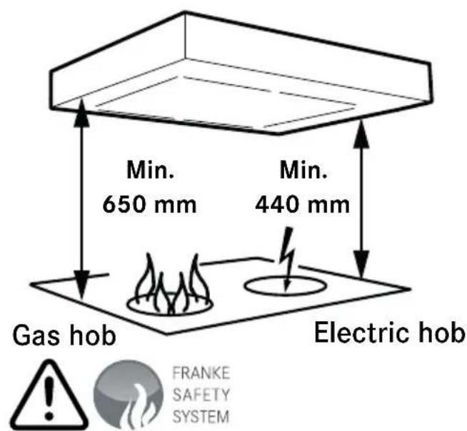
§ The distance between the stove and the product must be at least 44 cm. For gas hobs, the distance should be increased to 65 cm. Adjust accordingly if the gas hobs manufacturer recommends a higher mounting height. N.B. If the product has a stove alarm or stove guard, it must not be mounted over a gas hob. See separate instructions.
§ You must not flambé food underneath the product.
§ For safety reasons, the installation and replacement of cables or other types of connectors should only be carried out by a qualified professional.
§ If the product is to be used at the same time as products that use energy sources other than electricity, i.e., gas hobs, gas, wood or oil-burning stoves or fireplaces, etc, the room must have an adequate supply of air.
§ The product may be used by children from 8 years of age and persons with mental, sensory or physical impairment, or a lack of experience and knowledge, provided they are given information about how the product is to be used.
§ Children should not be allowed to play with the product. Children must not undertake cleaning or maintenance of the product unsupervised.
§ Accessible parts of the product may become hot when food is being prepared.
§ A fire is more likely to spread if the product is not cleaned as frequently as indicated.
N.B. The developer or proprietor is responsible for ensuring installation is carried out correctly and complies with the applicable building regulations.
GENERAL INFORMATION
The product features LED lighting (6.5 W), aluminium filters and the Easy Clean system.
FUNCTIONS

Fig. 1
A. Lighting.
B. Damper function. Open/close.
C. 1. Extension of timer (+ 30 minutes).
2. Filter guard. If the filter guard is activated (see Programming below), the LED will start to flash when the filter needs to be cleaned. After cleaning, press button C for 2 seconds to reset the system.
The damper will close automatically after 60 minutes or if you press button B again.
It is a good idea to have the damper open a short while before and after cooking to prevent cooking smells spreading into the room.
The product is fitted with a filter guard. To activate/deactivate the filter guard, see below.
Programming
- Start programming: press and hold buttons A and B for 3 seconds so that they both flash 3 times. Programming mode will then be active for 30 seconds.
- Select function: press the button for the selected function to activate/deactivate the function.
| Button Functions | |
| C Filter guard |
The LED on the button lights up when the function is activated.
- To save a programme: press and hold buttons A and B for 3 seconds. Buttons A and B will flash twice to show that the programme has been saved.
Attention!
If the product has a stove alarm or stove guard, see separate instructions.
CARE AND MAINTENANCE
Attention!
In order to ensure operation, quality and safety after servicing and maintenance, use only original parts.
Cleaning the filter
The cooker hood should be cleaned with a damp cloth and washing-up liquid. With normal usage, the filters must be cleaned at least every other month. Clean more often after intensive use.

natural_image
Simple line drawing of a blank whiteboard with a small arrow icon and a small square tag (no text or symbols)Fig. 2
Remove the grease filter by opening the snap retainer, Fig. 2.
Handle the filter carefully, taking care not to bend it.
Soak the filter in a solution of warm water and washing-up liquid. The filter can also be washed in a dishwasher.
Refit the grease filter after cleaning, making sure it snaps firmly into place.
Cleaning other parts
The inside of the cooker hood and the damper must be cleaned at least twice a year. The damper must be thoroughly cleaned in both its open and closed position using a damp cloth and washing-up liquid. Handle the damper carefully.
REPLACEMENT OF LED LIGHTING
natural_image
Diagram showing two mechanical components with arrows indicating motion, no text or symbols presentFig. 3
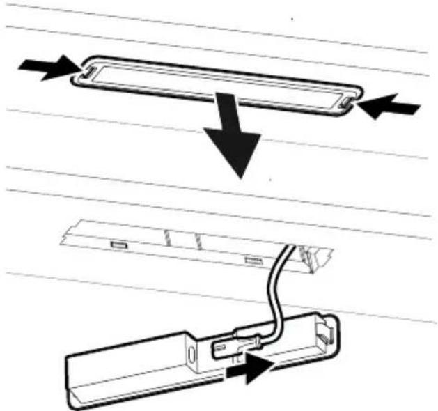
The lighting must be replaced with an equivalent special light fixture from the manufacturer or its service agent.
The lighting is removed by pressing the snap retainers from the sides and pulling the light fixture straight down so that the lighting cable can be accessed. Fig. 3
TROUBLESHOOTING
Check that the fuse is intact. Go through all the functions to check what is not working. Start by disconnecting the product from the power supply and switching it on again. Check that the connector is not bent or twisted at the connection point.
Attention!
If the product has a stove alarm or stove guard, use the separate instructions for troubleshooting.
SERVICING

Fig. 4
Before contacting servicing, check the product label and note down the FUN number, S/N number and manufacturing date of the product.
The product label is located on the left side, underneath the filter/bottom plate.
Franke Service
Tel. +46 (0)912-40 500
www.franke.se/service
They can help you fix the problem or refer you to the nearest service agent for fast and effective service.
The product is covered by the relevant AP-PLiA provisions.
ENVIRONMENTAL INFORMATION
The main raw materials used in Franke's products are:
- Metals: stainless sheet metal, galvanised sheet metal, zinc, aluminium
- Plastics: polypropylene, polyamide, polycarbonate, polybutylene terephthalate (PBT)
- Glass
All components comply with the RoHS Directive. Several of Franke's products have undergone environmental assessment by a third party. For more detailed environmental information, go to www.franke.se
PACKAGING AND PRODUCT RECYCLING
The packaging should be deposited at your nearest recycling point.

The symbol means that the product must not be treated as household waste. It should instead be taken to a collection point for the recycling of electrical and electronic components. By ensuring that the product is dealt with in the correct manner, you are helping to prevent the adverse environmental and health effects that could arise if the product was disposed of as regular waste. For further information on recycling, contact your local authority or waste disposal service, or the store where you purchased your product.
natural_image
Simple line drawing of a blank whiteboard with a small inset showing a folded paper and an arrow symbol (no text or labels)Fig. 2
natural_image
Diagram showing two mechanical components with arrows indicating motion, no text or symbols presentFig. 3
natural_image
Simple line drawing of a blank rectangular board with a small inset showing a folded paper or clip (no text or symbols)Kuva 2
natural_image
Diagram showing two mechanical components with arrows indicating motion, no text or symbols presentKuva 3
PLEIE OG VEDLIKEHOLD
Merk:
natural_image
Simple line drawing of a blank whiteboard with a small inset showing a folded paper and an upward arrow (no text or symbols)Fig. 2
natural_image
Diagram showing two mechanical components with arrows indicating motion, no text or symbols presentFig. 3
Belysningen må skiftes ut med en tilsvaren- de spesialarmatur fra produsenten eller de- res serviceagent.
Electrical connection for 230 V\~ earthed.
The product is supplied with a cable and earthed plug for connection to an earthed socket. Models -12 are also delivered with a control conductor to be connected to an external unit or set. Max connection power for control cable, 900 W at 230 V.
The socket/terminal box should be accessible after installation is complete.
If the connector is damaged, it must be replaced with an equivalent special cable from the manufacturer or their service agent.
Elektrisk tilslutning til 230 V\~ med jordforbindelse.
Produktet leveres med ledning og stik med jordforbindelse for tilslutning til jordforbundet stikkontakt. Model -12 leveres også med styrekabel for tilslutning til ekstern enhed alternativt aggregat. Maks. tilslutningseff ekt for styrekabel, 900 W ved 230 V.




ADJUSTING AIR FLOW JUSTERING AF LUFTMÆNGDE
ILMAVIRTAUKSEN SÄÄTÖ TILPASNING AV LUFTMENGDE
EN Note! Damper adjustment must be carried out by a qualified professional.
Adjusting damper: Basic ventilation is set by moving the sliding damper. The damper becomes accessible for adjustment by removing the grease filter.
Open the damper by pressing button B. Loosen stop lug G by rotating it 180° (Torx/ star screwdriver 10). Set the stop lug to the desired position. The markings on the damper correspond to the values in the "Basic flow" diagram – see following pages. The marking in the picture corresponds to position G4 in the diagram. Lock the stop lug. N.B. Make sure the lug is fully locked. Close the damper by pressing button B on the circuit breaker. Measure the pressure (Pm) at test point A to check that the flow is as required.
DA Grundventilation
EN Forced ventilation
Loosen stop lug F by rotating it 180° (Torx/star screwdriver 10). Set the stop lug to the desired position. The markings on the damper correspond to the values in the "Forcing flow" diagram – see following pages. The marking in the picture corresponds to position F8 in the diagram. Lock the stop lug. N.B. Make sure the lug is fully locked. Open the damper by pressing button B on the circuit breaker. Measure the pressure (Pm) at test point A to check that the flow is as required.
DA Forceret ventilation
line
| LpA | LwA | | --- | --- | | 40 | 44 | | 35 | 39 | | 30 | 34 | | 25 | 29 | | 25 | 25 |L_pA = Den A-vägda ljudtrycksnivån vid 10 m^2 Sabin The A-weighted sound pressure level at 10 m² by
A-mitattu äänenpainetaso, kun 10 m² Sabinia
A-veid lydtrykknivå ved 10 m² Sabin
Den A-vegtor lydtryksniveau ved 10 m² Sabin
L wA = Den A-vägda ljudeffektnivän relativt 1 pW
mula The A-weighted sound effect level relative to 1 pW
A-painotettu äänentasapaino 1 pW:n suhteen
Relativt A-veid lydeffektnivå 1 pW
Den A-vegtor lydeffektniveau relativt 1 pW
Measure valve pressure
Tryk i måleudgang. Trykk i måleuttak.
The A-weighted sound pressure level at 10 m² by Sabine's Formula
A-mitattu äänenpainetaso, kun 10 m² Sabinia
The A-weighted sound effect level relative to 1 pW
Real pressure in ventilation duct

Fig.4



- BRUKSANVISNING
- GENERAL INFORMATION
- FUNCTIONS
- Fig. 1
- Programming
- Attention!
- CARE AND MAINTENANCE
- Cleaning the filter
- Cleaning other parts
- TROUBLESHOOTING
- Franke Service
- ENVIRONMENTAL INFORMATION
- PACKAGING AND PRODUCT RECYCLING
- Kuva 2
- PLEIE OG VEDLIKEHOLD
- Merk:
- ADJUSTING AIR FLOW JUSTERING AF LUFTMÆNGDE
- ILMAVIRTAUKSEN SÄÄTÖ TILPASNING AV LUFTMENGDE
- DA Grundventilation
- EN Forced ventilation
- DA Forceret ventilation
Brand : FRANKE
Model : 1221B-10
Category : Range hood