MA4500T DSP Dante - Receiver Audibax - Free user manual and instructions
Find the device manual for free MA4500T DSP Dante Audibax in PDF.


| Product Type | Audio Receiver with DSP and Dante |
| Brand | Audibax |
| Model | MA4500T DSP Dante |
| Power Supply | AC 100-240V, 50/60Hz |
| Dimensions | 483 x 44 x 200 mm (19" rack mount, 1U) |
| Weight | Approx. 5.0 kg |
| DSP Processing | Built-in digital signal processor for routing, EQ, and dynamics |
| Dante Audio Networking | Dante-enabled for networked audio transport up to 96 kHz |
| Audio Inputs | 8 balanced XLR line inputs (switchable mic/line) |
| Audio Outputs | 8 balanced XLR line outputs |
| Control Interface | Ethernet TCP/IP for remote control and configuration |
| Frequency Response | 20 Hz - 20 kHz (±0.5 dB) |
| Total Harmonic Distortion | < 0.01% @ 1 kHz, +4 dBu |
| Signal-to-Noise Ratio | > 105 dB (A-weighted) |
| Maximum Input Level | +22 dBu |
| Maximum Output Level | +22 dBu |
| Sample Rates | 48 kHz, 96 kHz |
| Bit Depth | 24-bit |
| Cooling | Passive (fanless design) |
| Operating Temperature | 0°C to 40°C |
| Cleaning | Wipe with a dry soft cloth; avoid liquids |
| Safety | Use only supplied power cord; do not block ventilation |
| Spare Parts and Repairability | Contact Audibax support for authorized service |
Frequently Asked Questions - MA4500T DSP Dante Audibax
User questions about MA4500T DSP Dante Audibax
0 question about this device. Answer the ones you know or ask your own.
Ask a new question about this device
Download the instructions for your Receiver in PDF format for free! Find your manual MA4500T DSP Dante - Audibax and take your electronic device back in hand. On this page are published all the documents necessary for the use of your device. MA4500T DSP Dante by Audibax.
USER MANUAL MA4500T DSP Dante Audibax
natural_image
Front two black audio equipment modules with control knobs and indicator lights (no visible text or symbols on the modules themselves)MA4500T DSP / MA4500T DSP Dante
Multifunctional Network DSP Digital Power Amplifier Amplificador de potencia digital DSP de red multifuncional
INDEX / ÍNDICE
ENGLISH
WELCOME TO AUDIBAX....1
SAFETY INSTRUCTIONS....1
IMPORTANT INFORMATION......2
PACKAGE CONTENT....3
PRODUCT DESCRIPTION....3
FEATURES....3
SPECIFICATION......4
FUNCTIONAL STRUCTURE....5
INTRODUCTION TO POWER CONTROL....5
SOFTWARE INSTALLATION......5
SOFTWARE INTERFACE DESCRIPTION....7
SUPERIOR MENU....10
INTRODUCTION TO DSP FUNCTIONS....14
DISPOSAL......28
ESPAÑOL
BIENVENIDOS A AUDIBAX....9
Thank you very much for choosing Audibax. We hope you enjoy your new product.
It has been developed and designed paying attention to the smallest details, with quality control with European standards supervised by our great team of professional technicians, who work every day to offer our customers the best quality.
We make sure that every Audibax product is built to last long. All our references are made with long lasting materials and our specialists are dedicated to constantly doing quality controls to guarantee the best result.
Please read carefully this manual in order to use your Audibax product in the best way. Do not hesitate to visit our website for further information: www.audibax.com
SAFETY INSTRUCTIONS
GENERAL INFORMATION
- It is important to read and follow the instructions carefully.
- Keep all information and instructions in a secure location.
- Always follow the instructions provided.
- Take note of all safety warnings and never remove them from the equipment.
- Use the equipment only as intended and for its intended purpose.
- Ensure that the stands and/or mounts used are sufficiently stable and compatible for fixed installations. Wall mounts should be properly installed and secured, and the equipment should be installed securely to prevent falls.
- When installing the equipment, be sure to observe the relevant safety regulations in your country.
- Do not install or operate the equipment near sources of heat, such as radiators, heat registers, or ovens, and ensure that it is always cooled sufficiently and cannot overheat.
- Do not place sources of ignition, such as burning candles, on the equipment.
- Keep ventilation slits unobstructed.
- For equipment designed for indoor use only should not be used near water, flammable materials, fluids, or gases. Special outdoor equipment should be used in accordance with the manufacturer's instructions.
- Ensure that no dripping or splashed water can enter the equipment and do not place containers filled with liquids on the equipment.
- Prevent objects from falling into the equipment.
- Use the equipment only with recommended accessories intended by the manufacturer.
- Do not attempt to open or modify the equipment.
- Check all cables after connecting the equipment to prevent accidents or damage due to tripping hazards.
- During transport, take steps to prevent the equipment from falling and causing damage or injury.
- If the equipment is not functioning properly, fluids or objects have gotten inside, or is otherwise damaged, switch it off immediately and unplug it from the power outlet (if applicable). Only authorized, qualified personnel should repair the equipment.
- Clean the equipment with a dry cloth.
- Comply with all applicable disposal laws and separate plastic and paper/cardboard during packaging disposal.
- Keep plastic bags out of the reach of children.
FOR DEVICES DESIGNED TO BE CONNECTED TO THE MAIN POWER SUPPLY:
- ATTENTION: If your equipment has a power cord with a grounding plug, it must be connected to a wall outlet with a ground connection. Never remove the grounding plug from the power cord.
- If your equipment has been exposed to extreme temperature changes, allow it to reach room temperature before turning it on. Otherwise, moisture and condensation may damage the equipment.
- Before plugging in the equipment, make sure that the voltage and frequency of the power outlet match the specifications of the equipment. If the equipment has a voltage selector, only connect it to the power outlet if the values match. If the power cord or adapter does not fit your outlet, contact an electrician.
- Do not step on the power cord. Make sure it is not pinched at the outlet, adapter, or equipment connection.
- Keep the power cord or adapter within reach and disconnect the equipment from the power supply when not in use or when cleaning it. Always unplug the cord or adapter by pulling the plug or adapter, not the cord. Never touch the cord or adapter with wet hands.
- Avoid frequently turning the equipment on and off, as this can reduce its useful life.
- IMPORTANT: Only replace fuses with those of the same type and rating. If a fuse repeatedly blows, contact an authorized service center.
- To completely disconnect the equipment from the power mains, unplug the power cord or adapter from the outlet.
- If your device has a Volex power connector, the mating Volex connector must be unlocked before it can be removed. Be careful when laying cables, as the equipment can slide or fall if the power cord is pulled.
- Unplug the power cord or adapter before an extended period of disuse or in case of lightning strike risk.
- Only install the equipment when it is disconnected from the power source.
- To prevent damage and overheating, qualified personnel should regularly clean and service the equipment depending on ambient conditions like dust, nicotine, and fog.
If the product contains the following symbols, please, read carefully:
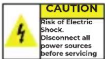
CAUTION: To reduce the risk of electric shock, do not remove cover (or back). There are no user serviceable parts inside. Maintenance and repairs should be exclusively carried out by qualified service personnel.

The warning triangle with lightning symbol indicates dangerous uninsulated voltage inside the unit, which may cause an electrical shock.
The warning triangle with exclamation mark indicates important operating and maintenance instructions.
IMPORTANT INFORMATION
CAUTION! HIGH VOLUMES IN AUDIO PRODUCTS!
This equipment is designed for professional purposes and its commercial use must comply with the applicable national rules and regulations for accident prevention.
As the manufacturer of this product, Audibax has the responsibility to inform you about the potential health risks associated with its use. One such risk is hearing damage caused by prolonged exposure to high volume.
When this product is in use, it can generate high sound-pressure levels that may cause irreversible hearing damage to performers, employees, and audience members.
To prevent this, it is important to avoid exposing yourself or others to volumes exceeding 90 dB for an extended period of time.
PACKAGE CONTENT
1 x MA2500T DSP / MA2500T DSP Dante 1 x User's manual
PRODUCT DESCRIPTION
This device is a multifunctional network DSP digital constant resistance and constant voltage power amplifier 2 * 500W @ 4Ω, 2 * 300W @ 8Ω, bridge 1000W @ 8Ω, and constant voltage 100V□1000W @ 10Ω. Real-time remote monitoring of power amplifier status, real-time setting of compressor, limiter, noise gate, parametric equalization, matrix routing, delayer and other DSPfunctions. The concise software interface provides customers with simple settings and operation experience, and multiple connection methods make it configurable and expandable, suitable for various use environments.
Application occasion:
- Performing Center
- Theater
- Stadium
- Hotel
- Conference Center
- Shopping Center
- Retail store
- Restaurant
FEATURES
- DANTE network audio optional
- Network TCP / IP control, can realize management of multiple devices
- Remote power on / off
- High resolution full color IPS LCD display
- Built-in DSP digital processor
- Support multiple connection methods: USB, TCP / IP, RS232, Rs485
- Real-time remote monitoring of the working status of the power amplifier
- Amplifier can be identified on site by software
- Support balanced XLR input and unbalanced RCA input
- Support stereo, bridge, mono, free matrix mode, one-button switching
- Two levels of adjustable input sensitivity: 0dBu / 6dBu, software or color LCD screen setting
- Power-on status can be set, Power On / Standby
- Constant voltage and resistance support: 100V, 70V, 8 ohm, 4 ohm
- Software control, can control media matrix and professional processor at the same time
- Wide voltage operation 90-260VAC
SPECIFICATION
| Model | MA4500T DSP/MA4500 DSP Dante | ||||
| Output Power | 1 OHM | 8 OHM | 16 OHM | 100V | 70V |
| All Channel | 4*500W | 4*300W | 4*150W | / | / |
| Bridge | / | 2*600W | 2*300W | 2*600W | 2*600W |
| Input vo umen | mute, phase, level detection | ||||
| Input FQ | 15band parametric equalization | ||||
| Input noise gate | start control time 1~2895ms, release time 1~2895ms, start control level -120dBu ~ -0dBu | ||||
| DSP matrix | 4*4 matrix | ||||
| Output LQ | 10 band parametric equalization | ||||
| Crossover | Butterworth, Bossel, Linkwitz slooc 6~24 | ||||
| Output delay | 4*6ms | ||||
| Output compressor | soft knce, start control level, start control lime, compression ratio, release time | ||||
| Output limiter | start control level -90dBu ~ 21dBu, release lime 1~2895ms | ||||
| Output vo umen | mute, phase, level detection | ||||
| DSP presets | 30 preset positions | ||||
| Control method | Ethernet, USB, RS/185, Rs232 | ||||
| Network specifications | TCP / IP, 1000base-T/100base-TX, Rj45 | ||||
| Channels | 4 | ||||
| Minimum output impedance | 4Ω per channel, 8Ω in bridge mode | ||||
| Input interface | Balanced 4×XLR4 Luroblock Balanced Input | ||||
| Amplification output interface | 4CH Terminal | ||||
| Cooling | Dual fan intelligent control | ||||
| Sensitivity | 6dBu sensitivity: 30dB (29.5 times); 0dBu sensitivity: 36dB (31.1 times) | ||||
| Maximum input level | 6dB sensitivity: 16dBu (1.9V) | ||||
| Signal to noise ratio | 6dBu sensitivity: 94dB; 0dBu sensitivity: 94dB | ||||
| Frequency response | 20Hz ~ 20kHz (1.0dB) @ 1W, 8Ω | ||||
| THD = N | <0.1%@1W to full power | ||||
| Sampling rate | 48K/24bit | ||||
| Channel isolation | <-70dB | ||||
| Working modes | stereo, bridged, mono, free matrix | ||||
| Remote control | remote start, standby, DSP monitoring | ||||
| Amplifier monitoring | temperature, power, voltage, current | ||||
| DANTE (optional) | 4-channel DANTE | ||||
| Display | 320x240 pixel, IPS colorful | ||||
| Output interface | 1 Balance Eurob ock | ||||
| Protection | Audio lim ter, high temperature, DC, high frequency, short circuit, back-EMF, peak current, l'miter, inrush current limiter, start-up delay, power circuit breaker protection, power supply over/under voltage protection | ||||
| PC software | software can control media matrix, audio processor, DSP power amplifier, active DSP module | ||||
| Weight | Netweight 4.2kg; Packaged weight 5.2kg | ||||
| Size | 483*300*44.5 | ||||
| Power supply | voltage input (180~264VAC) | ||||
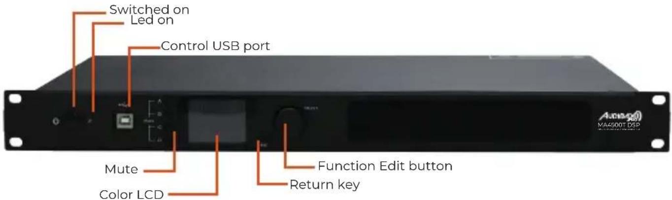
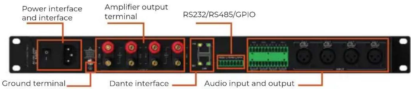
FUNCTIONAL STRUCTURE
Front Panel
Rear Panel
INTRODUCTION TO POWER CONTROL
The PowerControl control software is a management interface for the entire family of AudibaxPro MA Amplifiers, with the management software connected by Network (Cat5/6) you can manage one or all the units connected within it, either for load preset, modify inputs and/or rename units of the MA family.
In USB connection mode, you can only manage the standalone unit.
SOFTWARE INSTALLATION
Operating environment
The software is compatible for WIN7/WIN8/WIN10 any Windows x86/x64 operating system with Microsoft .NET Framework 4.0 runtime.
Software installation

data

EQPresets

img

ReadMe

AppContro
Ldll

filter.dll

FirmwareU
pdate.dll

HcU

HdL_R

kernel32.dll

Power Control

Power Control.exe

System.Data.SQLite.dll

System.Windows.Interactivity.dll

SystemSet.
dat
Run PowerControl
Open the Powercontrol folder and double-click on Powercontrol.exe. You can also choose to right-click and send a shortcut to the desktop. Within this folder, there are subfolders where the changes and/or modifications you make to the units will be stored.
Remember that to operate multiple units, they must be connected through the Ethernet port (cat-5 or 6).
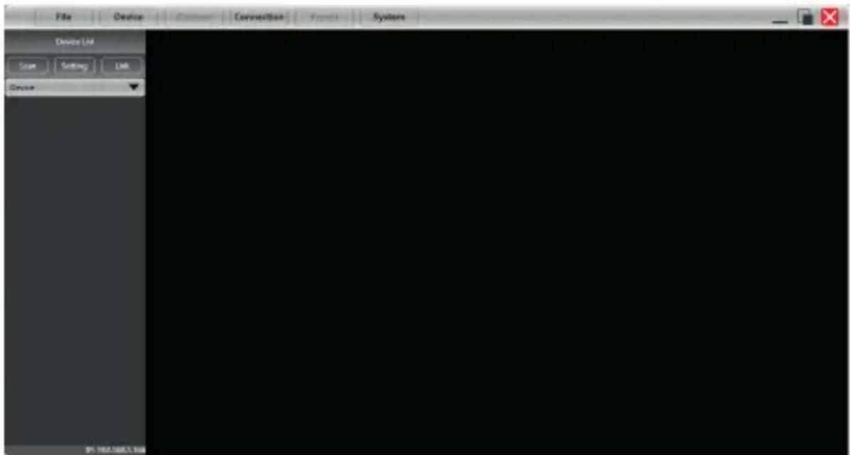
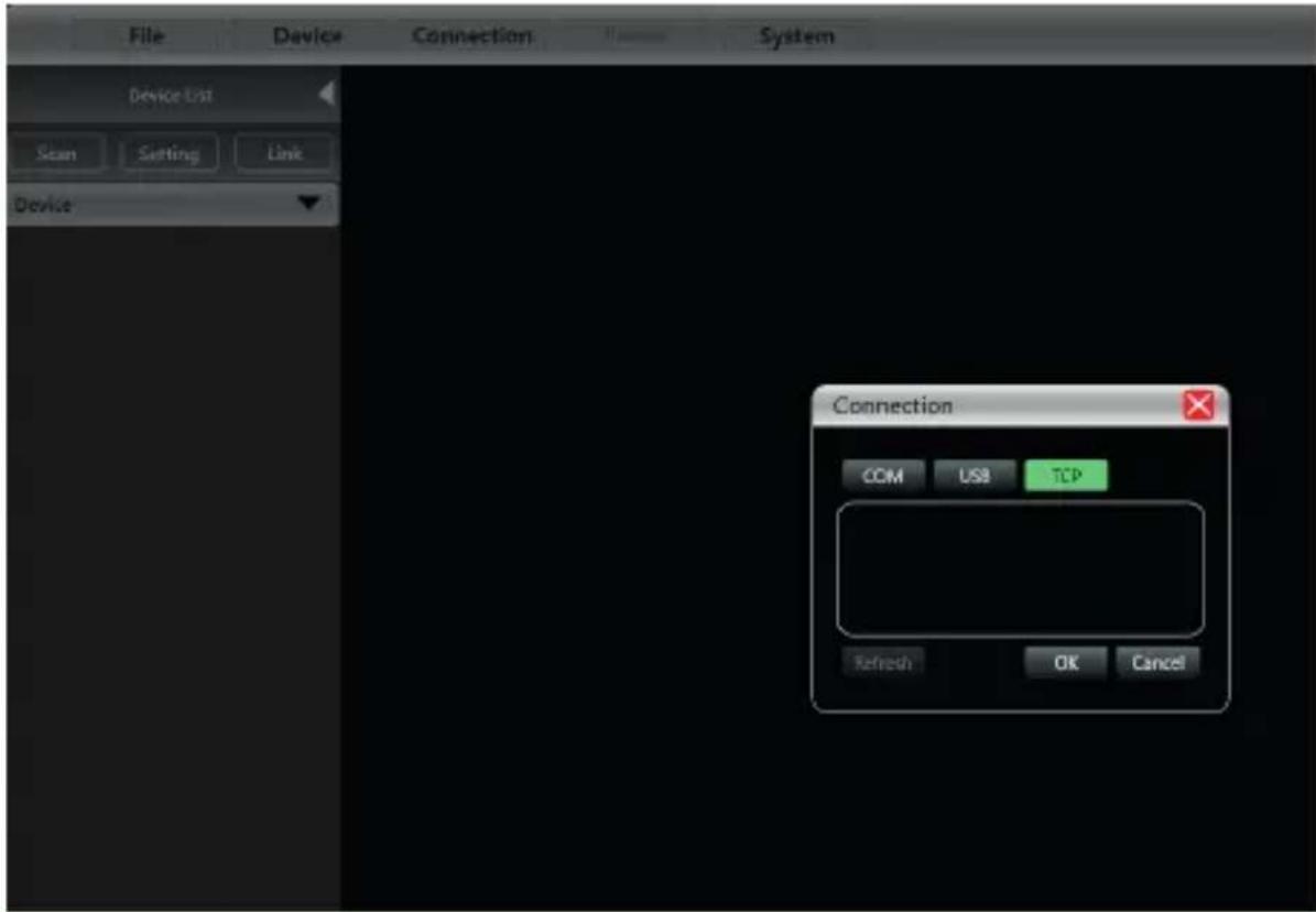
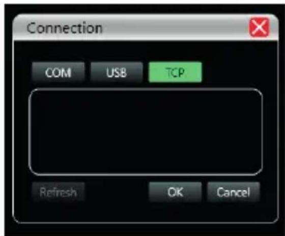
Click on "Setting" to open the connection interface, in this example we will use the "TCP" connection (Ethernet network), press Ok, and the connected units will appear in the "Device" section.
SOFTWARE INTERFACE DESCRIPTION
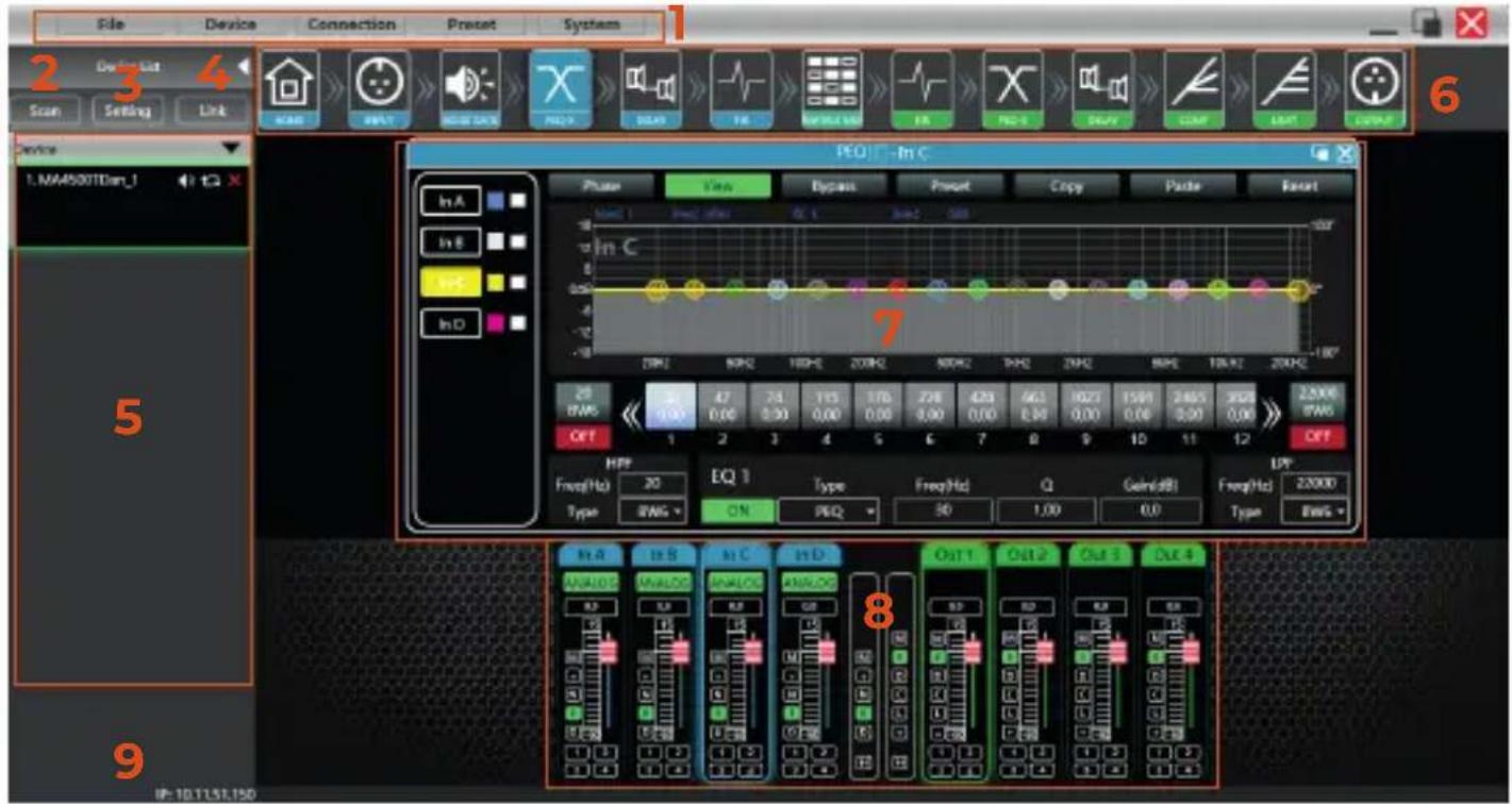
Main sections:
(1) Menu bar
(2) Unit search
(3) Control port selection
(4) Linked units
(5) Device list
(6) DSP module
(7) Unit information
(8) Entry and exit information
(9) local IP
INITIAL INTERFACE
Device settings
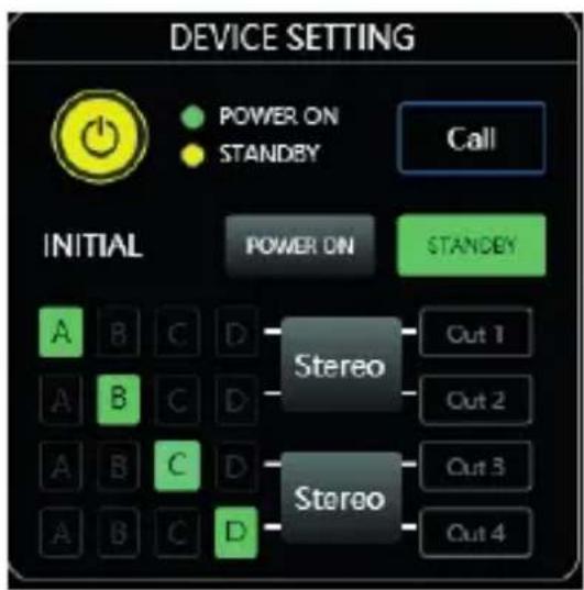
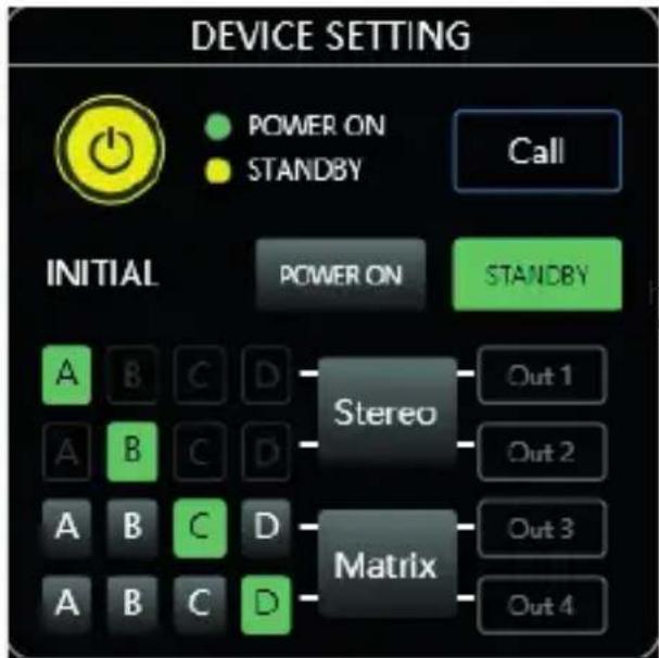
①As shown in Figure, click 📋 to switch the device between ON and STANDBY. Green is ON and yellow is STANDBY.
②Click Call to locate the selected drive. The status LED of the physical drive will start flashing to locate it.
③You can select the status of the unit (on or standby) INITIAL ON/OFFON ON/ON/ON once you press the selection, the unit will start working in that mode.
④Click on the "matrix" button to change the route type, you can select between "stereo, parallel, bridge, or matrix".

nown in Figure Press the top "Device" menu, and "device" again.
As shown in the figure "Device Info" you can change the IP of the unit, the gateway and change its name.
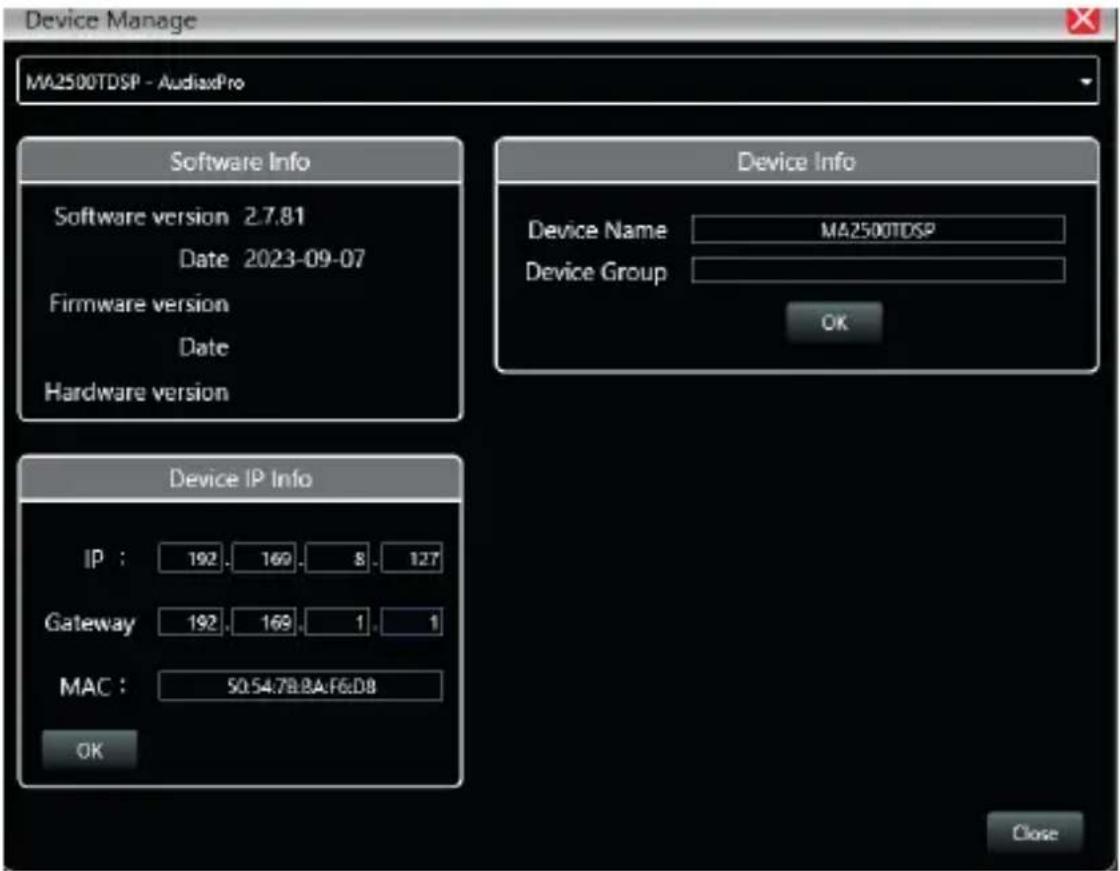
②The device model and LINK ID cannot be changed. The LINK ID is the corresponding ID when the host computer connects to multiple devices.
Input settings
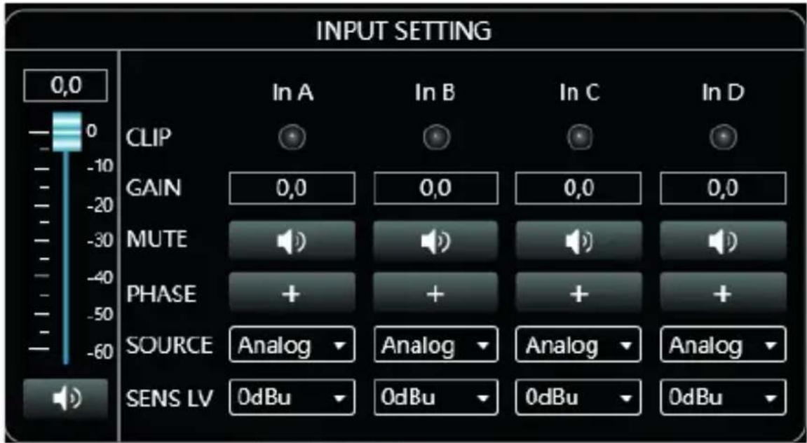
①As shown in the Figure above we have an input volume control potentiometer that can be adjusted by dragging the mouse over the controller, or by assigning a value in the box -10.0 with steps per dB (range -60 to 0.0) icon speaker selects Mute, if activated a red cross will be displayed.
②If the input level is too high, the virtual CLIP LED (INA or INB) will illuminate.
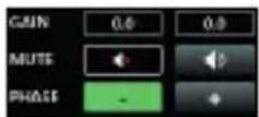
③Adjustment of gain, silence or phase.
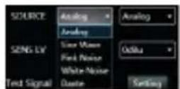
④Select the type of input or pilot noise emitter (Analog, Sine Wave. Pink noise, White noise) for the DSP version, and (Dante, Automix and priority for the Dante version.
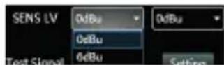
⑤ 0dBu, 6dBu analog signal sensitivity adjustment.
Amplifier status
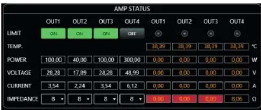
As shown in this figure the output limiter and impedance can be adjusted in this section 16 ohms up to 150w, 8 ohms up to 300W, 4 ohms up to 600W.
SUPERIOR MENU
Archive
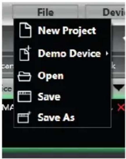
Menu File (Archive)
- New project: delete all information from the panel, to create a new project from scratch.
- Demo device: you can add units in standalone mode, and then transfer them to the network units.
- Open a location where you save your projects.
- Save: save the current project.
- Save as: save the project in a specific location.
Device
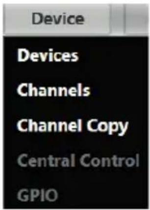
As shown in Figure "Device" Menu:
- Device Management: View or modify software information, device name and device IP address.
- Channel Management: Set the name of each input and output channel.
- Channel Copy: Copy the parameters of the same channel type.
- Code Generator (RS232/485) for the different sending or receiving functions of the unit (presets, control, programs, etc.)
Connection
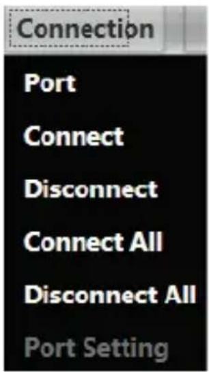
As shown in Figure "Device" Menu:
- Port : Select the type of port to connect the device (COM,USB,TCP).
- Connect: activate the units already connected.
- Disconnet: Disconnect the connected unit.
- Connect All: connect all units.
- Disconnect All: Disconnect all units.
Archive
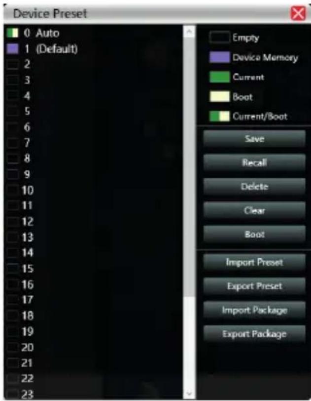
Machine equipment file operation:
- Save: Save the configuration in the selected box.
- Recall: Load the configuration of the selected box.
- Delete: Delete the information in the selected box.
- Clear: Clear the information from all boxes on the unit.
- Boot: Select The selected configuration as the boot configuration every time the unit is turned on, by default.
- Import Preset: Import a Preset file from a location on your PC.
- Export Preset: Export a Preset file from the unit to a specified location on the PC.
- Import File: Import multiple compressed files from your computer
- Export Package: Export the entire set of files on the drive to a specific location on the PC.
System
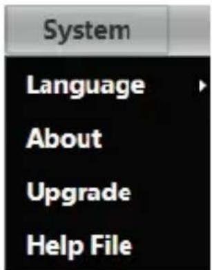
System Menu
- Language: Select from several languages (We are currently working to expand them).
- About: Unit software information, and current driver build and device version information.
- Firmware Update: Update the device firmware.
- Help File: Unit manual.
Scanning
As shown in the following figure 2.7 progress display box, click the "Scan" button to directly scan all devices in the currently set connection mode, and display the scanning progress.
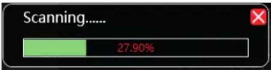
bar
| Scanning..... | Value | | -------------- | ------- | | | 27.90% |Set up
Set the connection mode of the scanning device, click the "Settings" button, and the port connection interface as shown in Figure 2.8 will pop up. Select the corresponding mode and set the corresponding parameters to confirm. If the device port changes, you can click "Refresh" in the lower left corner to update the port list instantly.
Net Link
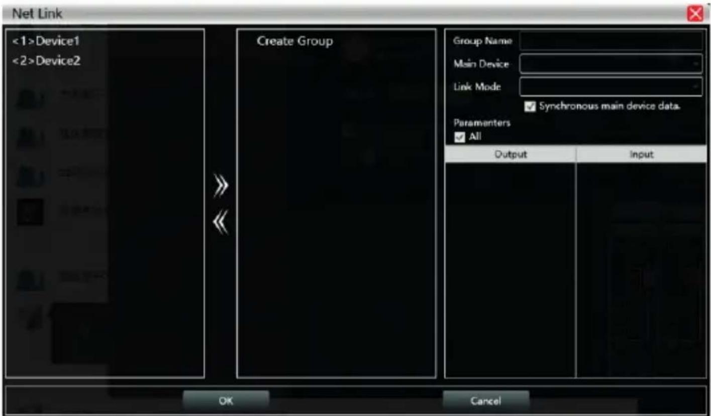
The function of setting multiple device parameters at the same time. Click “Net link”, and the following figure 2.9 Net link interface will pop up. First select the devices that need to be set on the left, then move to the middle, then select the group setting parameters on the right, and finally press "OK", the group function takes effect. You can also correct the network grouping settings with the same operation.
Device List
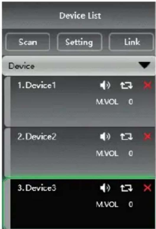
When the software scans or manually adds a simulated device, it automatically adds the corresponding device to the device list, which is convenient for users to interactively operate the required device and to operate multiple devices at the same time.
Local IP address
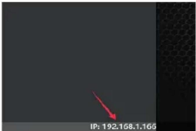
When the software is opened, it will automatically obtain the IP address corresponding to the connection of the PC that is operating the control software, and it will be displayed in the lower left corner of the software to facilitate the management of the device's IP address.
DSP control functions

flowchart
graph LR
    A["HOME"] --> B["INPUT"]
    B --> C["NOISE GATE"]
    C --> D["PEO-X"]
    D --> E["MATRIX/BOX"]
    E --> F["PEO-X"]
    F --> G["DELAY"]
    G --> H["COMP"]
    H --> I["LIMIT"]
    I --> J["OUTPUT"]
In order to facilitate the interaction of different parameters of the device, the software is divided into multiple modules according to the functional order. If the user wants to operate the corresponding module, he can use this module control key to open, close, and locate the module interface. Double-click to turn on / off, and click to locate.
DSP control interface
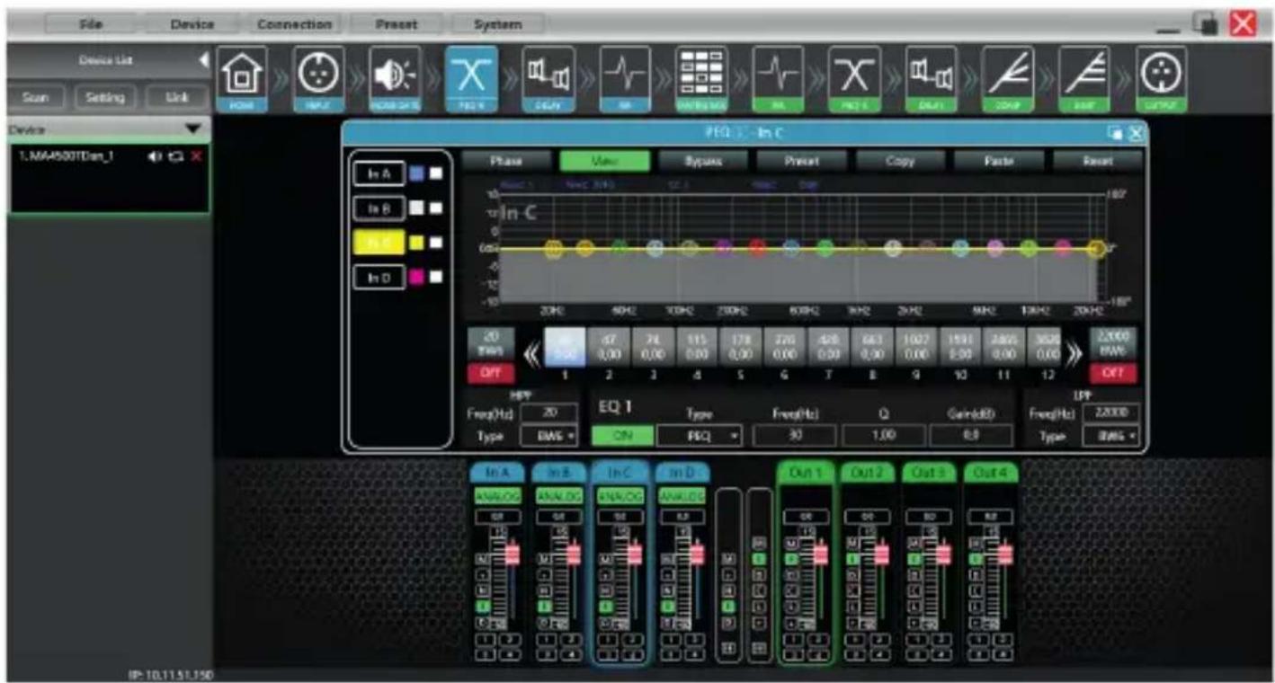
The DSP configuration menu is divided into two sections, from left to right, there are the signal input settings and the signal output controls, with the "Home" button being in the first position to return to the home page of the DSP. same.
Channel interface, input and output
The following interface shows the signal input and output levels, as well as the selection of "input volume, output volume, signal mute, polarity, noise gate, and sending path" in the center column. two cells from left to right that group the functions of both channels as well as the group selector of both sections.
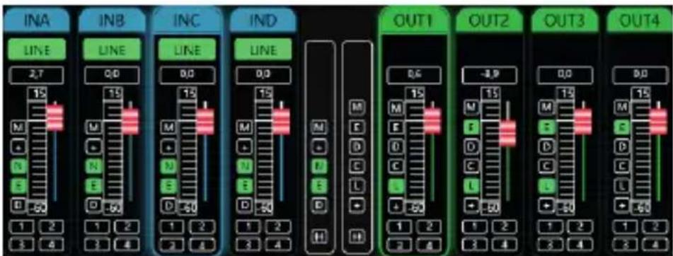
The output section function grouper adds compressor control and signal delay.
INTRODUCTION TO DSP FUNCTIONS
Input module main interface
Double-click the module button and the channel input module shown in the figure below will appear.
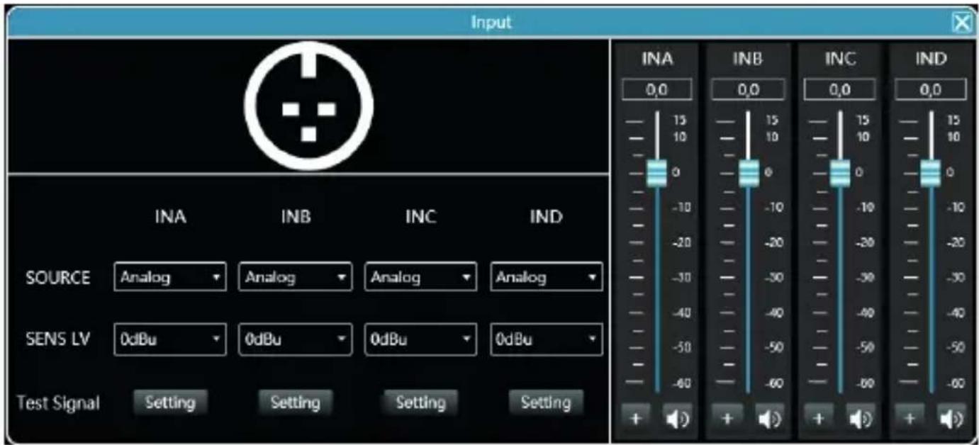
As shown in Figure, you can operate the polarity, mute, and input source sensitivity in the corresponding input channel. In the sensitivity setting, you can choose two gears: 0dBu and 6dBu.
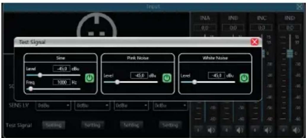
Test signal function
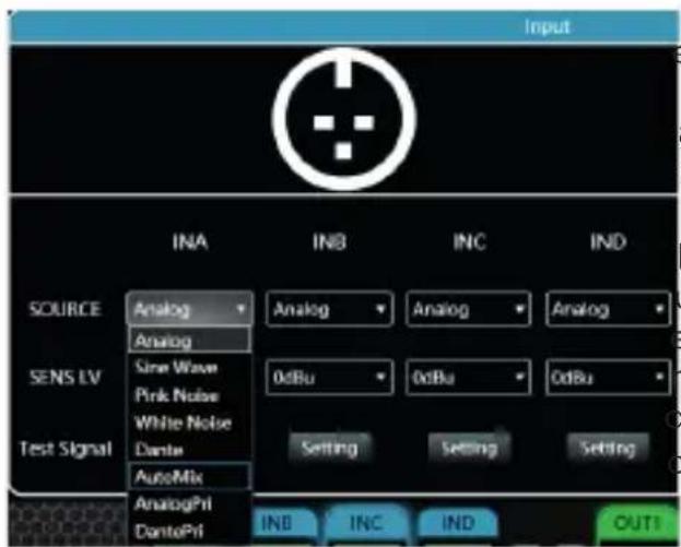
ect the sine wave, pink noise, and white noise in input source, and then set the corresponding ameters to test the channel according to your own requirements in the test signal settings.
The test signal setting, all three test signals can just the gain value. The switch button on the right side of each test signal can control whether the test signal is effective. Green is on and red is off. In addition, the sine wave test signal can also adjust the frequency.
In the MA4500T DSP Dante model, you can also select auto signal mixing or signal priority.
Input noise gate

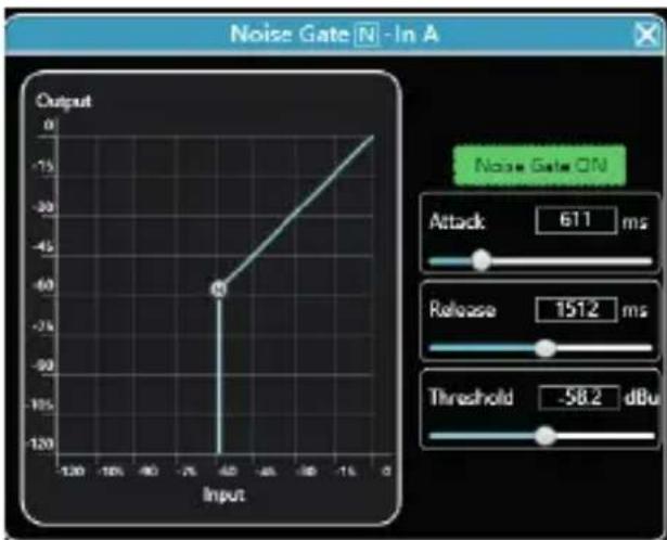
Double-click in the module button to pop up the following figure, Input Noise Gate Setting Module.
line
| Input | Output | |-------|--------| | -40 | -60 |As shown in Figure above, click the noise gate switch Noise Gate ON in the upper right corner to turn on or on the noise gate function of the channel input signal. Green is on and red is off.
The start-up time, release time and start-up level are parameters corresponding to the noise gate function. You can drag the slider or enter the corresponding value value box.
When the noise gate function is turned on, you can drag the points in the graph on the left
to adjust the value obliquely.
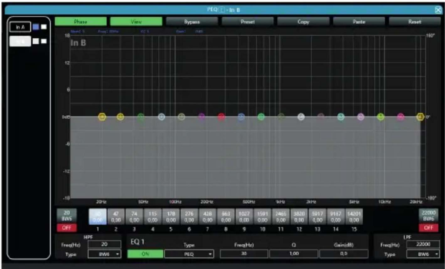
Double-click on the module button, the following figure input equalizer setting
module pops up. The button in the upper right corner of the module can enlarge this module, and the interface display will be clearer after being enlarged.
line
| Frequency | Value | | --------- | ----- | | 20Hz | 0.00 | | 50Hz | 0.00 | | 100Hz | 0.00 | | 200Hz | 0.00 | | 500Hz | 0.00 | | 90Hz | 0.00 | | 2kHz | 0.00 | | 5kHz | 0.00 | | 10kHz | 0.00 | | 20kHz | 0.00 |Function button
As shown in Figure above, the functions of the top buttons are:
Phase curve: Displays the phase curve of the current channel.
Show Control Points: Show or hide all equalization control points.
Full bypass: Turn on or off all equalizer EQs of the current channel at the same time EQ Archive: Save the current equalizer setting parameters to the computer, and recall to overwrite the existing equalizer parameters.
Copy: Copy the current equalizer parameter value and paste it into other input channels.
Paste: Used in combination with the Copy button to paste the copied equalizer parameter values into the current channel.
Reset: Reset the equalizer parameters to the default parameter values.
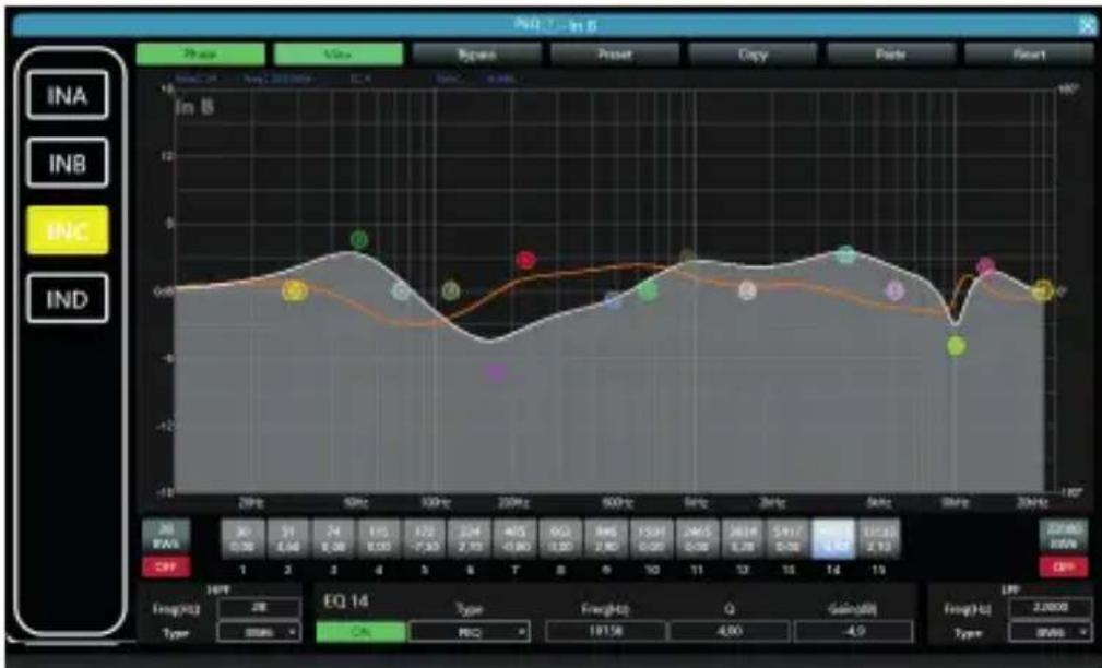
Multi-channel EQ curve display
line
| Time | Value | |------|-------| | 20Hz | 0.00 | | 30Hz | 0.05 | | 40Hz | 0.10 | | 50Hz | -0.15 | | 60Hz | -0.20 | | 70Hz | -0.30 | | 80Hz | -0.40 | | 90Hz | -0.50 | | 100Hz| -0.60 | | 110Hz| -0.70 | | 120Hz| -0.80 | | 130Hz| -0.90 | | 140Hz| -1.00 | | 150Hz| -1.10 | | 160Hz| -1.20 | | 170Hz| -1.30 | | 180Hz| -1.40 | | 190Hz| -1.50 | | 200Hz| -1.60 |As shown in Figure 'Input equalizer setting module' above, the left side is the EQ curve display switch for each channel. When it is turned on, the curve of the corresponding channel will be drawn in the EQ curve chart.
EQ controls
As shown in Figure 'Input equalizer setting module' above, below the curve chart,
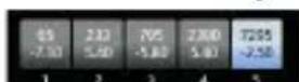
all EQ controls and their detailed values are displayed, which can be
used to locate the position of the controls. Combined with the EQ parameter adjustment items below, each EQ parameter value can be precisely adjusted.
EQ parameter adjustment

As shown in Figure 'Input equalizer setting module' above, below the EQ control is EQ parameter adjustment items, which can precisely control the EQ's switches, type, frequency, Q value, and gain parameters.
EQ archive button
As shown in Figure 'Input equalizer setting module' above, the EQ archive shown in Figure will pop up when you click the EQ Archive button.
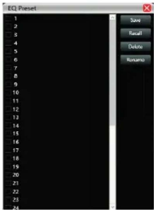
Select the corresponding gear in the gear list on the left, and then click the function button on the right to archive, recall, delete, and rename the equalizer setting parameters.
Entry delay module
Double click the module button to open the input delay setting module interface.
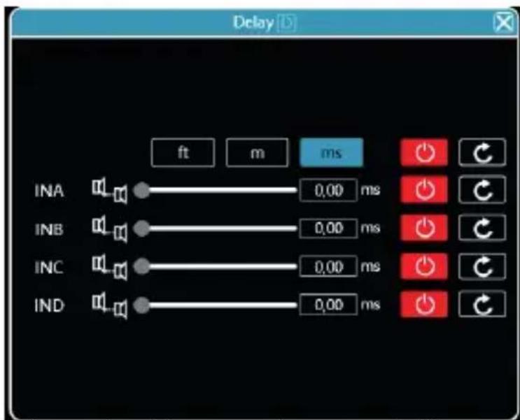
As shown in the figure above, the delay control content of all input channels is listed. Drag the slider to intuitively adjust the delay value of the corresponding channel, or enter the corresponding value in the value box 6.55 mm. This is the delay function switch. Red is off and green is on. The reset button can directly reset the default value of the channel delay.
Input FIR filters:
Due to the power of the DSP built into the unit, the system is equipped with four FIR (Finite Impulse Response) Filter modules. These filters can improve the definition of your audio system as well as better precision in its adjustment.
Press the FIR icon in the entry modules section:
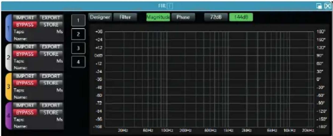
Within the base module, you can edit, create and compare the filters already saved or that you need to design.
If you click on the window expansion icon (top right of the module, next to the closing X).
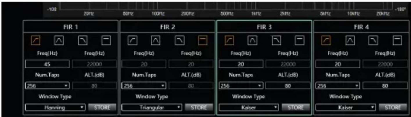
In this section you can select the filter working frequency, the number of samples to be treated and the type of execution window (window type).
Audio matrix

Double-click the module button and the matrix mix configuration module shown in Figure will appear.
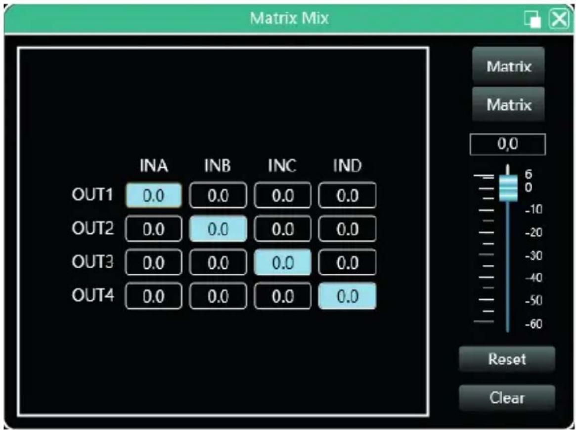
In the following module you can see two blocks, the left block (INA-INB, OUT1, OUT2) indicates the channel selection and volume, in the right block, the level adjustment of the selected channel, the mode selector matrix (Matrix, Bridge, Parallel, Stereo), the level reset button or the Clear function to clear the configuration.
Output equalizer
Double-click the module button to open the input equalizer configuration module interface shown in Figure. The functions and operation methods are the same as the input equalizer.
Output delay
Double-click in the module button to pop up the module interface of Figure Output Delay Setting Module.
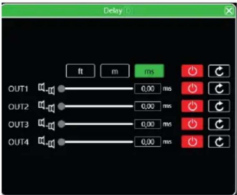
As shown in Figure above, the delay control content of all output channels is listed. Drag the slider to intuitively adjust the delay value of the corresponding channel, or enter the corresponding value in the value box. This is the switch of the delay function. Red is off and Green is on. The reset button can directly reset the default value of the channel delay.
Output compressor
Double-click in the module button to pop up the following figure Output compressor setting module.
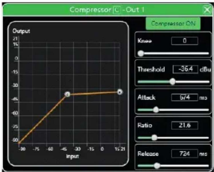
line
| Input | Output | |-------|--------| | -90 | -60 | | -30 | -30 | | 21 | -30 |Output limiter
Double-click 📄 on the module button to pop up the following figure Output Limiter Setting Module.
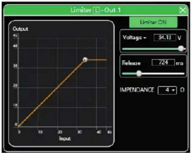
line
| Input | Output | |-------|--------| | 0 | 0 | | 32 | 33 |Output module
Double-click in the module button to pop up the output setting module as shown in Figure Output setting module.
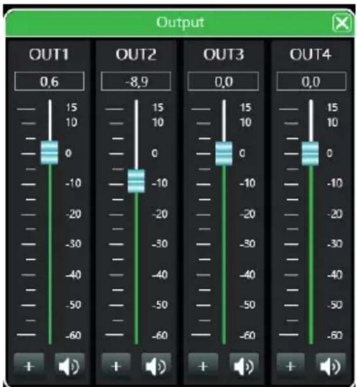
As shown above, you can control the polarity and mute of the corresponding output channel.
Input channel
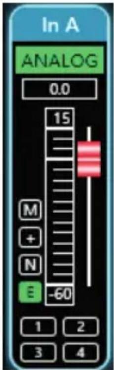
①The input channel interface from top to bottom includes: Channel name, In A Input mode ANALOG, Channel gain, Function buttons, and Channel group joint debugging.
②The Channel name, Input mode, and Channel group joint debugging can only be viewed, and there is no editing function.
③In the Channel gain, you can see the level status of the input channel signal.
④Among the function buttons, from top to bottom are: Mute ⚠, Polarity ⚠, Noise gate ⚠, and Equalizer bypass ⚠. If the mute button is red, it is muted. If the other buttons are green, they are in effect.
⑤Channel group joint tuning shows the default 4 channel joint tuning group. When the background of the corresponding number box turns yellow, it means that this channel has been added to the second group for joint tuning.
⑥The button bar in the middle of the input and output channels is the master switch of the function button corresponding to all input and output channels. It will directly operate all input and output channels simultaneously.
Output channel
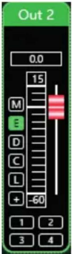
①The output channel interface from top to bottom includes: Channel name Out 2, Channel gain, Function buttons 2, and Channel group joint debugging 1 2 1 4.
②Among them, the Channel name, Digital output status and Channel group joint debugging can only be viewed without editing function. In the channel gain, you can see the level status of the output channel signal. The other two parts (gain value box and gain slider) are for adjusting the gain value of this channel.
③Among the function buttons, from top to bottom are: Mute M Equalizer bypass E, Delay D, Compressor C, Limiter L, and Polarity +. If the Mute button is red, it is muted. If the other buttons are green, they are in effect.
④The channel group joint tuning situation shows the default 4 channel joint tuning group. When the background of the corresponding number box turns yellow, it means that this channel has been added to the second group for joint tuning.
Input channel
Double-click 📄 in the module button to pop up the output setting module as shown in Figure Output setting module.
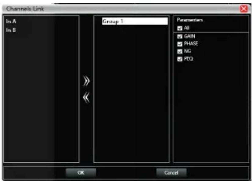
As shown in the figure above, the three lists from left to right are Channel list, Group list, and Parameter list:
The Channel list has listed all the channels that can be tuned. After selecting the
corresponding channels, click the Add button ➞ to move to the Group list. There are already 2 groups in the group list. Select the corresponding group directly, if you add a channel, it will be directly divided into the selected group. To remove, select the channel to be removed, and then click the Remove button ➞ to remove it to the channel list.
The parameter list is a parameter that can be tuned during group link. Ticking indicates that when one channel in the same group is adjusted, the other channels will make the same adjustment at the same time.
Device List
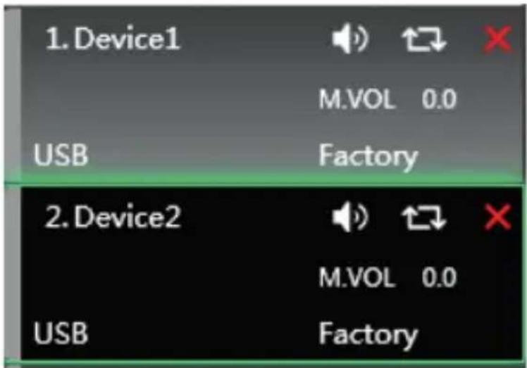
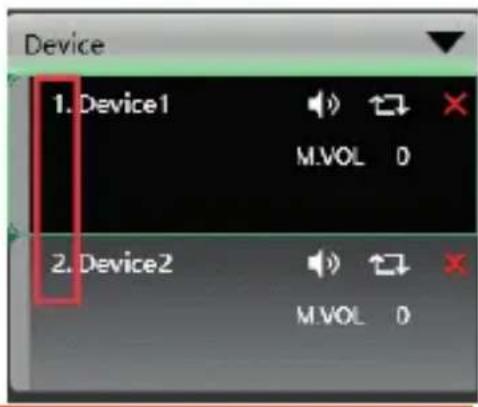
In the figure above, <1> it is the device number on the connection, Device1 it is the device name, Factory it is the factory name (the user cannot modify it). If the connection method is TCP, the network IP address of this device will be displayed in the space to the left of the factory name after connecting. If the connection method is USB, USB is displayed. If the connection method is a serial port, the specific COM port is displayed.

From left to right are the Mute button, Status refresh button and Remove device button. The Mute button can directly control the mute of all input and output channels of the entire device. The Status button refreshes the status of the device instantly. If the device is online, the leftmost position will turn green. The Remove button removes this device directly in the software.
If you need to debug different devices, you can click to select the target device, and it will update to the function page of that device.
Equipment management
Click "Device"-"Device Management" in the menu bar of the main interface of the software, and the device management interface shown in Figure will pop up.
Figure Device Management Interface
As shown above, the device information displayed on the target device management interface can be selected in the device list at the top. The device management interface is divided into the following four blocks:
①Software information: Display the version number and date information of the upper and lower computer of the current device.
② Device information: Display the device name, device group, and factory name information of the current device. To display the factory name, you need to press the hidden shortcut CTRL + ALT + F12. Among them, "device name" and "factory name" can be entered in the new name and click the button to save.
③ Device IP information: If the current device is connected with network information, the device's IP address, gateway, and MAC address will be displayed here. IP and gateway can enter new information and click the OK button to save and restart the device network module. , The newly entered network information will take effect immediately.
④Software Logo: Logo of the software itself.
Channel copy
Click "Device"-"Channel Copy" in the menu bar of the main interface of the software, and the channel copy interface shown in Figure is displayed.
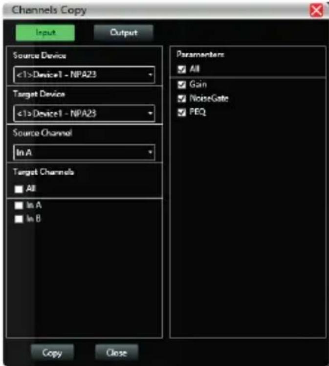
As shown in the figure above, the channel copy is to select the channel parameters of a source device and copy to the target channels of other target devices. Input channels and output channels cannot be copied to each other. The left is the corresponding channel, and the right is the copied parameter. The "Input" and "Output" buttons at the top of the interface can switch the type of channel copied.
Channel name management
Click "Device"-"Channel Management" in the menu bar of the main interface of the software, and the channel name management interface shown in Figure is displayed.
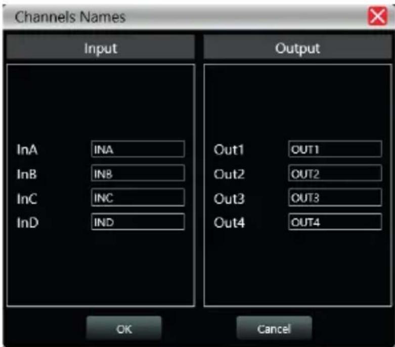
As shown above, after entering the new name of the channel in the corresponding channel, click the OK button to save and update the name of the channel immediately. Note: The length of the channel name is limited to 5 English letters and numbers.
Firmware upgrade
Click "System"-"Firmware Upgrade" in the menu bar of the software main interface, and the firmware upgrade interface shown in Figure 24.1 will pop up.
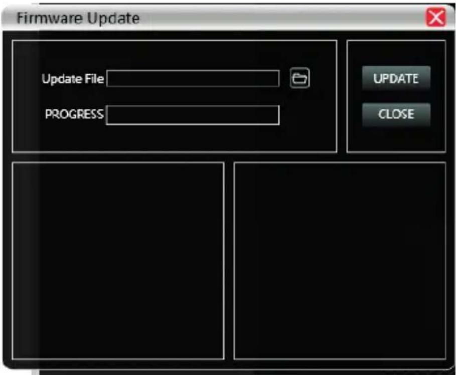
When the lower computer system of the device is updated, after obtaining the upgrade file, you can open the firmware upgrade interface as shown above. Select the corresponding upgrade file in the "Upgrade File" column and click "Start Upgrade" in the upper right corner. The system will automatically transfer the upgrade file to the lower computer for the upgrade operation, and display the operation log in the progress box below. After the upgrade is completed, the lower machine will automatically restart or manually restart the machine to complete the upgrade.
DISPOSAL
Packaging:

-
The packaging can be recycled using standard disposal methods and reintroduced into the reusable material cycle.
-
Please follow the laws and regulations regarding disposal and recycling of packaging in your country.
Device:
natural_image
Simple line drawing of a trash bin with no text or symbols-
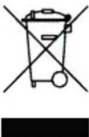
This device is subject to the Waste Electrical and Electronic Equipment (WEEE) Directive of the European Union. Used appliances should not be disposed of with household waste. Used device must be disposed of through an approved disposal company or a municipal disposal facility. Please comply with the applicable regulations in your country.
-
Please follow all the disposal laws and regulations in your country.
-
As a customer, you can obtain information on environmentally-friendly disposal options from the product seller or the appropriate regional authorities.
BIENVENIDO A AUDIBAX
Menu File (Archivo)
Menu Sistema
Enlace de red
- MA4500T DSP / MA4500T DSP Dante
- INDEX / ÍNDICE
- ENGLISH
- ESPAÑOL
- SAFETY INSTRUCTIONS
- GENERAL INFORMATION
- FOR DEVICES DESIGNED TO BE CONNECTED TO THE MAIN POWER SUPPLY:
- IMPORTANT INFORMATION
- PACKAGE CONTENT
- PRODUCT DESCRIPTION
- FEATURES
- FUNCTIONAL STRUCTURE
- INTRODUCTION TO POWER CONTROL
- SOFTWARE INSTALLATION
- Operating environment
- Run PowerControl
- SOFTWARE INTERFACE DESCRIPTION
- INITIAL INTERFACE
- Device settings
- Input settings
- Amplifier status
- SUPERIOR MENU
- Archive
- Menu File (Archive)
- Device
- Connection
- System
- System Menu
- Scanning
- Set up
- Net Link
- Device List
- Local IP address
- DSP control functions
- DSP control interface
- Channel interface, input and output
- INTRODUCTION TO DSP FUNCTIONS
- Input module main interface
- Test signal function
- Input noise gate
- Function button
- Multi-channel EQ curve display
- EQ controls
- EQ parameter adjustment
- EQ archive button
- Entry delay module
- Input FIR filters:
- Audio matrix
- Output equalizer
- Output delay
- Output compressor
- Output limiter
- Output module
- Input channel
- Output channel
- Equipment management
- Figure Device Management Interface
- Channel copy
- Channel name management
- Firmware upgrade
- DISPOSAL
- Packaging:
- Device:
- BIENVENIDO A AUDIBAX
- Menu File (Archivo)
- Menu Sistema
- Enlace de red
Brand : Audibax
Model : MA4500T DSP Dante
Category : Receiver