Zone 120 BT - Receiver Audibax - Free user manual and instructions
Find the device manual for free Zone 120 BT Audibax in PDF.


| Product Type | Audio Receiver |
| Brand | Audibax |
| Model | Zone 120 BT |
| Dimensions (W x H x D) | 43 x 20 x 5 cm |
| Weight | 2.5 kg |
| Power Supply | AC 110-240V, 50/60Hz |
| Power Consumption | 120W |
| Bluetooth Version | 5.0 |
| Bluetooth Range | Up to 30 meters |
| Audio Inputs | RCA, 3.5mm, Bluetooth |
| Audio Outputs | Speaker terminals (1 pair), RCA line out |
| Supported Audio Formats | MP3, WAV, FLAC |
| Frequency Response | 20Hz - 20kHz |
| Signal-to-Noise Ratio | ≥90 dB |
| Total Harmonic Distortion | <0.1% |
| Impedance | 4-8 ohms |
| Cooling | Passive ventilation |
| Material | Metal chassis, plastic front panel |
| Color | Black |
| Included Accessories | Remote control, power cable, user manual |
| Maintenance | Wipe with dry cloth. Keep vents unblocked. |
| Safety | Do not expose to water or heat sources. Use only supplied power cable. |
| Spare Parts & Repairability | Contact authorized service center. No user-serviceable parts. |
Frequently Asked Questions - Zone 120 BT Audibax
User questions about Zone 120 BT Audibax
0 question about this device. Answer the ones you know or ask your own.
Ask a new question about this device
Download the instructions for your Receiver in PDF format for free! Find your manual Zone 120 BT - Audibax and take your electronic device back in hand. On this page are published all the documents necessary for the use of your device. Zone 120 BT by Audibax.
USER MANUAL Zone 120 BT Audibax
| Player | USB | Type | OTG2.0 full-speed controller |
| Connectors | USB 2.0 Type-A | ||
| SD/MMC Connecto rs | Non-self-locking so card slot | ||
| Bluetooth | Version | Bluetooth Ver20+EOR | |
| Max range | 10m (without interference) | ||
| Trans Frequencies | 2402-2480MHz | ||
| Music formats | MP3/WAW/WMA/FLAC (8/16/24bit) | ||
| File system | FAT16 or FAT32 | ||
| FM Section | Tuning range | 87.5MHz to 107.9MHz | |
| Antenna input | 75Ω unbalance d | ||
| Outputs | Low impedance | 4Ω | |
| Constant Voltage impedance | 167Ω-Zone 60BT | ||
| 84Ω-Zone 120BT | |||
| 42Ω-Zone 240BT | |||
| 28Ω-Zone 360BT | |||
| Indicators | LED | Power/Zone/Output | |
| LCO | Player | ||
| Sound | Protect | ||
| Protection | DC-Short Circuit | ||
| Over Healing | |||
| Over Load | |||
| Limiter | |||
| Cooling system | Fan cooled | ||
| Amplifier technology | Class A/B | ||
| Power supply | Master | AC230V-240V/50-60Hz | |
| Standby | DC24v | ||

Zone 120 BT
Zone 240 BT
Zone 360 BT
Please read the manual before using the product

Zone 120BT / Zone 240BT / Zone 360BT
USER'S MANUAL
Index
Introduction....2
System Black Diagram....2
Precautions....2
Safety requirements....2
Caution servicing....3
EC Declaration of Conformity....3
Caution....4
Chapter 1: Pin connections and connectors....4
Connection standards....4
Chapter 2: Front & rear panel....5
Front panel overview....5
Front panel description....5
Rear panel overview....8
Rear panel description....8
Chapter 3: Setting up the system....10
Connection the loudspeakers....11
Connection the audio sources....12
Phantom power....13
To start playing music form MP3....13
To start playing music via Bluetooth 13
Chapter 4: Additional information....14
Technical specifications....14
ATTENTION
- Do not operate the amplifier or disconnect power cable during firmwave update Firmware update takes about 10 seconds
- No files other than firmware in USB storage device or SD card.
- Do not perform this procedure unless firmware update is necessary. Also make sure you read the information supplied with updates before updating the firmware.
Chapter 4
Additional information
Technical specifications
| RMS Output Power1 kdiE.TriD %o | Zone 120BT | 120 Watt | |
| Zone 240BT | 240 Watt | ||
| Zone 360BT | 360 Watt | ||
| Frequency response | 20Hz-20KHz | ||
| Signal to Noise Ratio | >90dB | ||
| THD+N | <0.5% | ||
| Common Mode Rejection | <0.5% | ||
| Crosstalk | >70dB | ||
| Input s | MiCI-2 | Type | 2x Balanced mic / Un e |
| Sensitivity | -50dB | ||
| Connectors | 2xXLR/6.3mmJack combo | ||
| Phantom power | 15VDO | ||
| Priority | Yes | ||
| LINE 1/MIG3 | Type | Balanced mic/line | |
| Sensitivity | -50dB | ||
| Connectors | XLBI6.3mm Jack combo | ||
| Priority | YES | ||
| LINE2-3 | Type | 2x Stereo ling | |
| Sensitivity | -30dB | ||
| Connectors | 2x RCA | ||
| Chime/Fire/TEL | Type | Priority mic input$ | |
| Connectors | Euro terminal block-5.08mm | ||

Zone 120BT / Zone 240BT / Zone 360BT
USER'S MANUAL
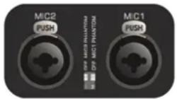
3) Phantom power
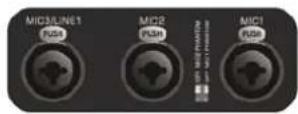
MIC input 1&2 contain the possibility for supplying 15Volts phantom power for powering condenser microphones. Enabling of the phantom power can be done by the switches located between MIC 1&2 connections. Switch 2 will enable phantom power to Mic input 1 while switch 1 enables phantom power to Mic input 2.
4) To start playing music form MP3
Insert a USB storage device or SD/MMC memory card to the slots on front of the device. The MP3 player can play such as MP3WMAWAVFLAC. AAC audio formats When the media is inserted the device will detect automatically and will start playing You can select the playing tracks using the control buttons on front of the device. For switching to settings of another media source, press the M button on front (The variable audio output will switch automatically to this media source)
5) To start playing music via Bluetooth
Adjust the bluetooth antenna to a vertical position then press the M button on front to switch the operation mode to Bluetooth. Turn on the bluetooth on your device(phone computer, ipad, mace or other music playback devices with bluetooth) and search for bluetooth device, you'll find a device named
◀◀ , ▶◀ and ▶◀ "Bluetooth" in the list, select and connect it. Then you can play music on your device, pressing the to control the music track previous, next or pause.
6) Update the player's firmware
New firmware that provides additional features or product improvements will be released as needed. You can download the type MVA of firmware from our website.
Format the USB storage device or SD card for upgrade flirs. Insert a USB storage device or SD card with firmware on the front if the player detects firmware, it will automatically extinguish the LCD screen and start to upgrade the firmware, it will restart about 10 seconds later.
Introduction
Public address amplifiers
The Zone series public address amplifier was developed as an easy to use, flexible solution for multifunctional use
During the development of the Zone series amplifiers, our engineers wanted to achieve four goals:
-Delivering a flexible audio solution to control multiple functions - Easy to use
-Excellent sound quality
-Modern and advanced design
The Zone series amplifiers has 2 stereo unbalanced line level inputs, 1 mono balanced line level inputs, 2 mono balanced line level inputs with phantom power, 4 high impedance 100V mono output zones, 1 low impedance 4ohm mono output zone a link output a telephone signal input, a chime and fire signal input, an 100V emergency input with 24V control, a lossless music player with screen, including FM tuner, the model with a "+BT" version also has bluetooth.
The Zone series amplifiers can be used in commercial applications such as restaurants, hotels, shops, warehouses, professional offices, public buildings.... A simple example: when installed in a shop you could connect a tuner to play your favorite radio station, microphone to make announcements, a telephone pager, and off course the doorbell of the shop.
Precautions
READ FOLLOWINGINSTRUCTIONS FOR YOUR OWN SAFETY
ALWAYS KEEP THESE INSTRUCTIONS NEVER THROW THEM AWAY
ALWAYS HANDLE THIS UNIT WITH CARE
HEED ALL WARNINGS
FOLLOW ALLINSTRUCTIONS
NEVER EXPOSE THIS EQUIPMENT TO RAINMOISTUREANY DRIPPING ORSPLASHING LIQUID. AND NEVER PLACE AN OBJECT FILLED WITH LIQUID ON TOP OF THIS DEVICE

Zone 120BT / Zone 240BT / Zone 360BT
DO NOT PLACE THIS UNIT IN AN ENCLOSED ENVIRONMENT SUCH AS A BOOKSHELF OR CLOSET ENSURE THERE IS ADEQUATE VENTILATION TO COOL THEUNITDO NOTBLOCK THE VENTILATION OPENINGS
DO NOT STICK ANY OBJECTS THROUGH THE VENTILATION OPENINGS
DO NOT INSTALL THIS UNIT NEAR ANY HEAT SOURCES SUCH AS RADIATORS OR OTHER APPARATUS THAT PRODUCE HEAT
DO NOT PLACE THIS UNIT IN ENVIRONMENTS WHICH CONTAIN HIGHLEVELS OF DUST HEATMOISTURE ORVIBRATION
THIS UNIT IS DEVELOPED FOR INDOORUSE ONLYDONOT USEITOUTDOORS
PLACE THE UNIT ON A STABLE BASE OR MOUNTITIN A STABLE RACK
ONLY USE ATTACHMENTS & ACCESSORIES SPECIFIED BY THE MANUFACTURER
UNPLUG THIS APPARATUS DURING LIGHTNING STORMS ORWHEN UNUSED FORLONG PERIODS OF TIME
ONLY CONNECT THIS UNIT TO A MAINS SOCKET OUTLET WITH PROTECTIVE EARTHING CONNECTION

CAUTION-SERVICING
This product contains no user serviceable parts. Refer all servicing to qualified service personnel. Do not perform any servicing (unless you are qualified to)

EC DECLARATION OF CONFORMITY
This product conforms to all the essential requirements and further relevant specifications described in following directives: 2004/108/EC(EMC) and 2006/95/EC(LVD)
WASTE ELECTRICAL AND ELECTRONIC EQUIPMENT(WEEE)
The WEEE marking indicates that this product should not be disposed with regular household waste at the end of its life cycle. This regulation is created to prevent any possible harm to the environment or human health.

This product is developed and manufactured with high quality materials and components which can be recycled and/or reused. Please dispose this product at your local collection point or recycling center for electrical and electronic waste. This will make sure that it will be recycled on an environmentally friendly manner, and will help to protect the environment in which we all live.
flowchart
graph TD
    A["10.2 - 100V ZONE ZONE ZONE ZONE"] --> B["DLTP-JT"]
    B --> C1[" matching transformer "]
    B --> C2[" matching transformer "]
    B --> C3[" matching transformer "]
    B --> C4[" matching transformer "]
    C1 --> D1[" + "]
    C2 --> D2[" + "]
    C3 --> D3[" + "]
    C4 --> D4[" + "]
    D1 --> E1[" + "]
    D2 --> E2[" + "]
    D3 --> E3[" + "]
    D4 --> E4[" + "]
2) Connecting the audio sources
The next step is making the signal input connections. Depending of the type connection and output level of the available audio sources they should be plugged into the matching channel/connection.
Before connecting, turn all the channel input and master volume controls on the front panel of the amplifier fully counter clockwise (to their minimum setting) and put the gain control trimmers on the rear panel in a central position. Then connect all the available sources to their corresponding channels and switch on the power of the amplifier and at the connected audio sources the green light around the power button will illuminate after powering on. The buzzer inside will ring three times and then the output protection relay will be switched on (a click will be heard when this occurs) that mean the amplifier is ready.
Apply a signal to the inputs as it will be used in normal operation circumstances and turn the channel input level control up about 50% Slowly raise the master volume control till a certain level until the desired sound level is achieved. Depending of the output level of the connected music sources the input gain might need adjustment. Adjust these trimmers on the rear panel until the desired level is achieved.
For the best signal to noise ratio, the amplifier should run in normal circumstances with the master level control near maximum position and the peak indicator (0 dB) of the VU meter on front should light occasionally (but not frequently during peak levels. If the signal is too loud or distorted use the input level controls to attenuate as necessary to achieve the desired speaker level.

Zone 120BT / Zone 240BT / Zone 360BT
1) Connecting the loudspeakers
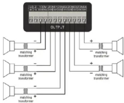
The loudspeakers should be connected to the euro terminal block connectors on the back panel of the device. First the decision should be made which kind of loudspeakers will be used between low impedance (4 Ohm) or constant voltage(100V/70V/) depending on the project requirements. It is only possible to use one (either constant voltage or low impedance) of both options at a time
For operating using the low impedance (4 ohm) output any loudspeaker with a minimum impedance load of 4 ohms (that is 4 ohms or greater) can be used.
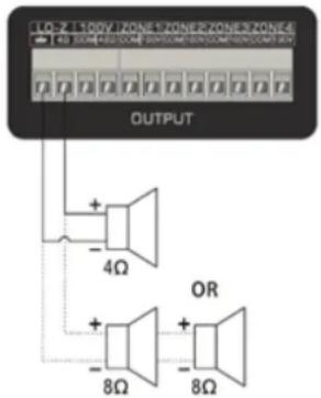
Example diagram low impedance connections
For operating using constant voltage (100V/70V/...) audio distribution systems, the positive output should be connected to the positive terminal of the loudspeakers, while the negative terminal of the speaker should be connected to the COM (ground) terminal of the amplifier.

ATTENTION
THE TOTAL IMPEDANCE OF ALL CONNECTED SPEAKERS MUST BE GREATER THAN THE RATED IMPEDANCE OF THE AMPLIFIER
CAUTION
The symbols shown are internationally recognized symbols that warn about protentional hazards of electrical products. The lightning flash with arrow point in an equilateral triangle means that the unit contains dangerous voltages. The exclamation point in an equilateral triangle indicates that it is necessary for the user to refer to the user manual.

These symbols warn that there are no user serviceable parts inside the unit. Do not open the unit Do not attempt to service the unit yourself. Refer all servicing to qualified personnel. Opening the chassis for any reason will void the manufacturer's warranty. Do not get the unit wet. If liquid is spilled on the unit shut it off immediately and take it to a dealer for service. Disconnect the unit during storms to prevent damage.
Chapter 1
Pin connections and connectors
CONNECTION STANDARDS
The in and output connections for our audio equipment are performed corresponding to international wiring standards for professional audio equipment.
RCA(Cinch):
For unbalanced line input
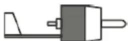
Tip: Signal Sleeve: Ground
White: Left Red: Right
XLR:
For balanced signal input connections
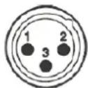
Pin 1: Ground
Pln 2: Signal+
Pin 3: Signal-

Zone 120BT / Zone 240BT / Zone 360BT
USER'S MANUAL
6.3mm (1/4) balanced Jack:
For balanced line in & output connections.
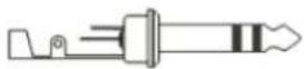
Tlp: Signal+ Ring: Signal- Sleeve: Ground
6.3 mm (1/4") unbalanced Jack:
For unbalanced line in & output
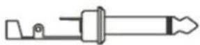
Tip: Signal Sleeve: Ground
Chapter 2
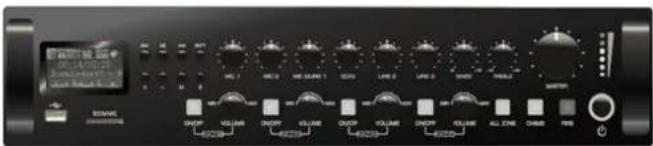
Front & rear panel Front panel overview
Front panel description
The front panel for Zone series amplifiers is identical and enables you to control the level for every input and the overall output volume. A two band tone control is provided for the main output, allowing adjustment of the overall system frequency response while zone (output) switches allows enabling/disabling of the different speaker zone outputs each zone output has a separate volume control. The music player can play such as MP3,WMA,WAV,FLAC AAC and other formats of digital music the model with "+BT" also lets you can play music from your smartphone or computer via bluetooth 2.0.
Input level controls
Using the input level controls, the individual level for each connected input can be set. This way, multiple inputs can be mixed with each other between zero and maximum level.
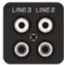
Unbalanced line Inputs 2 & 3 (RCA Jack):
Line inputs 2 and 3 are implemented using RCA jack connections it can be made a stereo line input red for right channel while for left channel.
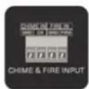
Chlme & Fire Inputs (Terminal block):
Chime & Fire inputs can be connected to any external source, such as call station, signal matrix, fire alarm system. These channels have priority over other inputs.
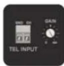
Tel Input (Terminal block):
The amplifier can be connected to any business telecom system using the tel input, allowing announcements to be made from any handset. It is a line level input with priority to be connected to the line output of the telecom system. Unbalanced input connections should be made to the 'CH' (Hot or Signal) and GND (Ground) terminals.
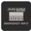
Emergency input (Terminal block):
The amplifier can be connected to any100Vconstantvoltage amplifier output of alarm system with DC 24V remote control using the emergency input. When the DC 24V is input the amplifier will switch the all connected speakers (just constant voltage output) to the alarm input.
Chapter 3
Setting up the system
ATTENTION
Make sure the power of the device is turned OFF before any connections or wiring adjustments are made. Disregarding this rule can lead to permanent damage of the equipment.

Zone 120BT / Zone 240BT / Zone 360BT
USER'S MANUAL
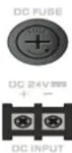
DC Power Inlet:
The main DC power supply (24V) has to be applied to the connector on the left of the AC power inlet. This is a standby power inlet to connect a24V battery. A fuse holder with main fuse is located on the top of the DC power inlet. When replace the fuse make sure the replacement matches the specifications of the original fuse.

WARNING
DC POWER AND AC POWER CANNOT BE USED TOGETHER, THIS WILL DAMAGE THE EQUIPMENT
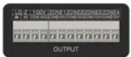
Loudspeaker output connections (Terminal block connectors)
Output connections for both low impedance and constant voltage distributed audio systems are provided. The low impedance loudspeaker and 100V constant voltage output share a 4-PIN terminal block, the two on the left are used to connect low impedance speakers the two on the right are used to connect high impedance (just 100V constant voltage) speakers. While different zone (1-4) outputs are provided on a8-pin terminal block connector More information about loudspeaker output connections is described in a further chapter of this instruction manual.
Link out connections (RCA jack connectors):
These connections can be used when expanding your system by adding a second amplifier in your system. Connect LINE2 or LINE3 input of the second amplifier with the OUT of the master amplifier in your setup.
Balanced line1/mlc Inputs12&3(combination63mmJack&XLR):
Channels1, 2 & 3 are implemented using combination connectors accepting both XLR and 6.3 mm jack plugs. Both inputs will mute all other channels when a signal is present on the connected microphones / inputs / Mic input 1 & 2 can be used for capacitive microphones phantom power switches enable 24Vots phantom power supply for 12V-48V capacitive microphone. Switch 2 will enable phantom power to Mic input 1 while switch 1 enables phantom power to Mic input 2.
Chlme:
When the chime button is pressed the selected chime tone as pre-announcement for paging will be played once.
Fire:
When the fire button is pressed the fire alarm goes through the loop until the fire button is pressed again.
Two band tone control:
Using the bass and treble rotary dials, the overall system frequency response can be adjusted within a range of +12dB. The level will be increased while clockwise rotating, while counter-clockwise will result in a level decrease. In center position, both dials are set to neutral level.
Microphone echo control:
Articulated echo effect suitable for microphone channel
Master volume control:
Using the master volume control the overall system volume will be adjusted in a range between minimum and maximum level
Digital Music player:
This is an AI-In-One Digital audio source device accommodates three different kinds of audio sources into one single device. It including a lossless MP3playerFM tuner Bluetooth (+BT model only), the MP3 player can play such as MP3,WMA,WAV,FLAC,AAC audio formats on the front side is a graphic LCD display screen, an USB slot a SD/MMC memory card slot and 8 control buttons provided.
Button Function

Press: Turn on the player
Press & Hold: Turn off the player

Switch the operation mode between USBSD/MMC Bluetooth

Zone 120BT / Zone 240BT / Zone 360BT
| Press: Started and paused for track when in USB/SD/MMC/Bluetooth ModePress & Hold: Automatically scanning FM radio, store it when in FM tuner Mode | |
| Previous track when in USB/SD/MMC/Bluetooth Mode Previous stored FM radio station when in FM tuner Mode | |
| Next track when in USB/SD/MMC/Bluetooth Mode Next stored FM radio station when in FM tuner Mode | |
| + | Increase player volume |
| - | Reduce player volume |
| RPT | Switch the repeat mode between Repeat One, Repeat Folder, Repeat All and Repeat Off |
USB connection port &SD/MMC card slot:
An USB storage device and/or an SD/MMC memory card can be inserted to these slots. Tracks stored on here can be played through the player and it will automatically start to play when the medium is inserted.

WARNING
DO NOT USE USB PORT TO CHARGE OTHER DEVICES, THIS WILL DAMAGE THE EQUIPMENT
LED Indicators:
The current system operation is indicated on the 6-digit LED bar graph. The LED's monitor the current output eve within a range of -18 dB and 0 dB while the upper LED (red) illuminates when the output is clipping you need to reduce the channel or master volume.
Zone 1-4(output)switches:
The different connected loudspeaker lines (1-4) can be switched on and off by pressing the switches with the corresponding numbers when the zone (1-4) is enabled the green light on the corresponding switch will be illuminated. When the 'All switch is pressed, all zone (1-4) outputs will be enabled
Zone 1-4 (output) level control:
The output level of different zone (1-4) can be adjust within a range of -1.5dB and 0dB by the band switches with the corresponding numbers.
Power switch:
The device can be switched ON and Off using the power switch. When the device is switched ON, the green light around the power button will illuminate. After powering on the buzzer inside will ring three times and then the output protection relay will be switched on (a click will be heard when this occurs) that mean the amplifier is ready.
Rear Panel Overview

Rear panel description
The rear panel for amplifiers is identical and contains all connection and configuration controls (the model without "+BT" has no bluetooth antenna). Configuration controls include the settings which should be made once when setting up the system and doesn't have to be changed by the user afterwards.
AC Power Inlet:
The main AC power supply (230\~240VAC/50\~60 Hz) has to be applied to this AC power inlet. The connection is made by an IEC C14 power connector A fuse holder with main fuse is located on the right of the AC power inlet. When replace the fuse make sure the replacement matches the specifications of the original fuse.
FM antenna:
When using an FM radio, pull out the FM antenna to ensure a good FM reception.
Bluetooth antenna:
When connecting the bluetooth adjust the bluetooth antenna to a vertical position to ensure a good wireless signals and longer distance.
**Only the model with '+BT has a bluetooth antenna**
Example diagram low impedance connections
- Index
- ATTENTION
- Chapter 4
- 3) Phantom power
- 4) To start playing music form MP3
- 5) To start playing music via Bluetooth
- 6) Update the player's firmware
- Introduction
- Precautions
- READ FOLLOWINGINSTRUCTIONS FOR YOUR OWN SAFETY
- CAUTION-SERVICING
- EC DECLARATION OF CONFORMITY
- WASTE ELECTRICAL AND ELECTRONIC EQUIPMENT(WEEE)
- 1) Connecting the loudspeakers
- Example diagram low impedance connections
- CAUTION
- Chapter 1
- CONNECTION STANDARDS
- RCA(Cinch):
- XLR:
- 6.3mm (1/4) balanced Jack:
- mm (1/4") unbalanced Jack:
- Chapter 2
- Front panel description
- Input level controls
- Unbalanced line Inputs 2 & 3 (RCA Jack):
- Chlme & Fire Inputs (Terminal block):
- Tel Input (Terminal block):
- Emergency input (Terminal block):
- Chapter 3
- Setting up the system
- Zone 120BT / Zone 240BT / Zone 360BT
- DC Power Inlet:
- WARNING
- Loudspeaker output connections (Terminal block connectors)
- Link out connections (RCA jack connectors):
- Balanced line1/mlc Inputs12&3(combination63mmJack&XLR):
- Chlme:
- Fire:
- Two band tone control:
- Microphone echo control:
- Master volume control:
- Digital Music player:
- Button Function
- USB connection port &SD/MMC card slot:
- LED Indicators:
- Zone 1-4(output)switches:
- Zone 1-4 (output) level control:
- Power switch:
- Rear panel description
- AC Power Inlet:
- FM antenna:
- Bluetooth antenna:
Brand : Audibax
Model : Zone 120 BT
Category : Receiver