609-208 - Bike rack Hamron - Free user manual and instructions
Find the device manual for free 609-208 Hamron in PDF.


| Product Type | Hitch-mounted bike rack |
| Brand | Hamron |
| Model | 609-208 |
| Weight | 18.5 kg |
| Maximum Load Capacity | 60 kg |
| Number of Bicycles | Up to 4 |
| Mounting Type | Tow bar (ball hitch) |
| Tilt Function | Yes, for boot access |
| Maximum Speed | 120 km/h (75 mph) |
| Wheel Straps | Included (8 pieces) |
| Frame Clamps | Included (4 pieces) |
| Locking Mechanism | Yes, hitch lock |
| Compatible Tow Bar Rating | Min. 60 kg (ST 52-3 or GGG 52) |
| Material | Steel / Aluminum |
| Maintenance | Clean with wet towel or industrial alcohol; lubricate screws with rust-proof oil |
| License Plate Holder | Required (not included) |
| Manufacturer | Jula AB, Box 363, 532 24 SKARA, Sweden |
Frequently Asked Questions - 609-208 Hamron
User questions about 609-208 Hamron
0 question about this device. Answer the ones you know or ask your own.
Ask a new question about this device
Download the instructions for your Bike rack in PDF format for free! Find your manual 609-208 - Hamron and take your electronic device back in hand. On this page are published all the documents necessary for the use of your device. 609-208 by Hamron.
USER MANUAL 609-208 Hamron
EN User instructions for bicycle carrier
Värna om miljön!
Care for the environment!
Must not be discarded with household waste! This product contains electrical or electronic components that should be recycled. Leave the product for recycling at the designated station e.g. the local authority's recycling station.
SE - Bruksanvisning i original
EN - Operating instructions (Translation of the original instructions)
Jula reserves the right to make changes. In the event of problems, please contact our service department. www.jula.com
Tillverkare/ Produsent / Produenci/ Manufacturer
Jula AB, Box 363, 532 24 SKARA
Importör/ Importør/ Importer/ Importer
Date of production: 2016-02-22
© Jula AB
SVENSKA....4
SÄKERHETSANVISNINGAR....4
BESKRIVNING 5
Delarnas placering....6
Montering av plattformen på dragkroken 11
Delenes plassering.... 17
SAFETY INSTRUCTIONS....37
DESCRIPTION 38
Position of the parts....39
Fitting the rack to the tow bar 44
Fitting bicycles to the rack 46
Attach the bicycles to the rack using a strap 47
Opening the boot....47
SÄKERHETSANVISNINGAR


| Del | ||||
| Antal | 2444 |

| Del |  |  |  |  | 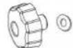 |  |  |  |  | |
| Antal 1 | 2 2 2 2 2 4 4 | 42 |
MONTERING AV PLATTFORMEN PÅ DRAGKROKEN

Håll dragkroken ren



ÖPPNING AV BAGAGELUCKA


Avstanden kan tilpasses til størrelsen på sykkelen
| Del |  |  | 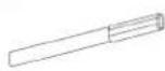 |  | [30T4] |  |
| Antal | 18122 | 2 |
| Del | |
| Antall | 8 |

| Del | ||||
| Antall | 2 4 4 4 |

| Del |  |  |  |  |  |  |  |  | [BYTC] | |
| Antall 1 | 2 2 2 2 2 4 4 42 |
MONTERING AV STATIVET PÅ HENGERFESTET

Hold hengerfestet rent





OTWIERANIE BAGAŻNIKA SAMOCHODU
Read the operating instructions carefully before use!
Please retain for future reference.
Strictly comply with the following safety recommendations when assembling and using this bike carrier:
Note: carefully read all these instructions before beginning to assemble the bike carrier! Comply with the safety recommendations in particular!
- Warning: check the vehicle's tolerated axial load, it must not be exceeded when the bikes are loaded! The tare weight of the bike carrier is 18.5kg!
-
Warning: check the maximum bearing load tolerated by the tow bar attachment.
-
Maximum bearing load>60kg: in this case, 4 bike weighing up to 60kg can be transported!
- Note: the vehicle must be equipped with a type-approved tow hook with a maximum bearing load of at least 60 kg-must be at least type ST 52-3 or GGG 52.
- Note: when assembled, the bike carrier must be equipped with a license plate (the vehicle's license plate remains hidden).
• Technical safety when driving
- Driving speed: never drive faster than the speed prescribed by the Highway Code. Regardless this, you should never exceed a cruising speed of 120 kph when transporting bikes on this bike carrier.
- Opening mechanism: Warning: always make sure that the opening mechanism is closed and fastened.
-
Technical safety when driving Braking, accelerating, driving round bends:
-
Do not brake or accelerate sharply!
- Do not make sharp turns! Make sure the speed is under 40 km / h .
- Make sure the speed is under 40 km / h when in bad situation on the road.
- Inspection of the bike carrier: after having assembled the bike carrier for the first time, check all the fastening mechanisms on it(screws, straps, nuts) after having driven for a short way.
-
Afterthis, these fastening mechanisms must be checked again at regular intervals (more often if the roads are in bad condition).
-
Warning: when the bike carrier is fitted on to the vehicle's tow hook, switch off the engine, turn the ignition key to the off position and apply the hand brake!
- Back up and parking: When the bike carrier is mounted, the total width of the vehicle increased. The same bikes can increase the width and the total height of the vehicle. Be careful in backward motion.
- To ensure the duty life of the products, use a wet towel or industrial alcohol to wipe up after use. For the screws, daub with lubricating oil or rust-proof oil and store in a dry area. When washing vehicle, please take the carrier off. Avoid corrosive solvents including cleaning solvents.
- We reserve the right to improve product appearance and design without notice. In case of discrepancies, defer to actual product.
DESCRIPTION
| Part Quantity Article Part Quantity Article | |||||
| 1 1 11 2 |  |  | |||
| 2 8 12 2 | 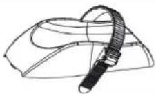 |  | |||
| 3 8 13 4 |  |  | |||
| 4 2 14 2 | 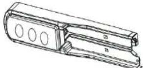 | 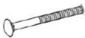 | |||
| 5 8 15 2 |  |  | |||
| 6 10 16 2 |  | 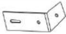 | |||
| 7 4 17 2 |  |  | |||
| 8 | 1 |  | 18 2 |  | |
| 9 2 19 1 |  | 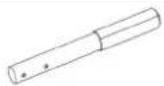 | |||
| 10 | 2 |  | |||
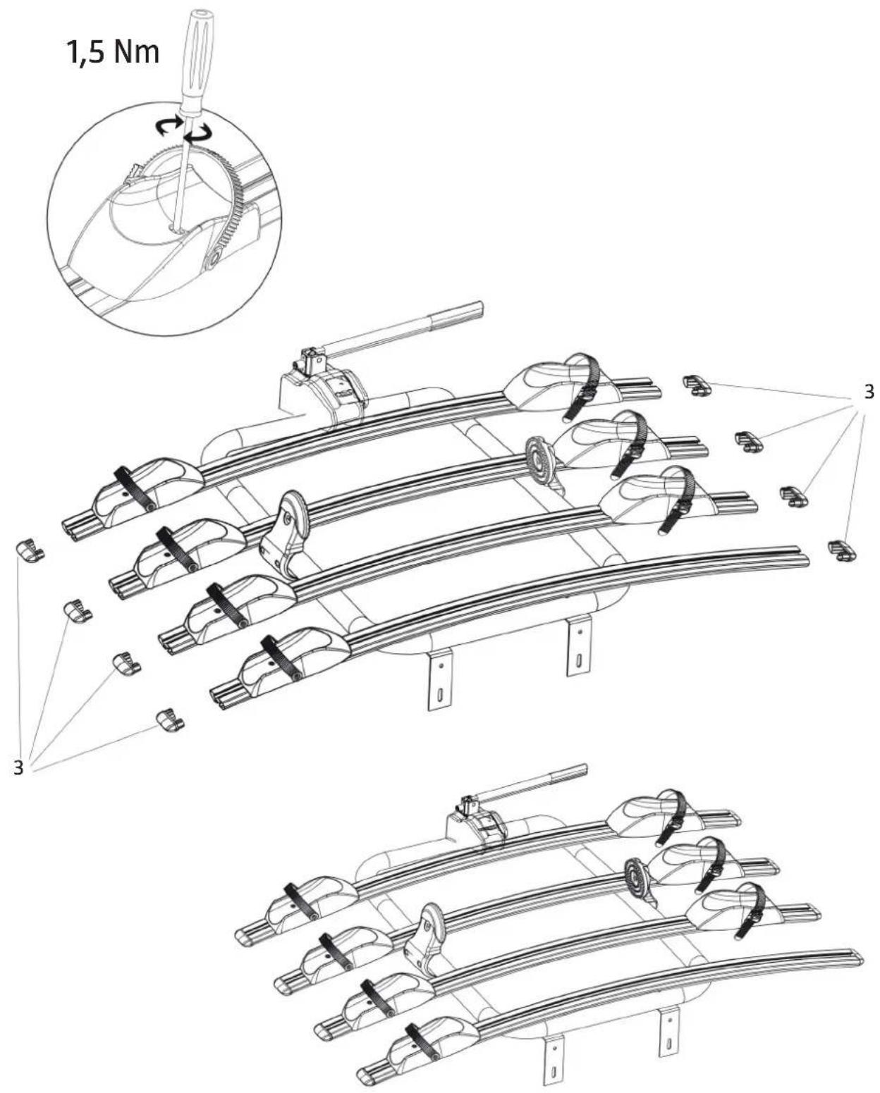
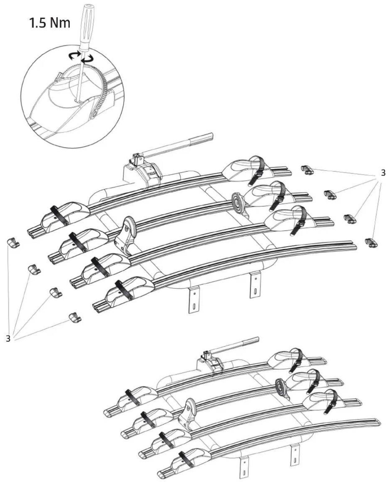
POSITION OF THE PARTS
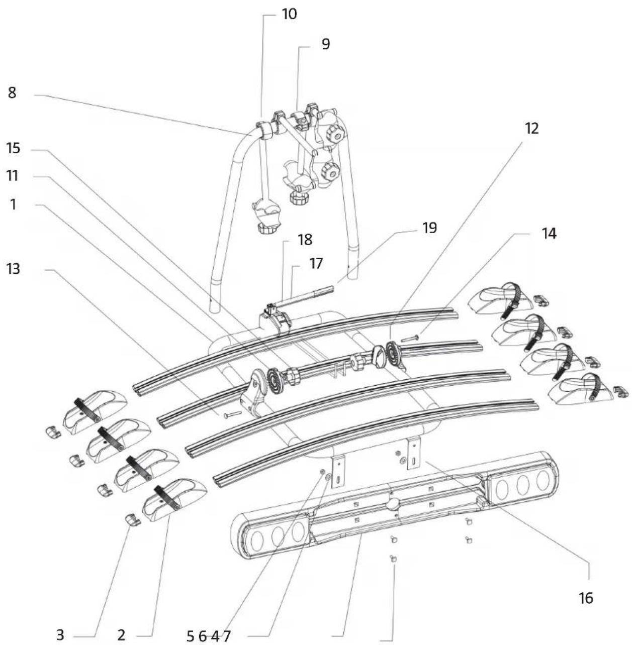


The distance can be adjusted according to the size of the bicycle
| Part |  |  |  |  |  | |
| Quantity | 18122 | 2 |
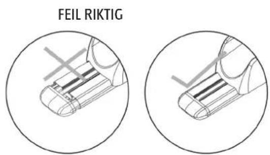
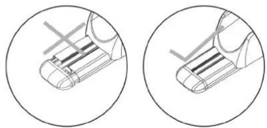
INCORRECT CORRECT
| Part |  |
| Quantity | 8 |

| Part |  |  |  |  |
| Quantity | 2444 |

| Part |  |  |  |  |  |  |  | [6026] |  | |
| Quantity | 1 2 2 2 | 2 2 4 4 42 |
FITTING THE RACK TO THE TOW BAR

Keep the tow bar clean
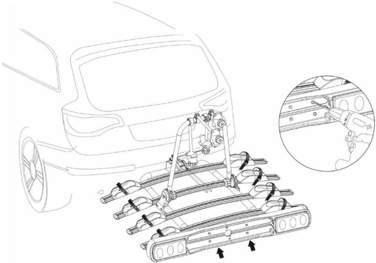


The hitch bicycle rack can be locked once fitted.
FITTING BICYCLES TO THE RACK
Place the bicycle into the wheel holders. Tighten the clamp around the bicycle's frame (Fig. E). The bicycles must be mounted in opposite directions to each other.
Fasten the wheel straps (Fig. D).

ATTACH THE BICYCLES TO THE RACK USING A STRAP



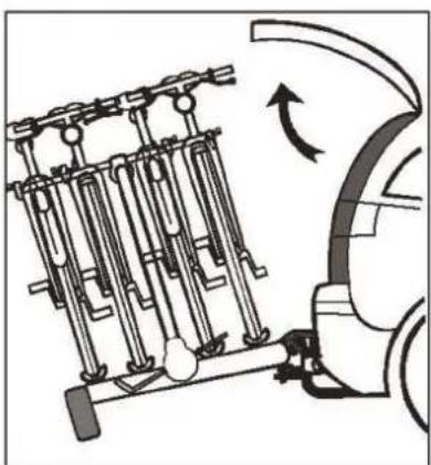
OPENING THE BOOT
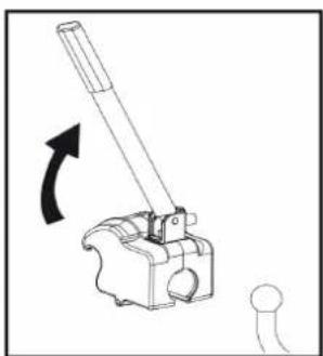
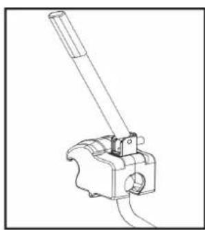
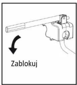
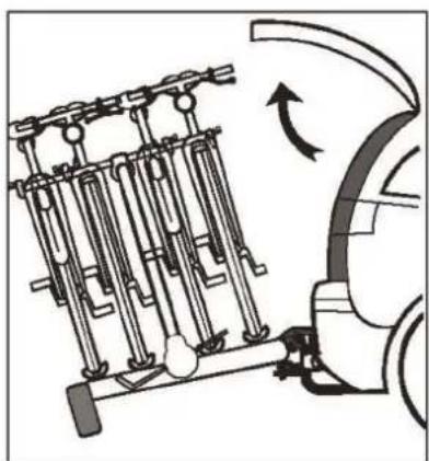
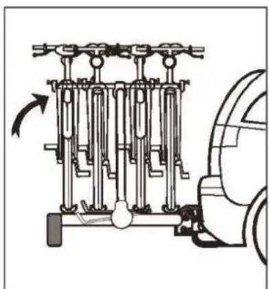
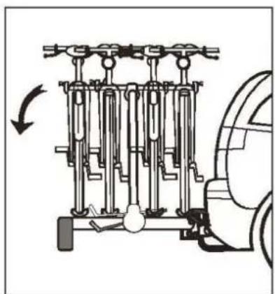
Hold the hitch bicycle rack with one hand, and pull the tilt handle with the other hand. Tilt the hitch bicycle rack downwards until it reaches its lowest position or is resting on the ground. The boot can now be opened. Remember to tilt the rack back up again before driving.
- VÄRNA OM MILJÖN
- CARE FOR THE ENVIRONMENT
- SVENSKA....4
- SÄKERHETSANVISNINGAR....4
- BESKRIVNING 5
- SAFETY INSTRUCTIONS....37
- DESCRIPTION 38
- SÄKERHETSANVISNINGAR
- MONTERING AV PLATTFORMEN PÅ DRAGKROKEN
- ÖPPNING AV BAGAGELUCKA
- MONTERING AV STATIVET PÅ HENGERFESTET
- OTWIERANIE BAGAŻNIKA SAMOCHODU
- READ THE OPERATING INSTRUCTIONS CAREFULLY BEFORE USE
- DESCRIPTION
- POSITION OF THE PARTS
- FITTING THE RACK TO THE TOW BAR
- FITTING BICYCLES TO THE RACK
- ATTACH THE BICYCLES TO THE RACK USING A STRAP
- OPENING THE BOOT
Brand : Hamron
Model : 609-208
Category : Bike rack