LS1440 - Scie à onglet MAKITA - Notice d'utilisation et mode d'emploi gratuit
Retrouvez gratuitement la notice de l'appareil LS1440 MAKITA au format PDF.

| Type de produit | Scie à onglet |
| Marque | MAKITA |
| Modèle | LS1440 |
| Diamètre de lame | 355 mm (14") |
| Alésage de lame | 25 mm (31/32") ou 25,4 mm (1") |
| Vitesse à vide | 3 200 tr/min |
| Capacité de coupe max (H x L) à 0° | 122 mm x 152 mm |
| Capacité de coupe max (H x L) à 45° | 122 mm x 115 mm |
| Angle d'onglet max | Gauche 45°, droite 45° |
| Dimensions (L x l x H) | 530 mm x 440 mm x 610 mm |
| Poids net | 30 kg |
| Alimentation électrique | 120 V, 60 Hz (secteur) |
| Frein électrique | Oui |
| Protège-lame | Automatique à ressort |
| Verrouillage de broche | Oui |
| Sac à poussière | Inclus |
| Étau horizontal | Oui, réversible |
| Sécurité | Verrou de gâchette, arrêt de sécurité |
| Entretien | Nettoyer le protège-lame, lubrifier les parties coulissantes |
| Pièces de rechange | Charbons, flasques, vis de réglage |
| Garantie | 1 an (pièces et main-d'œuvre) |
FOIRE AUX QUESTIONS - LS1440 MAKITA
Questions des utilisateurs sur LS1440 MAKITA
0 question sur cet appareil. Repondez a celles que vous connaissez ou posez la votre.
Poser une nouvelle question sur cet appareil
Téléchargez la notice de votre Scie à onglet au format PDF gratuitement ! Retrouvez votre notice LS1440 - MAKITA et reprennez votre appareil électronique en main. Sur cette page sont publiés tous les documents nécessaires à l'utilisation de votre appareil LS1440 de la marque MAKITA.
MODE D'EMPLOI LS1440 MAKITA
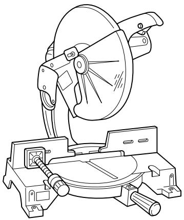
Miter Saw
Equipped with Electric Blade Brake
355 mm (14")
MODEL LS1440
002146

INSTRUCTION MANUAL
WARNING:
For your personal safety, READ and UNDERSTAND before using.
SAVE THESE INSTRUCTIONS FOR FUTURE REFERENCE.
SPECIFICATIONS
Blade diameter 355 mm (14")
Hole diameter 25 mm (31/32") and 25.4 mm (1")
Max. Miter angle Left 45^ ,Right 45^
Max. Cutting capacities (H x W)
| Miter angle | |
| 0° | 45° (left and right) |
| 122 mm x 152 mm (4-3/4” x 6”) | 122 mm x 115 mm (4-3/4” x 4-1/2”) |
No load speed (RPM) 3,200/min.
Dimensions (L x W x H) 530 mm x 440 mm x 610 mm (21" x 17-1/4" x 24")
Net weight 30 kg (66 lbs)
- Manufacturer reserves the right to change specifications without notice.
- Specifications may differ from country to country.
For Your Own Safety Read Instruction Manual Before Operating Tool
Save it for future reference
GENERAL SAFETY PRECAUTIONS
USA007-1
(For All Tools)
- KNOW YOUR POWER TOOL. Read the owner's manual carefully. Learn the tool's applications and limitations, as well as the specific potential hazards peculiar to it.
- KEEP GUARDS IN PLACE and in working order.
- REMOVE ADJUSTING KEYS AND WRENCHES. Form habit of checking to see that keys and adjusting wrenches are removed from tool before turning it on.
-
KEEP WORK AREA CLEAN. Cluttered areas and benches invite accidents.
-
DON'T USE IN DANGEROUS ENVIRONMENT. Don't use power tools in damp or wet locations, or expose them to rain. Keep work area well lighted. Don't use tool in presence of flammable liquids or gases.
- KEEP CHILDREN AWAY. All visitors should be kept safe distance from work area.
-
MAKE WORKSHOP KID PROOF with padlocks, master switches, or by removing starter keys.
-
DON'T FORCE TOOL. It will do the job better and safer at the rate for which it was designed.
- USE RIGHT TOOL. Don't force tool or attachment to do a job for which it was not designed.
- WEAR PROPER APPAREL. Do not wear loose clothing, gloves, neckties, rings, bracelets, or other jewelry which may get caught in moving parts. Nonslip footwear is recommended. Wear protective hair covering to contain long hair.
- ALWAYS USE SAFETY GLASSES. Also use face or dust mask if cutting operation is dusty. Everyday eyeglasses only have impact resistant lenses, they are NOT safety glasses.
- SECURE WORK. Use clamps or a vise to hold work when practical. It's safer than using your hand and it frees both hands to operate tool.
- DON'T OVERREACH. Keep proper footing and balance at all times.
- MAINTAIN TOOLS WITH CARE. Keep tools sharp and clean for best and safest performance. Follow instructions for lubricating and changing accessories.
- DISCONNECT TOOLS before servicing; when changing accessories such as blades, bits, cutters, and the like.
-
REDUCE THE RISK OF UNINTENTIONAL STARTING. Make sure switch is in off position before plugging in.
-
USE RECOMMENDED ACCESSORIES. Consult the owner's manual for recommended accessories. The use of improper accessories may cause risk of injury to persons.
- NEVER STAND ON TOOL. Serious injury could occur if the tool is tipped or if the cutting tool is unintentionally contacted.
- CHECK DAMAGED PARTS. Before further use of the tool, a guard or other part that is damaged should be carefully checked to determine that it will operate properly and perform its intended function - check for alignment of moving parts, binding of moving parts, breakage of parts, mounting, and any other conditions that may affect its operation. A guard or other part that is damaged should be properly repaired or replaced.
- DIRECTION OF FEED. Feed work into a blade or cutter against the direction of rotation of the blade or cutter only.
- NEVER LEAVE TOOL RUNNING UNATTENDED. TURN POWER OFF. Don't leave tool until it comes to a complete stop.
- REPLACEMENT PARTS. When servicing use only identical replacement parts.
- POLARIZED PLUGS. To reduce the risk of electric shock, this equipment has a polarized plug (one blade is wider than the other). This plug will fit in a polarized outlet only one way. If the plug does not fit fully in the outlet, reverse the plug. If it still does not fit, contact a qualified electrician to install the proper outlet. Do not change the plug in any way.
VOLTAGE WARNING: Before connecting the tool to a power source (receptacle, outlet, etc.) be sure the voltage supplied is the same as that specified on the nameplate of the tool. A power source with voltage greater than that specified for the tool can result in SERIOUS INJURY to the user - as well as damage to the tool. If in doubt, DO NOT PLUG IN THE TOOL. Using a power source with voltage less than the nameplate rating is harmful to the motor.
USE PROPER EXTENSION CORD. Make sure your extension cord is in good condition. When using an extension cord, be sure to use one heavy enough to carry the current your product will draw. An undersized cord will cause a drop in line voltage resulting in loss of power and overheating. Table 1 shows the correct size to use depending on cord length and nameplate ampere rating. If in doubt, use the next heavier gage. The smaller the gage number, the heavier the cord.
Table 1: Minimum gage for cord
| Ampere Rating | Volts | Total length of cord in feet | ||||
| 120 V | 25 ft. | 50 ft. | 100 ft. | 150 ft. | ||
| More Than | Not More Than | AWG | ||||
| 0 | 6 | 18 | 16 | 16 | 14 | |
| 6 | 10 | 18 | 16 | 14 | 12 | |
| 10 | 12 | 16 | 16 | 14 | 12 | |
| 12 | 16 | 14 | 12 | Not Recommended | ||
ADDITIONAL SAFETY RULES
USB037-2
DO NOT let comfort or familiarity with product (gained from repeated use) replace strict adherence to miter saw safety rules. If you use this tool unsafely or incorrectly, you can suffer serious personal injury.
- Wear eye protection.
- Keep hands out of path of saw blade. Avoid contact with any coasting blade. It can still cause severe injury.
- Do not operate saw without guards in place.
- Do not perform any operation freehand. The workpiece must be secured firmly against the turn base and guide fence with a vise during all operations. Never use your hand to secure the workpiece.
- Never reach around saw blade.
-
Turn off tool and wait for saw blade to stop before moving workpiece or changing settings.
-
Unplug tool before changing blade or servicing.
- Always secure all moving portions before carrying the tool.
- Do not use the tool in the presence of flammable liquids or gases.
-
Check the blade carefully for cracks or damage before operation. Replace cracked or damaged blade immediately. Gum and wood pitch hardened on blades slows saw and increases potential for kickback. Keep blade clean by first removing it from tool, then cleaning it with gum and pitch remover, hot water or kerosene. Never use gasoline to clean blade.
-
Use only flanges specified for this tool.
-
Be careful not to damage the arbor, flanges (especially the installing surface) or bolt. Damage to these parts could result in blade breakage.
- Make sure that the turn base is properly secured so it will not move during operation. Use the holes in the base to fasten the saw to a stable work platform or bench. NEVER use tool where operator positioning would be awkward.
- For your safety, remove the chips, small pieces, etc. from the table top before operation.
- Avoid cutting nails. Inspect for and remove all nails from the workpiece before operation.
- Make sure the shaft lock is released before the switch is turned on.
- Be sure that the blade does not contact the turn base in the lowest position.
- Hold the handle firmly. Be aware that the saw moves up or down slightly during start-up and stopping.
- Make sure the blade is not contacting the workpiece before the switch is turned on.
- Before using the tool on an actual workpiece, let it run for a while. Watch for vibration or wobbling that could indicate poor installation or a poorly balanced blade.
- Wait until the blade attains full speed before cutting.
-
Stop operation immediately if you notice anything abnormal.
-
Do not attempt to lock the trigger in the on position.
- Be alert at all times, especially during repetitive, monotonous operations. Do not be lulled into a false sense of security. Blades are extremely unforgiving.
- Always use accessories recommended in this manual. Use of improper accessories such as abrasive wheels may cause an injury.
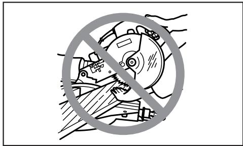
- NEVER hold workpiece on right side of blade with left hand or vice versa. This is called cross-armed cutting and exposes user to risk of SERIOUS PERSONAL INJURY as shown in the figure. ALWAYS use vise to secure workpiece.
- Do not abuse cord. Never yank cord to disconnect it from the receptacle. Keep cord away from heat, oil, water and sharp objects.
- NEVER stack workpieces on the table top to speed cutting operations. Cut only one piece at a time.
- Some material contains chemicals which may be toxic. Take caution to prevent dust inhalation and skin contact. Follow material supplier safety data.
SAVE THESE INSTRUCTIONS
WARNING:
MISUSE or failure to follow the safety rules stated in this instruction manual may cause serious personal injury. 5
INSTALLATION
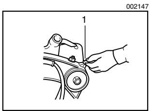
1. Handle latch
1. Bolt
FUNCTIONAL DESCRIPTION
1. Blade guard
Bench mounting
When the tool is shipped, the handle is locked in the lowered position by the handle latch. Release the handle latch by lowering the handle slightly and turn the handle latch to the released position.
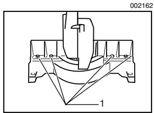
This tool should be bolted with four bolts to a level and stable surface using the bolt holes provided in the tool's base. This will help prevent tipping and possible injury.
CAUTION:
- Always be sure that the tool is switched off and unplugged before adjusting or checking function on the tool.
Blade guard
When lowering the handle, the blade guard rises automatically. The guard is spring loaded so it returns to its original position when the cut is completed and the handle is raised. NEVER DEFEAT OR REMOVE THE BLADE GUARD OR THE SPRING WHICH ATTACHES TO THE GUARD.
In the interest of your personal safety, always maintain the blade guard in good condition. Any irregular operation of the blade guard should be corrected immediately. Check to assure spring loaded return action of guard. NEVER USE THE TOOL IF THE BLADE GUARD OR SPRING ARE DAMAGED, FAULTY OR REMOVED. DOING SO IS HIGHLY DANGEROUS AND CAN CAUSE SERIOUS PERSONAL INJURY.
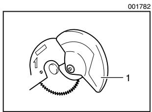
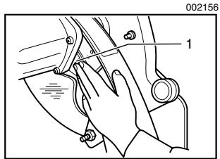
1. Blade guard
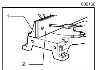
If the see-through blade guard becomes dirty, or sawdust adheres to it in such a way that the blade is no longer easily visible, unplug the saw and clean the guard carefully with a damp cloth. Do not use solvents or any petroleum-based cleaners on the plastic guard.
If the blade guard is especially dirty and vision through the guard is impaired, use the supplied socket wrench to loosen the hex bolt holding the center cover. Loosen the hex bolt by turning it counterclockwise and raise the blade guard and center cover. With the blade guard so positioned, cleaning can be more completely and efficiently accomplished. When cleaning is complete, reverse procedure above and secure bolt. Do not remove spring holding blade guard. If guard becomes discolored through age or UV light exposure, contact a Makita service center for a new guard. DO NOT DEFEAT OR REMOVE GUARD.
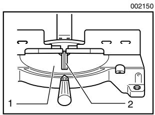
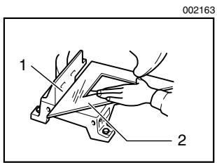
1. Turn base
2. Kerf board
Kerf board
This tool is provided with the kerf board in the turn base to minimize tearing on the exit side of a cut. If the kerf groove has not yet been cut in the kerf board by the factory, you should cut the groove before actually using the tool to cut a workpiece. Switch on the tool and lower the blade gently to cut a groove in the kerf board.
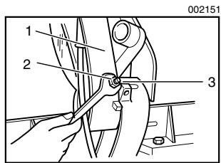
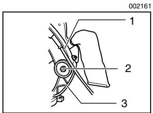
1. Gear housing
2. Hex nut
3. Adjusting bolt
Maintaining maximum cutting capacity
This tool is factory adjusted to provide the maximum cutting capacity for a 355 mm (14") saw blade.
When installing a new blade, always check the lower limit position of the blade and if necessary, adjust it as follows:
First, unplug the tool. Lower the handle completely. Loosen the hex nut at the rear of the gear housing. Use a screwdriver to turn the adjusting bolt until the periphery of the blade extends slightly below the top surface of the turn base at the point where the front face of the guide fence meets the top surface of the turn base.
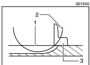
- Top surface of turn base
- Periphery of blade
- Guide fence
With the tool unplugged, rotate the blade by hand while holding the handle all the way down to be sure that the blade does not contact any part of the lower base. Re-adjust slightly, if necessary.
After adjusting, tighten the hex nut with the wrench while carefully holding the adjusting bolt in position with the screwdriver.
At this time, make sure that the handle can be locked in the lowered position by turning the handle latch. If the handle cannot be locked so, turn the adjusting bolt so that the handle can be locked in the lowered position.
CAUTION:
- After installing a new blade, always be sure that the blade does not contact any part of the lower base when the handle is lowered completely. Always do this with the tool unplugged.
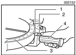
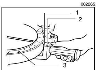
- Pointer
- Latch spring
- Miter scale
- Grip
Adjusting the miter angle
Loosen the grip by turning counterclockwise. Turn the turn base while pressing down the lock lever. When you have moved the grip to the position where the pointer points to the desired angle on the miter scale, securely tighten the grip clockwise.
CAUTION:
- When turning the turn base, be sure to raise the handle fully.
- After changing the miter angle, always secure the turn base by tightening the grip firmly.
Fence plate
The fence plate is designed to prevent smaller cutting scraps from jamming inside the blade case. The fence plate moves right or left automatically as the turn base is rotated.
- Lock-off button
- Switch trigger
Switch action
CAUTION:
- Before plugging in the tool, always check to see that the switch trigger actuates properly and returns to the "OFF" position when released.
- When not using the tool, remove the lock-off button and store it in a secure place. This prevents unauthorized operation.
- Do not pull the switch trigger hard without pressing in the lock-off button. This can cause switch breakage.
To prevent the switch trigger from being accidentally pulled, a lock-off button is provided. To start the tool, press in the lockoff button and pull the switch trigger. Release the switch trigger to stop.
WARNING:
- NEVER use tool without a fully operative switch trigger. Any tool with an inoperative switch is HIGHLY DANGEROUS and must be repaired before further usage.
- For your safety, this tool is equipped with a lock-off button which prevents the tool from unintended starting. NEVER use the tool if it runs when you simply pull the switch trigger without pressing the lock-off button. Return tool to a Makita service center for proper repairs BEFORE further usage.
- NEVER tape down or defeat purpose and function of lock-off button.
Electric brake
This tool is equipped with an electric blade brake. If the tool consistently fails to quickly stop blade after switch trigger release, have tool serviced at a Makita service center.
The blade brake system is not a substitute for blade guard. NEVER USE TOOL WITHOUT A FUNCTIONING BLADE GUARD. SERIOUS PERSONAL INJURY CAN RESULT.
ASSEMBLY
CAUTION:
- Always be sure that the tool is switched off and unplugged before carrying out any work on the tool.
Installing or removing saw blade
CAUTION:
- Always be sure that the tool is switched off and unplugged before installing or removing the blade.
- Use only the Makita socket wrench provided to install or remove the blade. Failure to do so may result in overtightening or insufficient tightening of the hex bolt. This could cause an injury.
To remove the blade, use the socket wrench to loosen the hex bolt holding the center cover by turning it counterclockwise. Raise the blade guard and center cover.
1. Socket wrench
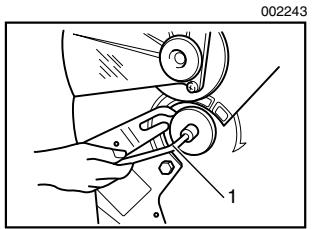
1. Shaft lock
1. Socket wrench
Press the shaft lock to lock the spindle and use the socket wrench to loosen the hex bolt clockwise. Then remove the hex bolt, outer flange and blade.
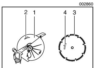
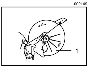
- Blade case
- Arrow
- Saw blade
- Arrow
To install the blade, mount it carefully onto the spindle, making sure that the direction of the arrow on the surface of the blade matches the direction of the arrow on the blade case. Install the outer flange and hex bolt, and then use the socket wrench to tighten the hex bolt (left-handed) securely counterclockwise while pressing the shaft lock.
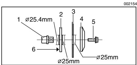
- Spindle
- Blade
-
Hex bolt
-
Inner flange
- Outer flange
6.25.4mm marking
CAUTION:
- The inner flange has a 25mm (63/64") diameter on one side and a 25.4mm (1") diameter on the other. The side with 25.4mm (1") diameter is marked by "25.4". Use the correct side for the hole diameter of the blade you intend to use. Mounting the blade on the wrong side can result in dangerous vibration.
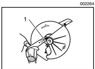
1. Pin
Slip the pin on the blade guard into the slot in the guide arm while returning the blade guard to its original fully closed position. Then tighten the hex bolt clockwise to secure the center cover. Lower the handle to make sure that the blade guard moves properly. Make sure shaft lock has released spindle before making cut.
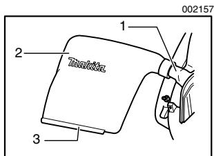
1. Dust nozzle
2. Dust bug
3. Fastener
Dust bag
The use of the dust bag makes cutting operations clean and dust collection easy. To attach the dust bag, fit it onto the dust nozzle.
When the dust bag is about half full, remove the dust bag from the tool and pull the fastener out. Empty the dust bag of its contents, tapping it lightly so as to remove particles adhering to the insides which might hamper further collection.
NOTE:
If you connect a Makita vacuum cleaner to your saw, more efficient and cleaner operations can be performed.
Securing workpiece
WARNING:
- It is extremely important to always secure the workpiece properly and tightly with the vise. Failure to do so can cause the tool to be damaged and/or the workpiece to be destroyed. PERSONAL INJURY MAY ALSO RESULT. Also, after a cutting operation, DO NOT raise the blade until the blade has come to a complete stop.
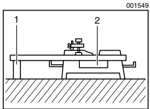
1. Support
2. Turn base
CAUTION:
- When cutting long workpieces, use supports that are as high as the top surface level of the turn base. Do not rely solely on the vertical vise and/or horizontal vise to secure the workpiece.
Thin material tends to sag. Support workpiece over its entire length to avoid blade pinch and possible KICKBACK.
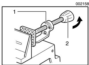
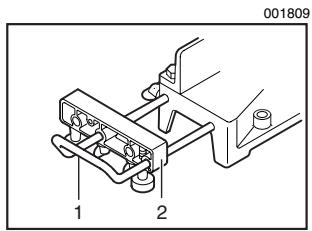
1. Projection
2. Vise knob
Horizontal vise
The horizontal vise can be installed on either the left or right side of the base. When performing 15^ or greater miter cuts, install the horizontal vise on the side opposite the direction in which the turn base is to be turned. By turning the vise knob counterclockwise, the screw is released and the vise shaft can be moved rapidly in and out. By turning the vise knob clockwise, the screw remains secured. To grip the workpiece, turn the vise knob gently clockwise until the projection reaches its topmost position, then fasten securely. If the vise knob is forced in or pulled out while being turned clockwise,
the projection may stop at an angle. In this case, turn the vise knob back counterclockwise until the screw is released, before turning again gently clockwise.
CAUTION:
- Grip the workpiece only when the projection is at the topmost position. Failure to do so may result in insufficient securing of the workpiece. This could cause the workpiece to be thrown, cause damage to the blade or cause the loss of control, which can result in PERSONAL INJURY.
- Holder
- Holder assembly
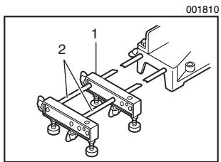
- Holder assembly
- Rod 12
OPERATION
Holders and holder assembly (optional accessories)
The holders and the holder assembly can be installed on either side as a convenient means of supporting workpieces horizontally. Install them as shown in the figure. Then tighten the screws firmly to secure the holders and the holder assembly.
When cutting long workpieces, use the holder-rod assembly (optional accessory). It consists of two holder assemblies and two rods 12.
CAUTION:
- Always support long workpieces level with the top surface of the turn base for accurate cuts and to prevent dangerous loss of control of the tool.
CAUTION:
- Before use, be sure to release the handle from the lowered position by turning the handle latch to the released position.
- Make sure the blade is not contacting the workpiece, etc. before the switch is turned on.
- Do not apply excessive pressure on the handle when cutting. Too much force may result in overload of the motor and/or decreased cutting efficiency. Push down handle with only as much force as is necessary for smooth cutting and without significant decrease in blade speed.
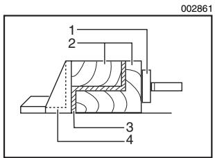
- Horizontal vise
- Spacer block
- Aluminum extrusion
- Guide fence
- Guide fence
-
Wood facing
-
Gently press down the handle to perform the cut. If the handle is pressed down with force or if lateral force is applied, the blade will vibrate and leave a mark (saw mark) in the workpiece and the precision of the cut will be impaired.
1. Press cutting
Secure the workpiece with the vise. Switch on the tool without the blade making any contact and wait until the blade attains full speed before lowering. Then gently lower the handle to the fully lowered position to cut the workpiece. When the cut is completed, switch off the tool and WAIT UNTIL THE BLADE HAS COME TO A COMPLETE STOP before returning the blade to its fully elevated position.
2. Miter cutting
Refer to the previously covered "Adjusting the miter angle".
3. Cutting aluminum extrusion
When securing aluminum extrusions, use spacer blocks or pieces of scrap as shown in the figure to prevent deformation of the aluminum. Use a cutting lubricant when cutting the aluminum extrusion to prevent build-up of the aluminum material on the blade.
CAUTION:
- Never attempt to cut thick or round aluminum extrusions. Thick aluminum extrusions may come loose during operation and round aluminum extrusions cannot be secured firmly with this tool.
4. Wood facing
Use of wood facing helps to assure splinter-free cuts in workpieces. Attach a wood facing to the guide fence using the holes in the guide fence.
See the figure concerning the dimensions for a suggested wood facing.
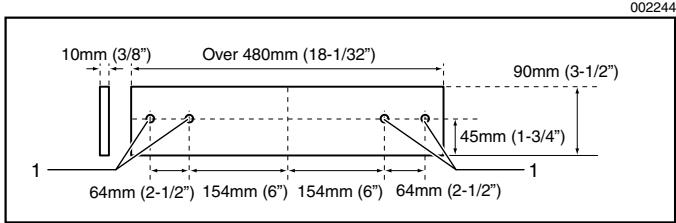
1. Hole
CAUTION:
- Use straight wood of even thickness as the wood facing.
- Use screws to attach the wood facing to the guide fence. The screws should be installed so that the screw heads are below the surface of the wood facing.
- When the wood facing is attached, do not turn the turn base with the handle lowered. The blade and/or the wood facing will be damaged.
NOTE:
- When the wood facing is attached, the maximum cutting capacities in width will be reduced by thickness of the wood facing.
5. Cutting repetitive lengths
When cutting several pieces of stock to the same length, ranging from 300mm (11-3/4") to 400mm (15-3/4"), use of the set plate (optional accessory) will facilitate more efficient operation. Install the set plate on the holder (optional accessory) as shown in the figure.
Align the cutting line on your workpiece with either the left or right side of the groove in the kerf board, and while holding the workpiece from moving, move the set plate flush against the end of the workpiece. Then secure the set plate with the screw. When the set plate is not used, loosen the screw and turn the set plate out of the way.
NOTE:
- Use of the holder-rod assembly (optional accessory) allows cutting repetitive lengths up to 2,200 ~mm (7.2 ft.) approximately.

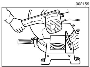
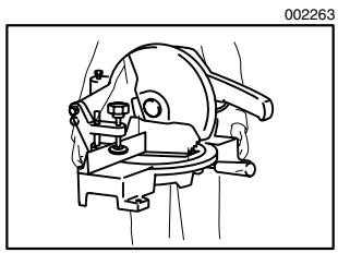
1. Handle latch
Carrying tool
Make sure that the tool is unplugged. Secure the turn base at right miter angle fully by means of the grip. Lower the handle fully and lock it in the lowered position by turning the handle latch to the locked position.
MAINTENANCE
Carry the tool by holding both sides of the tool base as shown in the figure. If you remove the holders, dust bag, etc., you can carry the tool more easily.
CAUTION:
- Always secure all moving portions before carrying the tool.
- Handle latch is for carrying and storage purposes only and not for any cutting operations.
CAUTION:
- Always be sure that the tool is switched off and unplugged before attempting to perform inspection or maintenance.
WARNING:
- Always be sure that the blade is sharp and clean for the best and safest performance.
Adjusting the cutting angle
This tool is carefully adjusted and aligned at the factory, but rough handling may have affected the alignment. If your tool is not aligned properly, perform the following:
Loosen the grip which secures the turn base. Turn the turn base so that the pointer points to 0^ on the miter scale. Then turn the turn base slightly clockwise and counterclockwise to seat the turn base in the 0^ miter notch. (Leave as it is if the pointer does not point to 0^ .) Loosen the hex bolts securing the guide fence using the socket wrench.
Lower the handle fully and lock it in the lowered position by turning the handle latch to the locked position. Square the side of the blade with the face of the guide fence using a triangular rule, try-square, etc. Then securely tighten the hex bolts on the guide fence in the order from the right side.
1. Hex bolt
1. Guide fence
2. Triangular rule
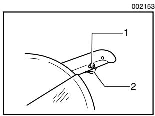
- Pointer
- Screws
- Miter scale
Make sure that the pointer on the indication plate points to 0^ on the miter scale. If the pointer does not point to 0^ , loosen the screws which secure the indication plate and adjust it so that the pointer will point to 0^ .
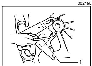
- Gear housing
- Hex lock nut
- Arm
Adjusting for smooth handle action
The hex lock nut which holds the gear housing and the arm has been factory adjusted to assure smooth handle action up and down and to guarantee precise cutting. Do not tamper with it. Should looseness develop at the gear housing and arm connection, perform the following adjustment. Work the handle up and down while tightening the hex lock nut; the best position to tighten the hex lock nut is just before the motor body weight is obvious.
After adjusting the hex lock nut, be sure that the handle returns automatically to the initial, raised position from any position. If the hex lock nut is too loose, the cutting accuracy will be affected; if it is too tight, it will be hard to work the handle up and down. Note that this is a self locking nut. It is a special type that does not loosen in normal use. It should not be overtightened or replaced with other types of nuts.
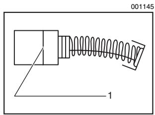
1. Limit mark
Replacing carbon brushes
Remove and check the carbon brushes regularly. Replace when they wear down to the limit mark. Keep the carbon brushes clean and free to slip in the holders. Both carbon brushes should be replaced at the same time. Use only identical carbon brushes.
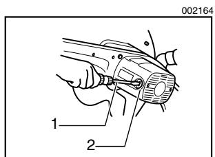
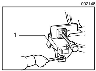
1. Screwdriver
2. Brush holder cap
Use a screwdriver to remove the brush holder caps. Take out the worn carbon brushes, insert the new ones and secure the brush holder caps.
After replacing brushes, plug in the tool and break in brushes by running tool with no load for about 10 minutes. Then check the tool while running and electric brake operation when releasing the switch trigger. If electric brake is not working well, ask your local Makita service center for repair.
After use
- After use, wipe off chips and dust adhering to the tool with a cloth or the like. Keep the blade guard clean according to the directions in the previously covered section titled "Blade guard". Lubricate the sliding portions with machine oil to prevent rust.
To maintain product SAFETY and RELIABILITY, repairs, any other maintenance or adjustment should be performed by Makita Authorized or Factory Service Centers, always using Makita replacement parts.
ACCESSORIES

CAUTION:
- These accessories or attachments are recommended for use with your Makita tool specified in this manual. The use of any other accessories or attachments might present a risk of injury to persons. Only use accessory or attachment for its stated purpose.
If you need any assistance for more details regarding these accessories, ask your local Makita service center.
- Steel & Carbide-tipped saw blades
| Crosscutting | For smoother cross grain cuts. Slices cleanly against the grain. |
| Fine cross cuts | For sand-free cuts cleanly against the grain. |
| Non-ferrous metals miter saw blades | For miters in aluminum, copper, brass, tubing, and other non-ferrous metals. |
- Vise assembly (Horizontal vise)
- Socket wrench 13
Holder set
Holder set (with set plate)
Holder rod assembly - Set plate
Dust bag
Triangular rule - Lock-off button (2 pcs.)
Memo

Stamp Timbre
Makita Canada Inc.
1950 Forbes Street,
Whitby, Ontario
L1N 7B7
Your answers to the following questions are appreciated.
1. This product was purchased from?
Hardware/lumber Store
Industrial Supply
Tool Distributor
□ Other ( )
3. How did you first learn of Makita Power Tools?
Magazine/Newspaper
Catalog
From dealer
□ Other ( )
Store display
2. Use of the product is intended for?
Construction trade
Home maintenance
Industrial maintenance
□ Other ( )
4. Most favored points are?
Design
Makita Brand
Features
Power
Size
□ Other ( )
Price
5. Any comments?
Certificate of Warranty Mail to Makita
Date Purchased
Month

Day

Year 20

Model No.
Serial No.
Initial Last Name

Postal Code
AGE:

Under 19

20-29

30-39

40-49

Over 50
Occupation:
Dealer's Name & Address:
Paste
Paste
Paste
Paste
Paste
Paste
Factory Service Centres
| Head Office: | 1950 Forbes St., Whitby, Ontario, L1N 7B7 (905) 571 - 2200 | 1-800-263-3734 | |
| Regional Office: | 11771 Hammersmith Way, Richmond B.C. V7A 5H6 | (604) 272 - 3104 | 1-800-663-0909 |
| Regional Office: (Montreal) | 6389 boul. Couture, St. Leonard, Quebec H1P 3J5 | (514) 323 - 1223 | 1-800-361-7049 |
| Dartmouth: | 202 Brownlow Avenue Dartmouth, N.S., B3B 1T5 | (902) 468 - 7064 | 1-888-625-4821 |
| Ville St. Laurent: (Montreal) | 1140 Rue Bégin, Ville St. Laurent, Quebec H4R 1X1 | (514) 745 - 5025 | 1-888-745-5025 |
| Les Saules: (Quebec) | 1200 St. Jean Baptiste, Unit 106, Les Saules, Quebec, G2E 5E8 | (418) 871 - 5720 | 1-800-663-5757 |
| Nepean: (Ottawa) | 210 Colonnade Road, Unit 11, Nepean, Ontario, K2E 7M1 | (613) 224 - 5022 | 1-888-560-2214 |
| Whitby: | 1950 Forbes St., Whitby, Ontario, L1N 7B7 (905) 571 - 2200 | 1-800-263-3734 | |
| London: | 317 Adelaide St. S., Unit 117, London, Ontario, N5Z 3L3 | (519) 686 - 3115 | 1-800-571-0899 |
| Mississauga: | 6350 Tomken Rd., Unit 8, Mississauga, Ontario, L5T 1Y3 | (905) 670 - 7255 | 1-888-221-9811 |
| Calgary: | #8-6115 Fourth St. S.E., Calgary Alberta, T2H 2H9 | (403) 243 - 3995 | 1-800-267-0445 |
| Edmonton: | 11614-149 Street, Edmonton, Alberta, T5M 3R3 | (780) 455 - 6644 | 1-888-455-6644 |
| Richmond: | 11771 Hammersmith Way, Richmond, B.C., V7A 5H6 | (604) 272 - 3104 | 1-800-663-0909 |
| Winnipeg: | 1670 St. James Street, Winnipeg, Manitoba, R3H 0L3 | (204) 694 - 0402 | 1-800-550-5073 |
| Saskatoon: | 206A-2750 Faithful Avenue Saskatoon, Saskatchewan, S7K 6M6 | (306) 931 - 0111 | 1-888-931-0111 |
For the authorized service centre nearest you please refer to the local yellow pages directory under "tools" or contact our customer service department (Tel) 1-800-263-3734
When you need service...
- Explain the problem in a letter
- Enclose the letter with the tool
- Package carefully and send prepaid to the nearest Makita factory or authorized service centre
CUSTOMER RECORD
DATE
PURCHASED:
DEALER'S NAME
& ADDRESS:
MODEL NO.:
SERIAL NO.:
MAKITA LIMITED ONE YEAR WARRANTY
Warranty Policy
Every Makita tool is thoroughly inspected and tested before leaving the factory. It is warranted to be free of defects from workmanship and materials for the period of ONE YEAR from the date of original purchase. Should any trouble develop during this one year period, return the COMPLETE tool, freight prepaid, to one of Makita's Factory or Authorized Service Centres. If inspection shows the trouble is caused by defective workmanship or material, Makita will repair (or at our option, replace) without charge.
This Warranty does not apply:
where normal maintenance is required,
- repairs have been made or attempted by others,
- the tool has been abused, misused or improperly maintained,
alterations have been made to the tool.
IN NO EVENT SHALL MAKITA BE LIABLE FOR ANY INDIRECT, INCIDENTAL OR CONSEQUENTIAL DAMAGES FROM THE SALE OR USE OF THE PRODUCT. THIS DISCLAIMER APPLIES BOTH DURING AND AFTER THE TERM OF THIS WARRANTY.
"The Makita Warranty is the only and the entire written warranty given by Makita for the Makita tools. No dealer or his agent or employee is authorized to extend or enlarge upon this warranty by any verbal or written statement or advertisement."
MAKITA DISCLAIMS LIABILITY FOR ANY IMPLIED WARRANTY INCLUDING IMPLIED WARRANTYES OF "MERCHANTABILITY" AND FITNESS FOR A SPECIFIC PURPOSE, AFTER THE ONE YEAR TERM OF THIS WARRANTY.
"This Warranty gives you specific rights. The provisions contained in this warranty are not intended to limit, modify, take away from, disclaim or exclude any warranties set forth in any provincial legislation. To the extent required by law, the provisions in any provincial or federal legislation with respect to warranties take precedence over the provisions in this warranty."
Makita Corporation
3-11-8, Sumiyoshi-cho,
Anjo, Aichi 446-8502 Japan