
YTH 20K46 - Tracteur de jardin HUSQVARNA - Notice d'utilisation et mode d'emploi gratuit
Retrouvez gratuitement la notice de l'appareil YTH 20K46 HUSQVARNA au format PDF.

| Type de produit | Tracteur de jardin autoporté |
| Marque | HUSQVARNA |
| Modèle | YTH 20K46 |
| Moteur | Kohler SV600, 20 ch (essence) |
| Capacité du réservoir de carburant | 9,5 L (2,5 gallons) sans plomb ordinaire |
| Type d'huile moteur | SAE 10W30 (au-dessus de 0°C) / SAE 5W30 (en dessous) |
| Capacité d'huile moteur | Avec filtre : 1,5 L ; sans filtre : 1,05 L |
| Bougie d'allumage | Champion RC12YC, écartement 0,76 mm (0,030") |
| Largeur de coupe | 117 cm (46 pouces) |
| Vitesse de déplacement avant | 0 – 8,4 km/h (0 – 5,2 mph) |
| Vitesse de déplacement arrière | 0 – 4,7 km/h (0 – 2,9 mph) |
| Système de charge | 15 A à 3600 tr/min |
| Batterie | 28 Ah, 230 A de démarrage à froid, taille U1R |
| Couple de serrage des lames | 61 – 75 N·m (45 – 55 lb·pi) |
| Transmission | Hydrostatique (marche avant/arrière par pédales) |
| Réglage de la hauteur de coupe | Environ 2,5 à 10 cm (1 à 4 pouces) |
| Système de sécurité | Présence opérateur, système de marche arrière (ROS), frein de stationnement |
| Entretien | Vidange d'huile tous les 50 h, filtre à air, bougie, courroies |
| Pression des pneus recommandée | Indiquée sur le flanc du pneu (généralement 14-20 PSI) |
| Poids | Environ 245 kg (540 lb) - estimation |
FOIRE AUX QUESTIONS - YTH 20K46 HUSQVARNA
Questions des utilisateurs sur YTH 20K46 HUSQVARNA
0 question sur cet appareil. Repondez a celles que vous connaissez ou posez la votre.
Poser une nouvelle question sur cet appareil
Téléchargez la notice de votre Tracteur de jardin au format PDF gratuitement ! Retrouvez votre notice YTH 20K46 - HUSQVARNA et reprennez votre appareil électronique en main. Sur cette page sont publiés tous les documents nécessaires à l'utilisation de votre appareil YTH 20K46 de la marque HUSQVARNA.
MODE D'EMPLOI YTH 20K46 HUSQVARNA
Husqvarna®

natural_image
Illustration of a modern electric scooter with visible wheels and front suspension (no text or symbols)917.240462
(YTH20K46)
Owner's Manual
Gasoline containing up to 10% ethanol (E10) is acceptable for use in this machine. The use of any gasoline exceeding 10% ethanol (E10) will void the product warranty.
DANGER: THIS CUTTING MACHINE IS CAPABLE OF AMPUTATING HANDS AND FEET AND THROWING OBJECTS. FAILURE TO OBSERVE THE FOLLOWING SAFETY INSTRUCTIONS COULD RESULT IN SERIOUS INJURY OR DEATH.

WARNING: In order to prevent accidental starting when setting up, transporting, adjusting or making repairs, always disconnect spark plug wire and place wire where it cannot contact spark plug.

WARNING: Do not coast down a hill in neutral, you may lose control of the tractor.

WARNING: Tow only the attachments that are recommended by and comply with specifications of the manufacturer of your tractor. Use common sense when towing. Operate only at the lowest possible speed when on a slope. Too heavy of a load, while on a slope, is dangerous. Tires can lose traction with the ground and cause you to lose control of your tractor.

WARNING

Engine exhaust, some of its constituents, and certain vehicle components contain or emit chemicals known to the State of California to cause cancer and birth defects or other reproductive harm.

WARNING

Battery posts, terminals and related accessories contain lead and lead compounds, chemicals known to the State of California to cause cancer and birth defects or other reproductive harm. Wash hands after handling.
I. GENERAL OPERATION
- Read, understand, and follow all instructions on the machine and in the manual before starting.
- Do not put hands or feet near rotating parts or under the machine. Keep clear of the discharge opening at all times.
- Only allow responsible adults, who are familiar with the instructions, to operate the machine.
- Clear the area of objects such as rocks, toys, wire, etc., which could be picked up and thrown by the blades.
- Be sure the area is clear of bystanders before operating. Stop machine if anyone enters the area.
• Never carry passengers. - Do not mow in reverse unless absolutely necessary. Always look down and behind before and while backing.
- Never direct discharged material toward anyone. Avoid discharging material against a wall or obstruction. Material may ricochet back toward the operator. Stop the blades when crossing gravel surfaces.
-
Do not operate machine without the entire grass catcher, discharge chute, or other safety devices in place and working.
-
Slow down before turning.
- Never leave a running machine unattended. Always turn off blades, set parking brake, stop engine, and remove keys before dismounting.
- Disengage blades when not mowing. Shut off engine and wait for all parts to come to a complete stop before cleaning the machine, removing the grass catcher, or unclogging the discharge chute.
- Operate machine only in daylight or good artificial light.
- Do not operate the machine while under the influence of alcohol or drugs.
- Watch for traffic when operating near or crossing roadways.
- Use extra care when loading or unloading the machine into a trailer or truck.
• Always wear eye protection when operating machine. - Data indicates that operators, age 60 years and above, are involved in a large percentage of riding mower-related injuries. These operators should evaluate their ability to operate the riding mower safely enough to protect themselves and others from serious injury.
- Follow the manufacturer's recommendation for wheel weights or counterweights.
- Keep machine free of grass, leaves or other debris build-up which can touch hot exhaust / engine parts and burn. Do not allow the mower deck to plow leaves or other debris which can cause build-up to occur. Clean any oil or fuel spillage before operating or storing the machine. Allow machine to cool before storage.
II. SLOPE OPERATION
Slopes are a major factor related to loss of control and tip-over accidents, which can result in severe injury or death. Operation on all slopes requires extra caution. If you cannot back up the slope or if you feel uneasy on it, do not mow it.
• Mow up and down slopes, not across.
- Watch for holes, ruts, bumps, rocks, or other hidden objects. Uneven terrain could overturn the machine. Tall grass can hide obstacles.
- Choose a low ground speed so that you will not have to stop or shift while on the slope.
- Do not mow on wet grass. Tires may lose traction. Always keep the machine in gear when going down slopes. Do not shift to neutral and coast downhill.
- Avoid starting, stopping, or turning on a slope. If the tires lose traction, disengage the blades and proceed slowly straight down the slope.
- Keep all movement on the slopes slow and gradual. Do not make sudden changes in speed or direction, which could cause the machine to roll over.
- Use extra care while operating machine with grass catchers or other attachments; they can affect the stability of the machine. Do no use on steep slopes.
- Do not try to stabilize the machine by putting your foot on the ground.
- Do not mow near drop-offs, ditches, or embankments. The machine could suddenly roll over if a wheel is over the edge or if the edge caves in.
III. CHILDREN
Tragic accidents can occur if the operator is not alert to the presence of children. Children are often attracted to the machine and the mowing activity. Never assume that children will remain where you last saw them.
- Keep children out of the mowing area and in the watchful care of a responsible adult other than the operator.
- Be alert and turn machine off if a child enters the area.
- Before and while backing, look behind and down for small children.
- Never carry children, even with the blades shut off. They may fall off and be seriously injured or interfere with safe machine operation. Children who have been given rides in the past may suddenly appear in the mowing area for another ride and be run over or backed over by the machine.
• Never allow children to operate the machine. - Use extra care when approaching blind corners, shrubs, trees, or other objects that may block your view of a child.
IV. TOWING
- Tow only with a machine that has a hitch designed for towing. Do not attach towed equipment except at the hitch point.
- Follow the manufacturer's recommendation for weight limits for towed equipment and towing on slopes.
- Never allow children or others in or on towed equipment.
- On slopes, the weight of the towed equipment may cause loss of traction and loss of control.
• Travel slowly and allow extra distance to stop.
V. SERVICE
SAFE HANDLING OF GASOLINE
To avoid personal injury or property damage, use extreme care in handling gasoline. Gasoline is extremely flammable and the vapors are explosive.
- Extinguish all cigarettes, cigars, pipes, and other sources of ignition.
• Use only approved gasoline container. - Never remove gas cap or add fuel with the engine running. Allow engine to cool before refueling.
• Never fuel the machine indoors. - Never store the machine or fuel container where there is an open flame, spark, or pilot light such as on a water heater or other appliances.
- Never fill containers inside a vehicle or on a truck or trailer bed with plastic liner. Always place containers on the ground away from your vehicle when filling.
- Remove gas-powered equipment from the truck or trailer and refuel it on the ground. If this is not possible, then refuel such equipment with a portable container, rather than from a gasoline dispenser nozzle.
- Keep the nozzle in contact with the rim of the fuel tank or container opening at all times until fueling is complete. Do not use a nozzle lock-open device.
- If fuel is spilled on clothing, change clothing immediately.
- Never overfill fuel tank. Replace gas cap and tighten securely.
GENERAL SERVICE
• Never operate machine in a closed area.
- Keep all nuts and bolts tight to be sure the equipment is in safe working condition.
- Never tamper with safety devices. Check their proper operation regularly.
- Keep machine free of grass, leaves, or other debris build-up. Clean oil or fuel spillage and remove any fuel-soaked debris. Allow machine to cool before storing.
- If you strike a foreign object, stop and inspect the machine. Repair, if necessary, before restarting.
- Never make any adjustments or repairs with the engine running.
- Check grass catcher components and the discharge chute frequently and replace with manufacturer's recommended parts, when necessary.
- Mower blades are sharp. Wrap the blade or wear gloves, and use extra caution when servicing them.
- Check brake operation frequently. Adjust and service as required.
- Maintain or replace safety and instruction labels, as necessary.


- Be sure the area is clear of bystanders before operating. Stop machine if anyone enters the area.
• Never carry passengers. - Do not mow in reverse unless absolutely necessary. Always look down and behind before and while backing.
- Never carry children, even with the blades shut off. They may fall off and be seriously injured or interfere with safe machine operation. Children who have been given rides in the past may suddenly appear in the mowing area for another ride and be run over or backed over by the machine.
- Keep children out of the mowing area and in the watchful care of a responsible adult other than the operator.
- Be alert and turn machine off if a child enters the area.
- Before and while backing, look behind and down for small children.
• Mow up and down slopes (15° Max), not across. - Choose a low ground speed so that you will not have to stop or shift while on the slope.
- Avoid starting, stopping, or turning on a slope. If the tires lose traction, disengage the blades and proceed slowly straight down the slope.
- If machine stops while going uphill, disengage blades, shift into reverse and back down slowly.
- Do not turn on slopes unless necessary, and then, turn slowly and gradually downhill, if possible.
PRODUCT SPECIFICATIONS
| Gasoline Capacity and type: | 2.5 Gallons (9,5 L) Unleaded Regular |
| Oil Type (API-SG-SL): | SAE 10W30 (above 32°F/0°C) SAE 5W30 (below 32°F/0°C) |
| Oil Capacity: | W/ Filter: 51 oz (1.5 L) W/O Filter: 35 oz (1.05 L) |
| Spark Plug: | Champion RC12YC (Gap: .030") |
| Ground Speed (MPH): | Forward: 0 – 5.2 Reverse: 0 – 2.9 |
| Charging System | 15 Amps @ 3600 RPM |
| Battery: | AMP/HR: 28 MIN. CCA: 230 Case Size: U1R |
| Blade Bolt Torque: | 45-55 Ft. Lbs. |
CONGRATULATIONS on your purchase of a new tractor. It has been designed, engineered and manufactured to give you the best possible dependability and performance.
Should you experience any problem you cannot easily remedy, please contact your nearest authorized servicecenter/department We have competent, well-trained technicians and the proper tools to service or repair this tractor.
Please read and retain this manual. The instructions will enable you to assemble and maintain your tractor properly. Always observe the "SAFETY RULES".
CUSTOMER RESPONSIBILITIES
- Read and observe the safety rules.
- Follow a regular schedule in maintaining, caring for and using your tractor.
- Follow the instructions under "Maintenance" and "Storage" sections of this manual.
WARNING: This tractor is equipped with an internal combustion engine and should not be used on or near any un-improved forest-covered, brush-covered or grass-covered land unless the engine's exhaust system is equipped with a spark arrester meeting applicable local or state laws (if any). If a spark arrester is used, it should be maintained in effective working order by the operator.
In the state of California the above is required by law (Section 4442 of the California Public Resources Code). Other states may have similar laws. Federal laws apply on federal lands.
A spark arrester for the muffler is available through your nearest authorized service center/department.
TABLE OF CONTENTS
| SAFETY RULES | 2-3 |
| PRODUCT SPECIFICATIONS | 4 |
| CUSTOMER RESPONSIBILITIES | 4 |
| ASSEMBLY | 5-6 |
| OPERATION | 7-13 |
| MAINTENANCE SCHEDULE | 14 |
| MAINTENANCE | 14-17 |
| SERVICE AND ADJUSTMENTS | 18-23 |
| STORAGE | 24 |
| TROUBLESHOOTING | 25-26 |
| REPAIR PARTS | 27-42 |
| TRANSAXLE | 43 |
| ENGINE BREAKDOWN | 44-52 |
UNASSEMBLED PARTS

(2) Keys

Slope Sheet
natural_image
Abstract diagram with shaded regions and a central black rectangle, no text or symbols presentASSEMBLY
Your new tractor has been assembled at the factory with the exception of those parts left unassembled for shipping purposes.
TOOLS REQUIRED FOR ASSEMBLY
A socket wrench set will make assembly easier. Standard wrench sizes are listed.
(1) 1/2" wrench Tire pressure gauge
(2) 7/16" wrenches Utility knife
Pliers
When right or left hand is mentioned in this manual, it means when you are in the operating position (seated behind the steering wheel).
TO REMOVE TRACTOR FROM CARTON
UNPACK CARTON
- Remove all accessible loose parts and parts cartons from carton.
- Cut along dotted lines on all four panels of carton. Remove end panels and lay side panels flat.
- Check for any additional loose parts or cartons and remove.
BEFORE REMOVING TRACTOR FROM SKID
TO CHECK BATTERY (See Fig. 1)
- Lift seat to raised position.
NOTE: If this battery is put into service after month and year indicated on label (label is located between terminals) charge battery for minimum of one hour at 6-10 amps. (See "BATTERY" in Maintenance section of this manual for charging instructions).
- For battery and battery cable installation see "REPLACING BATTERY" in the "Service and Adjustments" section in this manual.
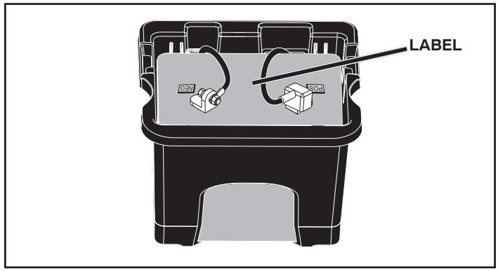
Fig. 1
ADJUST SEAT (See Fig. 2)
- Sit in seat.
- Lift up adjustment lever (A) and slide seat until a comfortable position is reached which allows you to press clutch/brake pedal all the way down.
- Release lever to lock seat in position.
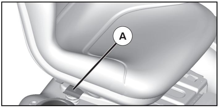
Fig. 2
ASSEMBLY
NOTE: You may now roll your tractor off the skid. Follow the instructions below to remove the tractor from the skid.
WARNING: Before starting, read, understand and follow all instructions in the Operation section of this manual. Be sure tractor is in a well-ventilated area. Be sure the area in front of tractor is clear of other people and objects.
TO ROLL TRACTOR OFF SKID (See Operation section for location and function of controls)
- Raise attachment lift lever to its highest position.
- Release parking brake by depressing brake pedal.
- Place freewheel control in disengaged position to disengage transmission (See “TO TRANSPORT” in the Operation section of this manual).
• Roll tractor forward off skid.
Continue with the instructions that follow.
CHECK TIRE PRESSURE
The tires on your tractor were overinflated at the factory for shipping purposes. Correct tire pressure is important for best cutting performance.
- Reduce tire pressure to PSI shown on tires.
CHECK DECK LEVELNESS
For best cutting results, mower housing should be properly leveled. See “TO LEVEL MOWER HOUSING” in the Service and Adjustments section of this manual.
CHECK FOR PROPER POSITION OF ALL BELTS
See the figures that are shown for replacing motion and mower blade drive belts in the Service and Adjustments section of this manual. Verify that the belts are routed correctly.
CHECK BRAKE SYSTEM
After you learn how to operate your tractor, check to see that the brake is operating properly. See “TO CHECK BRAKE” in the Service and Adjustments section of this manual.
√ CHECKLIST
BEFORE YOU OPERATE YOUR NEW TRACTOR, WE WISH TO ASSURE THAT YOU RECEIVE THE BEST PERFORMANCE AND SATISFACTION FROM THIS QUALITY PRODUCT.
PLEASE REVIEW THE FOLLOWING CHECKLIST:
√ All assembly instructions have been completed.
√ No remaining loose parts in carton.
√ Battery is properly prepared and charged.
√ Seat is adjusted comfortably and tightened securely.
√ All tires are properly inflated. (For shipping purposes, the tires were overinflated at the factory).
√ Be sure mower deck is properly leveled side-to-side/front-to-rear for best cutting results. (Tires must be properly inflated for leveling).
√ Check mower and drive belts. Be sure they are routed properly around pulleys and inside all belt keepers.
√ Check wiring. See that all connections are still secure and wires are properly clamped.
√ Before driving tractor, be sure freewheel control is in “transmission engaged” position (See “TO TRANSPORT” in the Operation section of this manual).
WHILE LEARNING HOW TO USE YOUR TRACTOR, PAY EXTRA ATTENTION TO THE FOLLOWING IMPORTANT ITEMS:
√ Engine oil is at proper level.
√ Fuel tank is filled with fresh, clean, regular unleaded gasoline.
√ Become familiar with all controls, their location and function. Operate them before you start the engine.
√ Be sure brake system is in safe operating condition.
√ Be sure Operator Presence System and Reverse Operation System (ROS) are working properly (See the Operation and Maintenance sections in this manual).
√ It is important to purge the transmission before operating your tractor for the first time. Follow proper starting and transmission purging instructions (See "TO START ENGINE" and "PURGE TRANSMISSION" in the Operation section of this manual).
OPERATION
These symbols may appear on your tractor or in literature supplied with the product. Learn and understand their meaning.
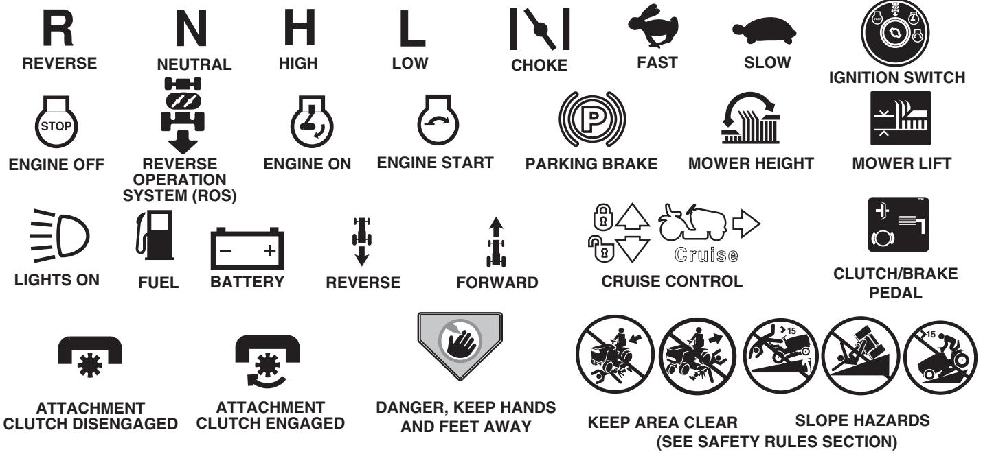


FREE WHEEL
(Automatic Models only)

Failure to follow instructions could result in serious injury or death. The safety alert symbol is used to identify safety information about hazards which can result in death, serious injury and/or property damage.

DANGER indicates a hazard which, if not avoided, will result in death or serious injury.

WARNING indicates a hazard which, if not avoided, could result in death or serious injury.

CAUTION indicates a hazard which, if not avoided, might result in minor or moderate injury.
CAUTION when used without the alert symbol, indicates a situation that could result in damage to the tractor and/or engine.

HOT SURFACES indicates a hazard which, if not avoided, could result in death, serious injury and/or property damage.

FIRE indicates a hazard which, if not avoided, could result in death, serious injury and/or property damage.
OPERATION
KNOW YOUR TRACTOR
READ THIS OWNER'S MANUAL AND SAFETY RULES BEFORE OPERATING YOUR TRACTOR
Compare the illustrations with your tractor to familiarize yourself with the locations of various controls and adjustments. Save this manual for future reference.
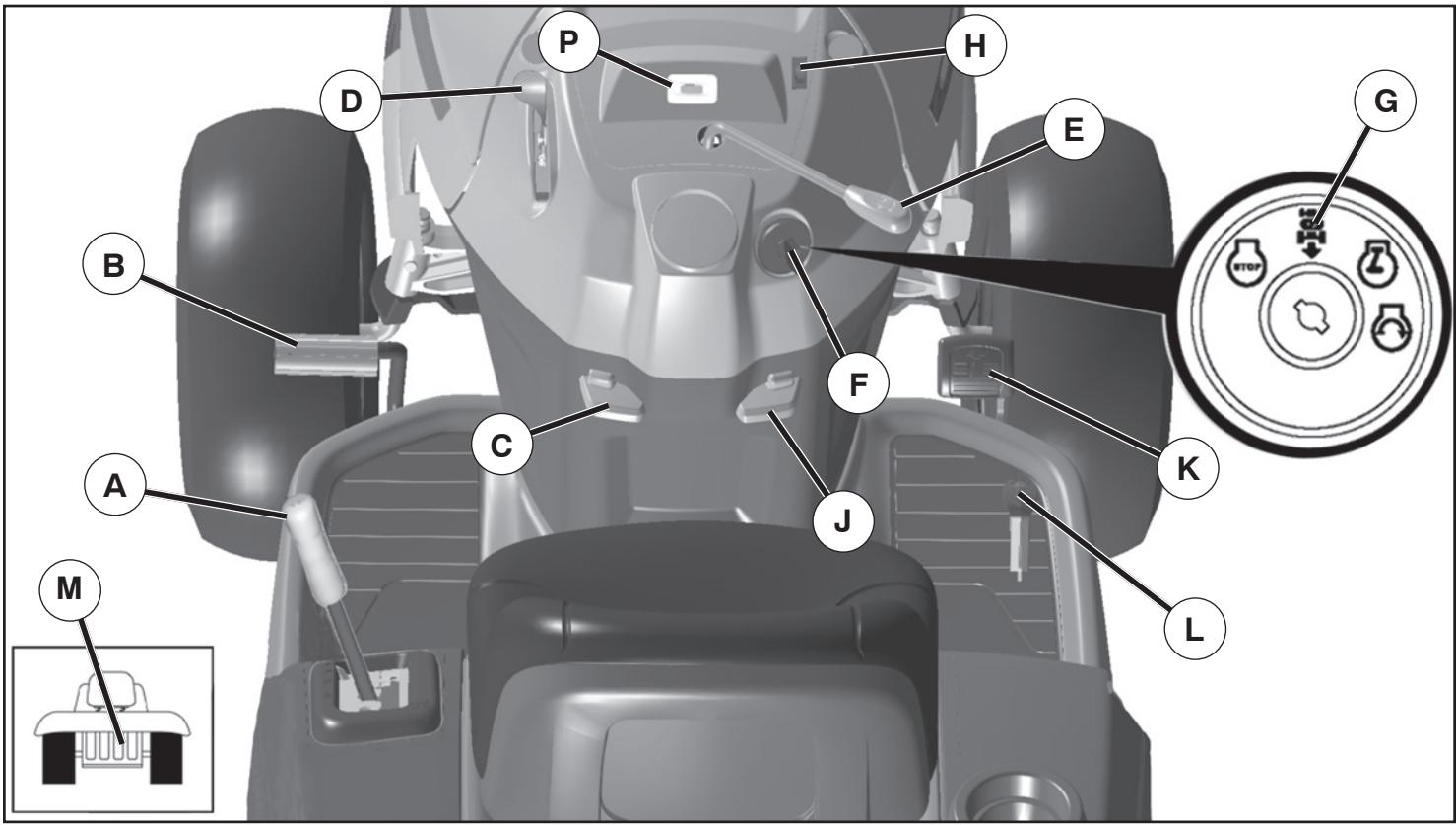
Fig. 3
Our tractors conform to the applicable safety standards of the American National Standards Institute.
(A) ATTACHMENT LIFT LEVER - Used to raise and lower the mower or other attachments mounted to your tractor.
(B) BRAKE PEDAL - Used for braking the tractor and starting the engine.
(C) PARKING BRAKE - Locks clutch/brake pedal into the brake position.
(D) THROTTLE/CHOKE CONTROL - Used for starting and controlling engine speed.
(E) ATTACHMENT CLUTCH LEVER - Used to engage the mower blades, or other attachments mounted to your tractor.
(F) IGNITION SWITCH - Used for starting and stopping the engine.
(G) REVERSE OPERATION SYSTEM (ROS) "ON" POSITION - Allows operation of mower or other powered attachment while in reverse.
(H) LIGHT SWITCH - Turns the headlights on and off.
(J) CRUISE CONTROL LEVER - Used to set forward movement of tractor at desired speed without holding the forward drive pedal.
(K) FORWARD DRIVE PEDAL - Used for forward movement of tractor.
(L) REVERSE DRIVE PEDAL - Used for reverse movement of tractor.
(M) FREEWHEEL CONTROL - Disengages transmission for pushing or slowly towing the tractor with the engine off.
(P) SERVICE REMINDER / HOUR METER - Indicates when service is required for the engine and mower.
OPERATION

The operation of any tractor can result in foreign objects thrown into the eyes, which can result in severe eye damage. Always wear safety glasses or eye shields while operating your tractor or performing any adjustments or repairs. We recommend standard safety glasses or a wide vision safety mask worn over spectacles.
HOW TO USE YOUR TRACTOR
TO SET PARKING BRAKE (See Fig. 4)
Your tractor is equipped with an operator presence sensing switch. When engine is running, any attempt by the operator to leave the seat without first setting the parking brake will shut off the engine.
• Depress brake pedal (B) all the way down and hold.
- Pull parking brake lever (C) up and hold, release pressure from brake pedal (B), then release parking brake lever. Pedal should remain in brake position. Make sure parking brake will hold tractor secure.
natural_image
Mechanical assembly diagram showing a vehicle's wheel and suspension components (no text or symbols)Fig. 4
STOPPING (See Fig. 5)
MOWER BLADES -
- To stop mower blades, move attachment clutch lever to "DISENGAGED" position.
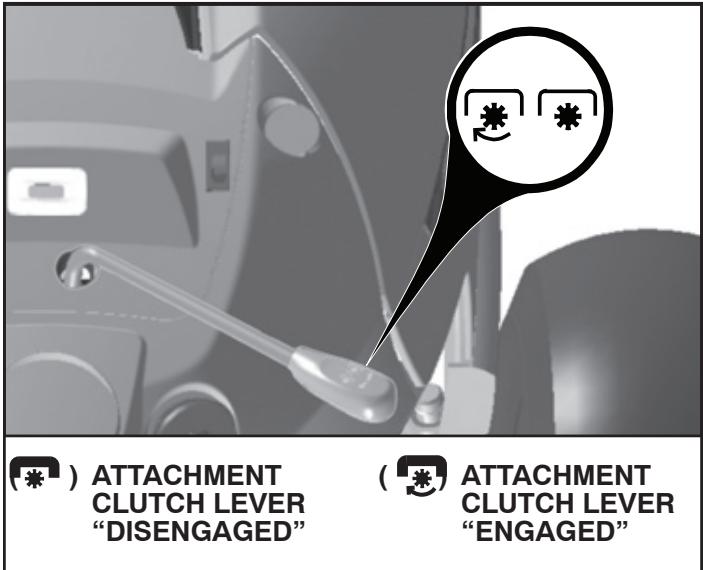
Fig. 5
GROUND DRIVE -
- To stop ground drive, depress brake pedal into full "BRAKE" position.
IMPORTANT: FORWARD AND REVERSE DRIVE PEDALS RETURN TO NEUTRAL POSITION WHEN NOT DEPRESSED. ENGINE -
- Move throttle control between half and full speed (fast) position.
NOTE: Failure to move throttle control between half and full speed (fast) position, before stopping may cause engine to "backfire".
- Turn ignition key (F) to "STOP" position and remove key. Always remove key when leaving tractor to prevent unauthorized use.
IMPORTANT: LEAVING THE IGNITION SWITCH IN ANY POSITION OTHER THAN "STOP" WILL CAUSE THE BATTERY TO BE DISCHARGED, (DEAD).
NOTE: Under certain conditions when tractor is standing idle with the engine running, hot engine exhaust gases may cause “browning” of grass. To eliminate this possibility, always stop engine when stopping tractor on grass areas.

CAUTION: Always stop tractor completely, as described above, before leaving the operator's position; to empty grass catcher, etc.
TO USE THROTTLE CONTROL (D) (See Fig. 6)
Always operate engine at full speed (fast).
- Operating engine at less than full speed (fast) reduces engines operating efficiency.
• Full speed (fast) offers the best bagging and mower performance.
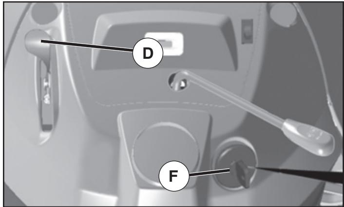
Fig. 6
OPERATION
TO MOVE FORWARD AND BACKWARD (See Fig. 7)
The direction and speed of movement is controlled by the forward and reverse drive pedals.
- Start tractor and release parking brake.
- Slowly depress forward (K) or reverse (L) drive pedal to begin movement. Ground speed increases the further down the pedal is depressed.
TO USE CRUISE CONTROL (J) (See Fig. 7)
The cruise control feature can be used for forward travel only.
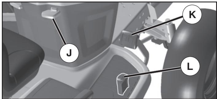
Fig. 7
SYSTEM CHARACTERISTICS
The cruise control should only be used while mowing or transporting on relatively smooth, straight surfaces. Other conditions such as trimming at slow speeds may cause the cruise control to disengage. Do not use the cruise control on slopes, rough terrian or while trimming or turning.
- With forward drive pedal depressed to desired speed, pull cruise control lever (J) up and hold while lifting your foot off the pedal, then release the lever.
To disengage the cruise control, depress the brake pedal or tap on forward drive pedal.
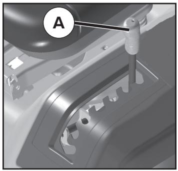
TO ADJUST MOWER CUTTING HEIGHT (See Fig. 8)
The position of the attachment lift lever (A) determines the cutting height.
natural_image
Mechanical component diagram showing a tool interacting with a gear-like structure (no text or symbols visible)Fig. 8
-
Put attachment lift lever in desired cutting height slot.
The cutting height range is approximately 1" to 4". The heights are measured from the ground to the blade tip with the engine not running. These heights are approximate and may vary depending upon soil conditions, height of grass and types of grass being mowed. -
The average lawn should be cut to approximately 2-1/2" during the cool season and to over 3" during hot months. For healthier and better looking lawns, mow often and after moderate growth.
- For best cutting performance, grass over 6" in height should be mowed twice. Make the first cut relatively high; the second to desired height.
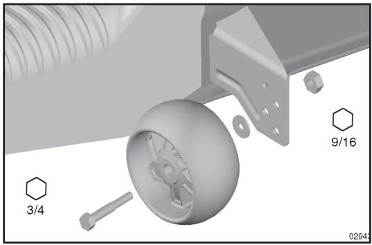
TO ADJUST GAUGE WHEELS (See Fig. 9)
Gauge wheels are properly adjusted when they are slightly off the ground when mower is at the desired cutting height in operating position. Gauge wheels then keep the deck in proper position to help prevent scalping in most terrain conditions.
NOTE: Adjust gauge wheels with tractor on a flat level surface.
- Adjust mower to desired cutting height (See "TO ADJUST MOWER CUTTING HEIGHT" in this section of manual).
- With mower in desired height of cut position, gauge wheels should be assembled so they are slightly off the ground. Install gauge wheel in appropriate hole. Tighten securely.
- Repeat for all, installing gauge wheel in same adjustment hole.
natural_image
3D mechanical assembly diagram showing a wheel, bracket, and nut components (no text or symbols)Fig. 9
TO OPERATE MOWER (See Fig. 10)
Your tractor is equipped with an operator presence sensing switch. Any attempt by the operator to leave the seat with the engine running and the attachment clutch engaged will shut off the engine. You must remain fully and centrally positioned in the seat to prevent the engine from hesitating or cutting off when operating your equipment on rough, rolling terrain or hills.
- Select desired height of cut with attachment lift lever.
- Start mower blades by engaging attachment clutch.
TO STOP MOWER BLADES -
Disengage attachment clutch control.
OPERATION
natural_image
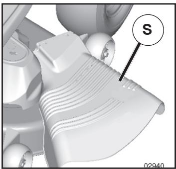
Close-up of a mechanical component with layered structure and a labeled section 'S' (no readable text or symbols beyond label)Fig. 10

CAUTION: Do not operate the mower without either the entire grass catcher, on mowers so equipped, or the deflector shield (S) in place.
REVERSE OPERATION SYSTEM (ROS) (See Fig. 11)
Your tractor is equipped with a Reverse Operation System (ROS). Any attempt by the operator to travel in the reverse direction with the attachment clutch engaged will shut off the engine unless ignition key is placed in the ROS "ON" position.
⚠ WARNING: Backing up with the attachment clutch engaged while mowing is strongly discouraged. Turning the ROS "ON", to allow reverse operation with the attachment clutch engaged, should only be done when the operator decides it is necessary to reposition the machine with the attachment engaged. Do not mow in reverse unless absolutely necessary.
USING THE REVERSE OPERATION SYSTEM -
Only use if you are certain no children or other bystanders will enter the mowing area.
• Depress brake pedal all the way down.
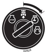
- With engine running, turn ignition key counterclockwise to ROS "ON" position.

ROS "ON" POSITION
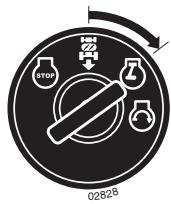
ENGINE "ON" POSITION (NORMAL OPERATING)
Fig. 11
- Look down and behind before and while backing.
- Slowly depress reverse drive pedal to start movement.
- When use of the ROS is no longer needed, turn the ignition key clockwise to engine "ON" position.
TO OPERATE ON HILLS

CAUTION: Do not drive up or down hills with slopes greater than 15^ and do not drive across any slope.
- Choose the slowest speed before starting up or down hills.
- Avoid stopping or changing speed on hills.
- If stopping is absolutely necessary, push brake pedal quickly to brake position and engage parking brake.
- To restart movement, slowly release parking brake and brake pedal.
- Slowly depress appropriate drive pedal to slowest setting.
• Make all turns slowly.
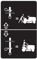
TO TRANSPORT (See Figs. 3 and 12)
When pushing or towing your tractor, be sure to disengage transmission by placing freewheel control in freewheeling position. Free wheel control is located at the rear drawbar of tractor.
- Raise attachment lift to highest position with attachment lift control.
- Pull freewheel control out and down into the slot and release so it is held in the disengaged position.
- Do not push or tow tractor at more than two (2) MPH.
• To reengage transmission, reverse above procedure.
NOTE: To protect hood from damage when transporting your tractor on a truck or a trailer, be sure hood is closed and secured to tractor. Use an appropriate means of tying hood to tractor (rope, cord, etc.).
TRANSMISSION ENGAGED


TRANSMISSION DISENGAGED
Fig. 12
TOWING CARTS AND OTHER ATTACHMENTS
Tow only the attachments that are recommended by and comply with specifications of the manufacturer of your tractor. Use common sense when towing. Too heavy of a load, while on a slope, is dangerous. Tires can lose traction with the ground and cause you to lose control of your tractor.
SERVICE REMINDER/HOUR METER
Service reminder shows the total number of hours the engine has run and flashes to indicate that the engine or mower needs servicing. When service is required, the service reminder will flash for two hours. To service engine and mower, see the Maintenance section of this manual.
NOTE: Service reminder runs when the ignition key is in any position but "STOP". For accurate reading, be sure key remains in the "STOP" position when engine is not running.
OPERATION
BEFORE STARTING THE ENGINE
CHECK ENGINE OIL LEVEL
The engine in your tractor has been shipped, from the factory, already filled with summer weight oil.
- Check engine oil with tractor on level ground.
- Remove oil fill cap/dipstick and wipe clean, reinsert the dipstick and screw cap tight, wait for a few seconds, remove and read oil level. If necessary, add oil until "FULL" mark on dipstick is reached. Do not overfill.
- For cold weather operation you should change oil for easier starting (See "OIL VISCOSITY CHART" in the Maintenance section of this manual).
- To change engine oil, see the Maintenance section in this manual.
ADD GASOLINE
- Fill fuel tank to bottom of filler neck. Do not overfill. Use fresh, clean, regular unleaded gasoline with a minimum of 87 octane. (Use of leaded gasoline will increase carbon and lead oxide deposits and reduce valve life). Do not mix oil with gasoline. Purchase fuel in quantities that can be used within 30 days to assure fuel freshness.

CAUTION: Wipe off any spilled oil or fuel. Do not store, spill or use gasoline near an open flame.
IMPORTANT: WHEN OPERATING IN TEMPERATURES BELOW 32°F(0°C), USE FRESH, CLEAN WINTER GRADE GASOLINE TO HELP INSURE GOOD COLD WEATHER STARTING.
CAUTION: Alcohol blended fuels (called gasohol or using ethanol or methanol) can attract moisture which leads to separation and formation of acids during storage. Acidic gas can damage the fuel system of an engine while in storage. To avoid engine problems, the fuel system should be emptied before storage of 30 days or longer. Drain the gas tank, start the engine and let it run until the fuel lines and carburetor are empty. Use fresh fuel next season. See Storage Instructions for additional information. Never use engine or carburetor cleaner products in the fuel tank or permanent damage may occur.
TO START ENGINE (See Fig. 3)
When starting the engine for the first time or if the engine has run out of fuel, it will take extra cranking time to move fuel from the tank to the engine.
- Be sure freewheel control is in the transmission engaged position.
- Sit on seat in operating position, depress brake pedal and set parking brake.
- Move attachment clutch to "DISENGAGED" position.
- Move throttle control to choke position.
NOTE: Before starting, read the warm and cold starting procedures below.
- Insert key into ignition and turn key clockwise to "START" position and release key as soon as engine starts. Do not run starter continuously for more than fifteen seconds per minute. If the engine does not start after several attempts, move throttle control to fast position, wait a few minutes and try again. If engine still does not start, move the throttle control back to the choke position and retry.
WARM WEATHER STARTING (50° F/10° C and above)
- When engine starts, move the throttle control to the fast position.
- The attachments and ground drive can now be used. If the engine does not accept the load, restart the engine and allow it to warm up for one minute using the choke as described above.
COLD WEATHER STARTING (50° F/10° C and below)
- When engine starts, allow engine to run with the throttle control in the choke position until the engine runs roughly, then move throttle control to fast position. This may require an engine warm-up period from several seconds to several minutes, depending on the temperature.
AUTOMATIC TRANSMISSION WARM UP
- Before driving the unit in cold weather, the transmission should be warmed up as follows:
- Be sure the tractor is on level ground.
- Release the parking brake and let the brake slowly return to operating position.
- Allow one minute for transmission to warm up. This can be done during the engine warm up period.
- The attachmentscanalsobeusedduringtheenginewarm-up period after the transmission has been warmed up.
NOTE: If at a high altitude (above 3000 feet) or in cold temperatures (below 32^ F/ 10^ C) the carburetor fuel mixture may need to be adjusted for best engine performance. See "TO ADJUST CARBURETOR" in the Service and Adjustments section of this manual.
OPERATION
PURGE TRANSMISSION

CAUTION: Never engage or disengage freewheel lever while the engine is running.
To ensure proper operation and performance, it is recommended that the transmission be purged before operating tractor for the first time. This procedure will remove any trapped air inside the transmission which may have developed during shipping of your tractor.
IMPORTANT: SHOULD YOUR TRANSMISSION REQUIRE REMOVAL FOR SERVICE OR REPLACEMENT, IT SHOULD BE PURGED AFTER REINSTALLATION BEFORE OPERATING THE TRACTOR.
- Place tractor safely on a level surface - that is clear and open - with engine off and parking brake set.
- Disengage transmission by placing freewheel control in freewheeling position (See “TO TRANSPORT” in this section of manual).
- Sitting in the tractor seat, start engine. After the engine is running, move throttle control to slow position. Disengage parking brake

CAUTION: At any time, there may be movement of the drive wheels.
- Depress forward drive pedal to full forward position, hold for five (5) seconds and release pedal. Depress reverse drive pedal to full reverse position, hold for five (5) seconds and release pedal. Repeat this procedure three (3) times.
- Shut off engine and set parking brake.
- Engage transmission by placing freewheel control in engaged position (See "TO TRANSPORT" in this section of manual).
- Sitting in the tractor seat, start engine. After the engine is running, move throttle control to half (1/2) speed. Disengage parking brake.
- Drive tractor forward for approximately five feet then backwards for five feet. Repeat this driving procedure three times.
Your transmission is now purged and now ready for normal operation.
MOWING TIPS
- Tire chains cannot be used when the mower housing is attached to tractor.
- Mower should be properly leveled for best mowing performance. See “TO LEVEL MOWER HOUSING” in the Service and Adjustments section of this manual.
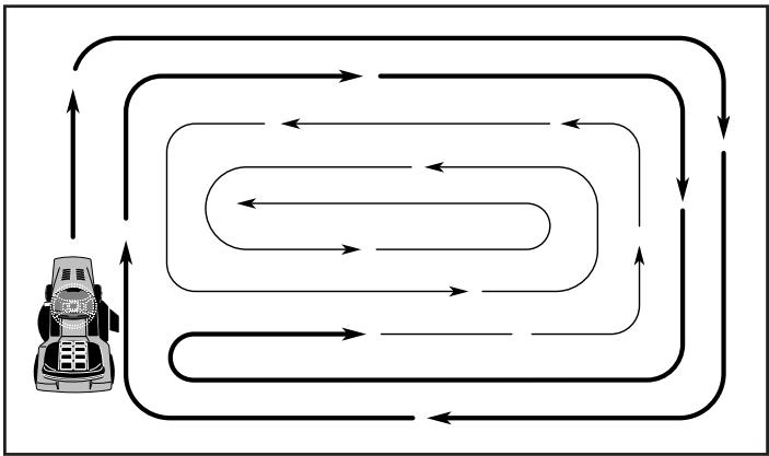
• The left hand side of mower should be used for trimming. - Drive so that clippings are discharged onto the area that has been cut. Have the cut area to the right of the tractor. This will result in a more even distribution of clippings and more uniform cutting.
- When mowing large areas, start by turning to the right so that clippings will discharge away from shrubs, fences, driveways, etc. After one or two rounds, mow in the opposite direction making left hand turns until finished (See Fig. 13).
flowchart
graph TD
    A["Start"] --> B{Condition}
    B -->|Yes| C["Drive"]
    B -->|No| D["Car"]
    C --> E["End"]
    D --> E
    E --> F["Continue"]
    F --> G["End"]
Fig. 13
- If grass is extremely tall, it should be mowed twice to reduce load and possible fire hazard from dried clippings. Make first cut relatively high; the second to the desired height.
- Do not mow grass when it is wet. Wet grass will plug mower and leave undesirable clumps. Allow grass to dry before mowing.
- Always operate engine at full throttle when mowing to assure better mowing performance and proper discharge of material. Regulate ground speed by selecting a low enough gear to give the mower cutting performance as well as the quality of cut desired.
- When operating attachments, select a ground speed that will suit the terrain and give best performance of the attachment being used.
MAINTENANCE
| MAINTENANCE SCHEDULE | BEFORE EACH USE | EVERY 8 HOURS | EVERY 25 HOURS | EVERY 50 HOURS | EVERY 100 HOURS | EVERY SEASON | BEFORE STORAGE | |
| TRACTOR | Check Brake Operation | √ | √ | |||||
| Check Tire Pressure | √ | √ | ||||||
| Check Operator Presence & ROS Systems | √ | |||||||
| Check for Loose Fasteners | √ | √ | √ | |||||
| Check/Replace Mower Blades | 3 | |||||||
| Lubrication Chart | √ | √ | ||||||
| Check Battery Level | 4 | |||||||
| Clean Battery and Terminals | √ | √ | ||||||
| Clean Debris Off Steering Plate | 5 | |||||||
| Check Transaxle Cooling | √ | |||||||
| Check Mower Levelness | √ | |||||||
| Check V-Belts | √ | |||||||
| ENGINE | Check Engine Oil Level | √ | √ | |||||
| Change Engine Oil (with oil filter) | 1,2 | √ | ||||||
| Change Engine Oil (without oil filter) | 1,2 | √ | ||||||
| Clean Air Filter | 2 | |||||||
| Clean Air Screen | 2 | |||||||
| Inspect Muffler/Spark Arrester | √ | |||||||
| Replace Oil Filter (If equipped) | 1,2 | |||||||
| Clean Engine Cooling Fins | 2 | |||||||
| Replace Spark Plug | √ | √ | ||||||
| Replace Air Filter Paper Cartridge | 2 | |||||||
| Replace Fuel Filter | √ | |||||||
1 - Change more often when operating under a heavy load or in high ambient temperatures.
2 - Service more often when operating in dirty or dusty conditions.
3 - Replace blades more often when mowing in sandy soil.
4 - Not required if equipped with maintenance-free battery.
5 - See Cleaning in Maintenance Section.
GENERAL RECOMMENDATIONS
The warranty on this tractor does not cover items that have been subjected to operator abuse or negligence. To receive full value from the warranty, operator must maintain tractor as instructed in this manual.
Some adjustments will need to be made periodically to properly maintain your tractor.
At least once a season, check to see if you should make any of the adjustments described in the Service and Adjustments section of this manual.
- At least once a year you should replace the spark plug, clean or replace air filter, and check blades and belts for wear. A new spark plug and clean air filter assure proper air-fuel mixture and help your engine run better and last longer.
BEFORE EACH USE
- Check engine oil level.
- Check brake operation.
- Check tire pressure.
- Check operator presence and ROS systems for proper operation.
- Check for loose fasteners.
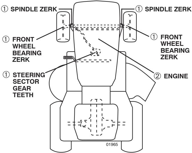
① General Purpose Grease
② Refer to Maintenance “ENGINE” Section
IMPORTANT: DO NOT OIL OR GREASE THE PIVOT POINTS WHICH HAVE SPECIAL NYLON BEARINGS. VISCOUS LUBRICANTS WILL ATTRACT DUST AND DIRT THAT WILL SHORTEN THE LIFE OF THE SELF-LUBRICATING BEARINGS. IF YOU FEEL THEY MUST BE LUBRICATED, USE ONLY A DRY, POWDERED GRAPHITE TYPE LUBRICANT SPARINGLY.
MAINTENANCE
TRACTOR
Always observe safety rules when performing any maintenance.
BRAKE OPERATION
If tractor requires more than five (5) feet to stop at highest speed in highest gear on a level, dry concrete or paved surface, then brake must be checked and adjusted. (See "TO CHECK BRAKE" in the Service and Adjustments section of this manual).
TIRES
- Maintain proper air pressure in all tires (See the sides of tires for proper PSI).
- Keep tires free of gasoline, oil, or insect control chemicals which can harm rubber.
- Avoid stumps, stones, deep ruts, sharp objects and other hazards that may cause tire damage.
NOTE: To seal tire punctures and prevent flat tires due to slow leaks, tire sealant may be purchased from your local parts dealer. Tire sealant also prevents tire dry rot and corrosion.
OPERATOR PRESENCE SYSTEM AND REVERSE OPERATION SYSTEM (ROS) (See Fig. 14)
Be sure operator presence and reverse operation systems are working properly. If your tractor does not function as described, repair the problem immediately.
- The engine should not start unless the brake pedal is fully depressed, and the attachment clutch control is in the disengaged position.
CHECK OPERATOR PRESENCE SYSTEM
- When the engine is running, any attempt by the operator to leave the seat without first setting the parking brake should shut off the engine.
- When the engine is running and the attachment clutch is engaged, any attempt by the operator to leave the seat should shut off the engine.
- The attachment clutch should never operate unless the operator is in the seat.
CHECK REVERSE OPERATION (ROS) SYSTEM
- When the engine is running with the ignition switch in the engine "ON" position and the attachment clutch engaged, any attempt by the operator to shift into reverse should shut off the engine.
- When the engine is running with the ignition switch in the ROS "ON" position and the attachment clutch engaged, any attempt by the operator to shift into reverse should NOT shut off the engine.

ROS "ON" POSITION
ENGINE "ON" POSITION (NORMAL OPERATING)
Fig. 14
BLADE CARE
For best results mower blades must be kept sharp. Replace bent or damaged blades.

CAUTION: Use only a replacement blade approved by the manufacturer of your tractor. Using a blade not approved by the manufacturer of your tractor is hazardous, could damage your tractor and void your warranty.
BLADE REMOVAL (See Fig. 15)
- Raise mower to highest position to allow access to blades.
NOTE: Protect your hands with gloves and/or wrap blade with heavy cloth.
- Remove blade bolt by turning counterclockwise.
• Install new or resharpened blade with stamped "THIS SIDE UP" facing deck and mandrel assembly.
IMPORTANT: TO ENSURE PROPER ASSEMBLY, CENTER HOLE IN BLADE MUST ALIGN WITH STAR ON MANDREL ASSEMBLY.
• Install and tighten blade bolt securely (45-55 Ft. Lbs. torque).
IMPORTANT: SPECIAL BLADE BOLT HEAT TREATED.
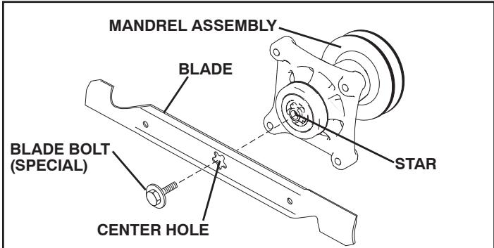
Fig. 15
BATTERY
Your tractor has a battery charging system which is sufficient for normal use. However, periodic charging of the battery with an automotive charger will extend its life.
- Keep battery and terminals clean.
- Keep battery bolts tight.
- Keep small vent holes open.
• Recharge at 6-10 amperes for 1 hour.
NOTE: The original equipment battery on your tractor is maintenance free. Do not attempt to open or remove caps or covers. Adding or checking level of electrolyte is not necessary.
TO CLEAN BATTERY AND TERMINALS
Corrosion and dirt on the battery and terminals can cause the battery to “leak” power.
- Disconnect BLACK battery cable first then RED battery cable and remove battery from tractor.
- Rinse the battery with plain water and dry.
- Clean terminals and battery cable ends with wire brush until bright.
- Coat terminals with grease or petroleum jelly.
- Reinstall battery (See "REPLACING BATTERY" in the SERVICE AND ADJUSTMENTS section of this manual).
MAINTENANCE
V-BELTS
Check V-belts for deterioration and wear after 100 hours of operation and replace if necessary. The belts are not adjustable. Replace belts if they begin to slip from wear.
TRANSAXLE COOLING
The transmission fan and cooling fins should be kept clean to assure proper cooling.
Do not attempt to clean fan or transmission while engine is running or while the transmission is hot. To prevent possible damage to seals, do not use high pressure water or steam to clean transaxle.
- Inspect cooling fan to be sure fan blades are intact and clean.
- Inspect cooling fins for dirt, grass clippings and other materials. To prevent damage to seals, do not use compressed air or high pressure sprayer to clean cooling fins.
TRANSAXLE PUMP FLUID
The transaxle was sealed at the factory and fluid maintenance is not required for the life of the transaxle. Should the transaxle ever leak or require servicing, contact your nearest authorized service center/department.
ENGINE
LUBRICATION
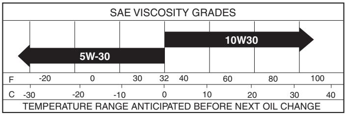
Only use high quality detergent oil rated with API service classification SG-SL. Select the oil's SAE viscosity grade according to your expected operating temperature.
bar
| Grade Range | Value | | ----------- | ----- | | 5W-30 | 5W-30 | | 10W30 | 10W30 |Change the oil after every 50 hours of operation or at least once a year if the tractor is not used for 50 hours in one year.
Check the crankcase oil level before starting the engine and after each eight (8) hours of operation.
TO CHANGE ENGINE OIL (See Fig. 16)
Determine temperature range expected before oil change. All oil must meet API service classification SG-SL.
- Be sure tractor is on level surface.
• Oil will drain more freely when warm.
• Catch oil in a suitable container. - Remove oil fill cap/dipstick. Be careful not to allow dirt to enter the engine when changing oil.
- Remove yellow cap from end of drain valve and install the drain tube onto the fitting.
- Unlock drain valve by pushing inward and turning counterclockwise.
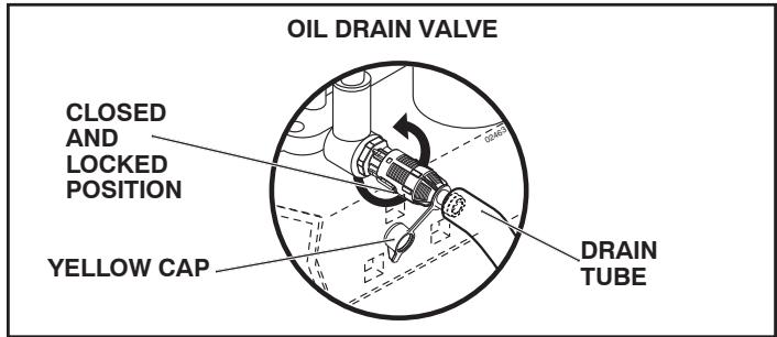
Fig. 16
• To open, pull out on the drain valve.
- After oil has drained completely, close and lock the drain valve by pushing inward and turning clockwise until the pin is in the locked position as shown.
- Remove the drain tube and replace the cap onto to the bottom fitting of the drain valve.
- Refill engine with oil through oil fill dipstick tube. Pour slowly. Do not overfill. For approximate capacity see "PRODUCT SPECIFICATIONS" section of this manual.
- Use gauge on oil fill cap/dipstick for checking level. For accurate reading, insert dipstick into the tube and push down firmly into place before removing. Keep oil up to, but not over, the “FULL” line on dipstick. Push dipstick down firmly into the tube when finished.
ENGINE OIL FILTER
Replace the engine oil filter every season or every other oil change if the tractor is used more than 100 hours in one year. See engine manual.
ENGINE COOLING SYSTEM
To ensure proper cooling, make sure the grass screen, cooling fins, and other external surfaces of the engine are kept clean at all times.
Every 100 hours of operation (more often under extremely dusty, dirty conditions), remove the blower housing and other cooling shrouds. Clean the cooling fins and external surfaces as necessary. Ensure the cooling shrouds are reinstalled.
NOTE: Operating the engine with a blocked grass screen, dirty or plugged cooling fins, and/or cooling shrouds removed will cause engine damage due to overheating.
CLEAN AIR SCREEN
Air screen must be kept free of dirt and chaff to prevent engine damage from overheating. Clean with a wire brush or compressed air to remove dirt and stubborn dried gum fibers.
AIR FILTER
Your engine will not run properly using a dirty air filter. Service air cleaner more often under dusty conditions. See engine manual.
MUFFLER
Inspect and replace corroded muffler and spark arrester (if equipped) as it could create a fire hazard and/or damage.
MAINTENANCE
SPARK PLUGS
Replace spark plugs at the beginning of each mowing season or after every 100 hours of operation, whichever occurs first. Spark plug type and gap setting are shown in "PRODUCT SPECIFICATIONS" section of this manual.
IN-LINE FUEL FILTER (See Fig. 17)
The fuel filter should be replaced once each season. If fuel filter becomes clogged, obstructing fuel flow to carburetor, replacement is required.
- With engine cool, remove filter and plug fuel line sections.
- Place new fuel filter in position in fuel line with arrow pointing towards carburetor.
- Be sure there are no fuel line leaks and clamps are properly positioned.
- Immediately wipe up any spilled gasoline.

Fig. 17
DECK WASHOUT PORT (See Fig. 18)
Your tractor's deck is equipped with a washout port on its surface as part of its deck wash system. It should be utilized after each use.
- Drive the tractor to a level, clear spot on your lawn, near enough to a water spigot for your garden hose to reach.
IMPORTANT: Make certain the tractor's discharge chute is directed AWAY from your house, garage, parked cars, etc. Remove bagger chute or mulch cover if attached.
- Make sure the attachment clutch control is in the "DISENGAGED" position, set the parking brake, and stop the engine.
- Thread the nozzle adapter (packaged with your tractor's Operator's Manual) onto the end of your garden hose.
- Pull back the lock collar of the nozzle adapter and push the adapter onto the deck washout port at the left end of the mower deck. Release the lock collar to lock the adapter on the nozzle.

Fig. 18
IMPORTANT: Tug hose ensuring connection is secure.
- Turn the water on.
- While sitting in the operator's position on the tractor, re-start the engine and place the throttle lever in the Fast "💡" position.
IMPORTANT: Recheck the area making certain the area is clear.
- Move the tractor's attachment clutch control to the "ENGAGED" position. Remain in the operator's position with the cutting deck engaged until the deck is cleaned.
- Move the tractor's attachment clutch control to the "DISENGAGED" position. Turn the ignition key to the STOP position to turn the tractor's engine off. Turn the water off.
- Pull back the lock collar of the nozzle adapter to disconnect the adapter from the nozzle washout port.
- Move the tractor to a dry area, preferably a concrete or paved area. Place the attachment clutch control in the "ENGAGED" position to remove excess water and to help dry before putting the tractor away.

WARNING: A broken or missing washout fitting could expose you or others to thrown objects from contact with the blade.
- Replace broken or missing washout fitting immediately, prior to using mower again.
• Plug any holes in mower with bolts and locknuts.
CLEANING
- Clean engine, battery, seat, finish, etc. of all foreign matter.
- Clean debris from steering plate. Debris can restrict clutch/brake pedal shaft movement, causing belt slip and loss of drive.

CAUTION: Avoid all pinch points and movable parts (See Fig. 19)
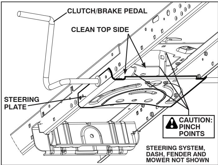
Fig. 19
- Keep finished surfaces and wheels free of all gasoline, oil, etc.
- Protect painted surfaces with automotive type wax.
We do not recommend using a garden hose or pressure washer to clean your tractor unless the engine and transmission are covered to keep water out. Water in engine or transmission will shorten the useful life of your tractor. Use compressed air or a leaf blower to remove grass, leaves and trash from tractor and mower.
SERVICE AND ADJUSTMENTS

WARNING: TO AVOID SERIOUS INJURY, BEFORE PERFORMING ANY SERVICE OR ADJUSTMENTS:
- Depress brake pedal fully and set parking brake.
- Place attachment clutch in “DISENGAGED” position.
- Turn ignition key to "STOP" and remove key.
• Make sure the blades and all moving parts have completely stopped. - Disconnect spark plug wire from spark plug and place wire where it cannot come in contact with plug.
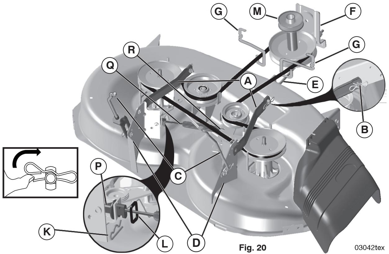
TO REMOVE MOWER (See Fig. 20)
- Place attachment clutch in "DISENGAGED" position.
• Lower attachment lift lever to its lowest position.
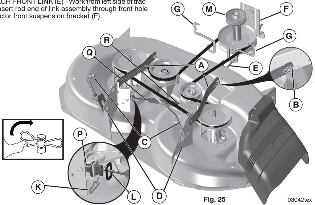
• Roll belt off engine pulley (M) and belt keepers (G). - Remove retainer spring (K), slide collar (L) off and push housing guide (P) out of bracket.
- Remove clutch cable spring (Q) from idler arm (R).
- Disconnect front link (E) from mower - remove retainer spring and washer.
- Go to either side of mower and disconnect mower suspension arm (A) from chassis pin (B) and rear lift link (C) from rear mower bracket (D) - remove retainer springs and washers.

CAUTION: AFTER REAR LIFT LINKS ARE DISCONNECTED, THE ATTACHMENT LIFT LEVER WILL BE SPRING LOADED. HAVE A TIGHT GRIP ON LIFT LEVER WHEN CHANGING POSITION OF THE LEVER.
- Slide mower out from under right side of tractor.
IMPORTANT: IF AN ATTACHMENT OTHER THAN THE MOWER IS TO BE MOUNTED ON THE TRACTOR, REMOVE THE FRONT LINK (E) AND REAR LIFT LINKS (C) FROM TRACTOR AND HOOK THE CLUTCH SPRING (Q) INTO THE CABLE GUIDE ON FRONT EDGE OF LOWER DASH.
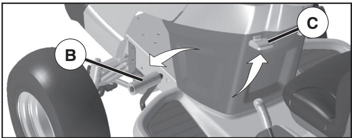
TO INSTALL MOWER (See Fig. 21-25)
Be sure tractor is on level surface and engage parking brake.
• Lower attachment lift lever to its lowest position.

CAUTION: LIFT LEVER IS SPRING LOADED. HAVE A TIGHT GRIP ON LIFT LEVER, LOWER IT SLOWLY AND ENGAGE IN LOWEST POSITION.
NOTE: Be sure mower side suspension arms (A) are pointing forward before sliding mower under tractor.
- Slide mower under tractor until it is centered under tractor.
SERVICE AND ADJUSTMENTS
- ATTACH MOWER SIDE SUSPENSION ARMS (A) TO CHASSIS - Position hole in arm over pin (B) on outside of tractor chassis and secure with retainer spring.
- Repeat on opposite side of tractor.
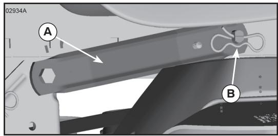
Fig. 21
- ATTACH REAR LIFT LINKS (C) - Lift rear corner of mower and position slot in link assembly over pin (D) on rear mower bracket and secure with washer and retainer spring.
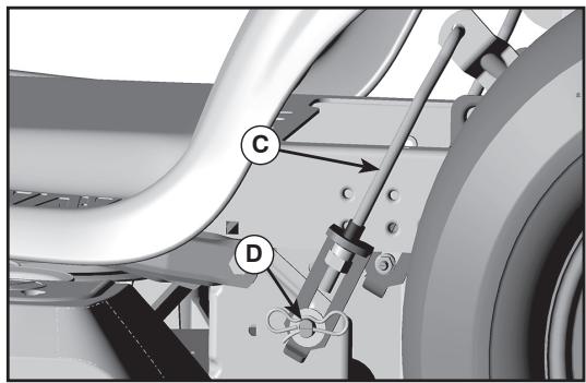
Fig. 22
- ATTACH FRONT LINK (E) - Work from left side of tractor. Insert rod end of link assembly through front hole in tractor front suspension bracket (F).
- Insert end of link (E) into hole in front mower bracket and secure with washer and retainer spring (J).
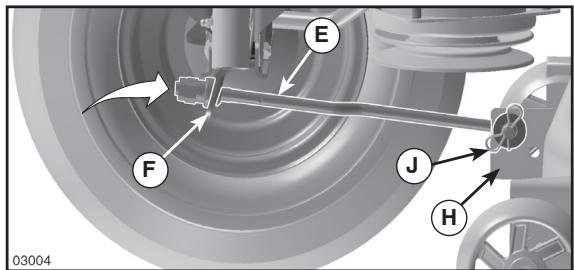
Fig. 23
- Hook end of clutch cable spring (Q) into hole in idler arm (R).
- Push clutch cable housing guide (P) into bracket, slide collar (L) onto guide and secure with retainer spring (K).
• Install belt on engine pulley (M), in belt keepers (G).
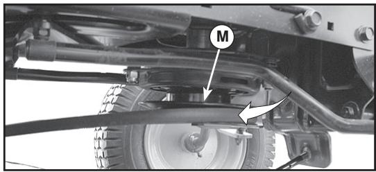
Fig. 24
IMPORTANT: CHECK BELT FOR PROPER ROUTING IN ALL MOWER PULLEY GROOVES.
- Raise attachment lift lever to highest position.
- If necessary, adjust gauge wheels before operating mower as shown in the Operation section of this manual.
SERVICE AND ADJUSTMENTS
TO LEVEL MOWER
Make sure tires are properly inflated to the PSI shown on tires. If tires are over or under inflated, it may affect the appearance of your lawn and lead you to think the mower is not adjusted properly.
VISUAL SIDE-TO-SIDE ADJUSTMENT (See Fig. 26)
- With all tires properly inflated and if your lawn appears unevenly cut, determine which side of mower is cutting lower.
- With a 3/4" or adjustable wrench, turn lift link adjustment nut (A) to the left to lower LH side of mower, or, to the right to raise LH side of mower.
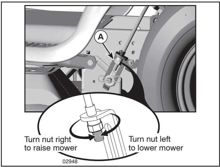
Fig. 26
NOTE: Each full turn of adjustment nut will change mower height about 3/16".
- Test your adjustment by mowing some uncut grass and visually checking the appearance. Readjust, if necessary, until you are satisfied with the results.
PRECISION SIDE-TO-SIDE ADJUSTMENT (See Fig. 27)
- With all tires properly inflated, park tractor on level ground or driveway.

CAUTION: Blades are sharp. Protect your hands with gloves and/or wrap blade with heavy cloth.
- Raise mower to its highest position.
- At both sides of mower, position blade at side and measure the distance (A) from bottom edge of blade to the ground. The distance should be the same on both sides.
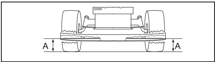
FIG. 27
- If adjustment is necessary, see step in Visual Adjustment instructions above.
- Recheck measurements, adjust if necessary until both sides are equal.
FRONT-TO-BACK ADJUSTMENT (See Figs. 28 & 29)
IMPORTANT: Deck must be level side-to-side.
To obtain the best cutting results, the mower blades should be adjusted so the front tip is 1/8" to 1/2" lower than the rear tip when the mower is in its highest position.

CAUTION: Blades are sharp. Protect your hands with gloves and/or wrap blade with heavy cloth.
- Raise mower to highest position.
- Position any blade so the tip is pointing straight forward. Measure distance (B) to the ground at front and rear tip of the blade.
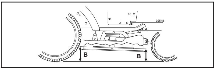
Fig. 28
- If front tip of blade is not 1/8" to 1/2" lower than the rear tip, go to the front of tractor.
- With an 11/16" or adjustable wrench, loosen jam nut A several turns to clear adjustment nut B.
- With a 3/4" or adjustable wrench, turn front link adjustment nut (B) clockwise (ltighten) to raise the front of mower, or, counterclockwise (loosen) to lower the front mower.
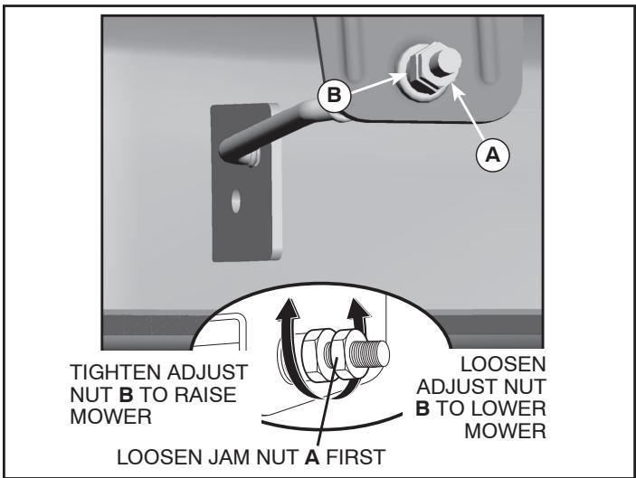
Fig. 29
NOTE: Each full turn of the adjustment nut will change mower height about 1/8".
- Recheck measurements, adjust if necessary until front tip of blade is 1/8" to 1/2" lower than the rear tip.
- Hold adjustment nut in position with wrench and tighten jam nut securely against adjustment nut.
SERVICE AND ADJUSTMENTS
TO REPLACE MOWER BLADE DRIVE BELT (See Fig. 30)
The mower blade drive belt may be replaced without tools. Park the tractor on level surface. Engage parking brake.
BELT REMOVAL -
- Remove mower from tractor (See “TO REMOVE MOWER” in this section of manual).
• Work belt off both mandrel pulleys and idler pulleys.
• Pull belt away from mower.
BELT INSTALLATION -
• Work belt around both mandrel pulleys and idler pulleys.
- Make sure belt is in all pulley grooves and inside all belt guides.
• Install mower (See "To Install Mower" in this section of manual).
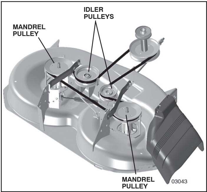
Fig. 30
TO CHECK BRAKE
If tractor requires more than five (5) feet to stop at highest speed in highest gear on a level, dry concrete or paved surface, then brake must be serviced.
You may also check brake by:
- Park tractor on a level, dry concrete or paved surface, depress brake pedal all the way down and engage parking brake.
- Disengage transmission by placing freewheel control in “transmission disengaged” position. Pull freewheel control out and into the slot and release so it is held in the disengaged position.
The rear wheels must lock and skid when you try to manually push the tractor forward. If the rear wheels rotate, then the brake needs to be serviced. Contact a qualified service center.
TO REPLACE MOTION DRIVE BELT (See Fig. 31)
Park the tractor on level surface. Engage parking brake. For assistance, there is a belt installation guide decal on bottom side of left footrest.
BELT REMOVAL -
- Remove mower (See "TO REMOVE MOWER" section in this manual).
NOTE: Observe entire motion drive belt and position of all belt guides and keepers.
- Remove belt from stationary idler (A) and clutching idler (B).
- Remove belt from centerspan idler (C).
- Pull belt slack toward rear of tractor. Remove belt upwards from transaxle input pulley (D).
- Remove belt downward from engine pulley (E).
- Slide belt toward rear of tractor, off the steering plate (F) and remove from tractor.
BELT INSTALLATION -
- Install new belt from tractor rear to front, over the steering plate (F) and above clutch brake pedal shaft (G).
- Pull belt toward front of tractor and roll belt onto engine pulley (E).
- Pull belt toward rear of tractor. Carefully work belt down around transaxle input pulley (D). Be sure belt is inside the belt keeper.
- Install belt on centerspan idler (C).
- Install belt through stationary idler (A) and clutching idler (B).
- Make sure belt is in all pulley grooves and inside all belt guides and keepers.
- Install mower (See "TO INSTALL MOWER" section in this manual).
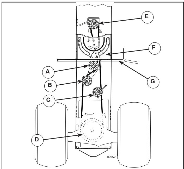
Fig. 31
SERVICE AND ADJUSTMENTS
FRONT WHEEL TOE-IN/CAMBER
Your new tractor front wheel toe-in and camber is set at the factory and is normal. The front wheel toe-in and camber are not adjustable. If damage has occurred to affect the factory set front wheel toe-in or camber, contact a qualified service center.
TO REMOVE WHEEL FOR REPAIRS (See Fig. 32)
• Block up axle securely.
- Remove axle cover, retaining ring and washers to allow wheel removal (rear wheel contains a square key - Do not lose).
• Repair tire and reassemble.
- On rear wheels only: align grooves in rear wheel hub and axle. Insert square key.
- Replace washers and snap retaining ring securely in axle groove.
- Replace axle cover.
NOTE: To seal tire punctures and prevent flat tires due to slow leaks, tire sealant may be purchased from your local parts dealer. Tire sealant also prevents tire dry rot and corrosion.
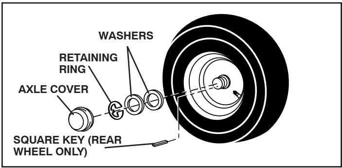
Fig. 32
TO START ENGINE WITH A WEAK BATTERY (See Fig. 33)

WARNING: Lead-acid batteries generate explosive gases. Keep sparks, flame and smoking materials away from batteries. Always wear eye protection when around batteries.
If your battery is too weak to start the engine, it should be recharged. (See "BATTERY" in the MAINTENANCE section of this manual).
If “jumper cables” are used for emergency starting, follow this procedure:
IMPORTANT: YOUR TRACTOR IS EQUIPPED WITH A 12 VOLT SYSTEM. THE OTHER VEHICLE MUST ALSO BE A 12 VOLT SYSTEM. DO NOT USE YOUR TRACTOR BATTERY TO START OTHER VEHICLES.
TO ATTACH JUMPER CABLES -
- Connect one end of the RED cable to the POSITIVE (+) terminal of each battery(A-B), taking care not to short against tractor chassis.
- Connect one end of the BLACK cable to the NEGATIVE (-) terminal (C) of fully charged battery.
- Connect the other end of the BLACK cable (D) to good chassis ground, away from fuel tank and battery.
TO REMOVE CABLES, REVERSE ORDER -
- BLACK cable first from chassis and then from the fully charged battery.
• RED cable last from both batteries.

Fig. 33
REPLACING BATTERY (See Fig. 34)

WARNING: Do not short battery terminals by allowing a wrench or any other object to contact both terminals at the same time. Before connecting battery, remove metal bracelets, wristwatch bands, rings, etc. Positive terminal must be connected first to prevent sparking from accidental grounding.
- Lift seat pan to raised position.
- Disconnect BLACK battery cable first then RED battery cable and carefully remove battery from tractor.
• Install new battery with terminals in same position as old battery. - First connect RED battery cable to positive (+) terminal with bolt and nut as shown. Tighten securely. Slide terminal cover over terminal.
- Connect BLACK grounding cable to negative (-) terminal with remaining bolt and nut. Tighten securely.
- Lower seat pan.
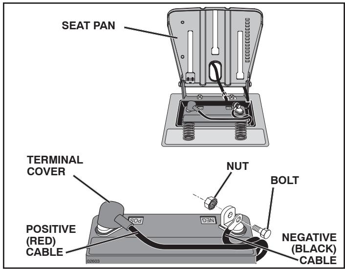
Fig. 34
SERVICE AND ADJUSTMENTS
TO REPLACE HEADLIGHT BULB
- Raise hood.
- Pull bulb holder out of the hole in the backside of the grill.
- Replace bulb in holder and push bulb holder securely back into the hole in the backside of the grill.
- Close hood.
INTERLOCKS AND RELAYS
Loose or damaged wiring may cause your tractor to run poorly, stop running, or prevent it from starting.
- Check wiring. See electrical wiring diagram in the Repair Parts section.
TO REPLACE FUSE
Replace with 20 amp automotive-type plug-in fuse. The fuse holder is located behind the dash.
TO REMOVE HOOD AND GRILL ASSEMBLY (See Fig. 35)
- Raise hood.
• Unsnap headlight wire connector. - Stand in front of tractor. Grasp hood at sides, tilt toward engine and lift off of tractor.
• To replace, reverse above procedure.
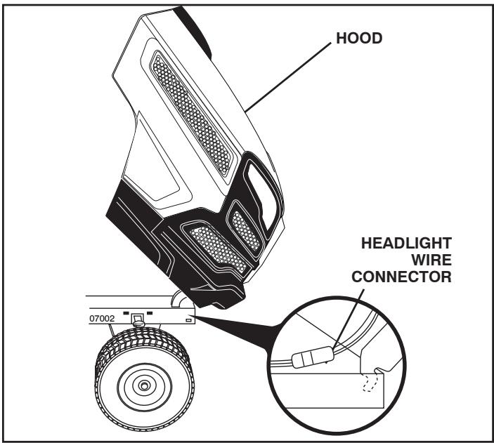
Fig. 35
ENGINE
TO ADJUST THROTTLE CONTROL CABLE
The throttle control has been preset at the factory and adjustment should not be necessary. If adjustment is necessary, see engine manual.
TO ADJUST CHOKE CONTROL
The choke control has been preset at the factory and adjustment should not be necessary. If adjustment is necessary, see engine manual.
TO ADJUST CARBURETOR
Your carburetor is not adjustable. If your engine does not operate properly due to suspected carburetor problems, take your tractor to an authorized service center for repair and/or adjustment.
TRANSMISSION
REMOVAL/REPLACEMENT
Should your transmission require removal for service or replacement, it should be purged after reinstallation and before operating the tractor. See "PURGETRANSMISSION" in the Operation section of this manual.
Immediately prepare your tractor for storage at the end of the season or if the tractor will not be used for 30 days or more.

WARNING: Never store the tractor with gasoline in the tank inside a building where fumes may reach an open flame or spark. Allow the engine to cool before storing in any enclosure.
TRACTOR
Remove mower from tractor for winter storage. When mower is to be stored for a period of time, clean it thoroughly, remove all dirt, grease, leaves, etc. Store in a clean, dry area.
- Clean entire tractor (See “CLEANING” in the Maintenance section of this manual).
- Inspect and replace belts, if necessary (See belt replacement instructions in the Service and Adjustments section of this manual).
- Lubricate as shown in the Maintenance section of this manual.
- Be sure that all nuts, bolts and screws are securely fastened. Inspect moving parts for damage, breakage and wear. Replace if necessary.
- Touch up all rusted or chipped paint surfaces; sand lightly before painting.
BATTERY
• Fully charge the battery for storage.
• After a period of time in storage, battery may require recharging.
- To help prevent corrosion and power leakage during long periods of storage, battery cables should be disconnected and battery cleaned thoroughly (see "TO CLEAN BATTERY AND TERMINALS" in the Maintenance section of this manual).
- After cleaning, leave cables disconnected and place cables where they cannot come in contact with battery terminals.
- If battery is removed from tractor for storage, do not store battery directly on concrete or damp surfaces.
ENGINE
FUEL SYSTEM
IMPORTANT: IT IS IMPORTANT TO PREVENT GUM DEPOSITS FROM FORMING IN ESSENTIAL FUEL SYSTEM PARTS SUCH AS CARBURETOR, FUEL FILTER, FUEL HOSE, OR TANK DURING STORAGE. ALSO, EXPERIENCE INDICATES THAT ALCOHOL BLENDED FUELS (CALLED GASOHOL OR USING ETHANOL OR METHANOL) CAN ATTRACT MOISTURE WHICH LEADS TO SEPARATION AND FORMATION OF ACIDS DURING STORAGE. ACIDIC GAS CAN DAMAGE THE FUEL SYSTEM OF AN ENGINE WHILE IN STORAGE.
• Empty the fuel tank by starting the engine and let it run until the fuel lines and carburetor are empty.
- Never use engine or carburetor cleaner products in the fuel tank or permanent damage may occur.
• Use fresh fuel next season.
NOTE: Fuel stabilizer is an acceptable alternative in minimizing the formation of fuel gum deposits during storage. Add stabilizer to gasoline in fuel tank or storage container. Always follow the mix ratio found on stabilizer container. Run engine at least 10 minutes after adding stabilizer to allow the stabilizer to reach the carburetor. Do not empty the gas tank and carburetor if using fuel stabilizer.
ENGINE OIL
Drain oil (with engine warm) and replace with clean engine oil. (See “ENGINE” in the Maintenance section of this manual).
CYLINDER(S)
- Remove spark plug(s).
- Pour one ounce of oil through spark plug hole(s) into cylinder(s).
- Turn ignition key to "START" position for a few seconds to distribute oil.
- Replace with new spark plug(s).
OTHER
- Do not store gasoline from one season to another.
- Replace your gasoline can if your can starts to rust. Rust and/or dirt in your gasoline will cause problems.
- If possible, store your tractor indoors and cover it to give protection from dust and dirt.
- Cover your tractor with a suitable protective cover that does not retain moisture. Do not use plastic. Plastic cannot breathe which allows condensation to form and will cause your tractor to rust.
IMPORTANT: NEVER COVER TRACTOR WHILE ENGINE AND EXHAUST AREAS ARE STILL WARM.
TROUBLESHOOTING POINTS
| PROBLEM | CAUSE | CORRECTION |
| Will not start | 1. Out of fuel.2. Engine not “CHOKED” properly.3. Engine flooded.4. Bad spark plug.5. Dirty air filter.6. Dirty fuel filter.7. Water in fuel.8. Loose or damaged wiring.9. Carburetor out of adjustment.10. Engine valves out of adjustment. | 1. Fill fuel tank.2. See “TO START ENGINE” in Operation section.3. Wait several minutes before attempting to start.4. Replace spark plug.5. Clean/replace air filter.6. Replace fuel filter.7. Empty fuel tank and carburetor, refill tank with fresh gasoline and replace fuel filter.8. Check all wiring.9. See “To Adjust Carburetor” in Service Adjustments section.10. Contact an authorized service center/department. |
| Hard to start | 1. Dirty air filter.2. Bad spark plug.3. Weak or dead battery.4. Dirty fuel filter.5. Stale or dirty fuel.6. Loose or damaged wiring.7. Carburetor out of adjustment.8. Engine valves out of adjustment. | 1. Clean/replace air filter.2. Replace spark plug.3. Recharge or replace battery.4. Replace fuel filter.5. Empty fuel tank and refill tank with fresh, clean gas.6. Check all wiring.7. See “To Adjust Carburetor” in Service Adjustments section.8. Contact an authorized service center/department. |
| Engine will not turn over | 1. Brake pedal not depressed.2. Attachment clutch is engaged.3. Weak or dead battery.4. Blown fuse.5. Corroded battery terminals.6. Loose or damaged wiring.7. Faulty ignition switch.8. Faulty solenoid or starter.9. Faulty operator presence switch(es). | 1. Depress brake pedal.2. Disengage attachment clutch.3. Recharge or replace battery.4. Replace fuse.5. Clean battery terminals.6. Check all wiring.7. Check/replace ignition switch.8. Check/replace solenoid or starter.9. Contact an authorized service center/department. |
| Engine clicks but will not start | 1. Weak or dead battery.2. Corroded battery terminals.3. Loose or damaged wiring.4. Faulty solenoid or starter. | 1. Recharge or replace battery.2. Clean battery terminals.3. Check all wiring.4. Check/replace solenoid or starter. |
| Loss of power | 1. Cutting too much grass/too fast.2. Throttle in “CHOKE” position.3. Build-up of grass, leaves, trash under mower.4. Dirty air filter.5. Low oil level/dirty oil.6. Faulty spark plug.7. Dirty fuel filter.8. Stale or dirty fuel.9. Water in fuel.10. Spark plug wire loose.11. Dirty engine air screen/fins.12. Dirty/clogged muffler.13. Loose or damaged wiring.14. Carburetor out of adjustment.15. Engine valves out of adjustment. | 1. Raise cutting height/reduce speed.2. Adjust throttle control.3. Clean underside of mower housing.4. Clean/replace air filter.5. Check oil level/change oil.6. Clean and regap or change spark plug.7. Replace fuel filter.8. Empty fuel tank and refill tank with fresh, clean gas.9. Empty fuel tank and carburetor, refill tank with fresh gasoline and replace fuel filter.10. Connect and tighten spark plug wire.11. Clean engine air screen/fins.12. Clean/replace muffler.13. Check all wiring.14. See “To Adjust Carburetor” in Service Adjustments 15. Contact an authorized service center/department. |
| Excessive vibration | 1. Worn, bent or loose blade.2. Bent blade mandrel.3. Loose/damaged part(s). | 1. Replace blade. Tighten blade bolt.2. Replace blade mandrel.3. Tighten loose part(s). Replace damaged parts. |
TROUBLESHOOTING POINTS
| PROBLEM | CAUSE | CORRECTION |
| Engine continues to run when operator leaves seat with attachment clutch engaged | 1. Faulty operator-safety presence control system. | 1. Check wiring, switches and connections. If not corrected, contact an authorized service center/department. |
| Poor cut - uneven | 1. Worn, bent or loose blade.2. Mower deck not level.3. Buildup of grass, leaves, trash under mower.4. Bent blade mandrel.5. Clogged mower deck vent holes from buildup of grass, leaves, and trash around mandrels. | 1. Replace blade. Tighten blade bolt.2. Level mower deck.3. Clean underside of mower housing.4. Replace blade mandrel.5. Clean around mandrels to open vent holes. |
| Mower blades will not rotate | 1. Obstruction in clutch mechanism.2. Worn/damaged mower drive belt.3. Frozen idler pulley.4. Frozen blade mandrel. | 1. Remove obstruction.2. Replace mower drive belt.3. Replace idler pulley.4. Replace blade mandrel. |
| Poor grass discharge | 1. Engine speed too slow.2. Travel speed too fast.3. Wet grass.4. Mower deck not level.5. Low/uneven tire air pressure.6. Worn, bent or loose blade.7. Buildup of grass, leaves, trash under mower.8. Mower drive belt worn.9. Blades improperly installed.10. Improper blades used.11. Clogged mower deck vent holes from buildup of grass, leaves, trash around mandrels. | 1. Place throttle control in “FAST” position.2. Shift to slower speed.3. Allow grass to dry before mowing.4. Level mower deck.5. Check tires for proper air pressure.6. Replace blade. Tighten blade bolt.7. Clean underside of mower housing.8. Replace mower drive belt.9. Reinstall blades sharp edge down.10. Replace with blades listed in parts manual.11. Clean around mandrels to open vent holes. |
| Headlight(s) not working (if so equipped) | 1. Switch is “OFF”.2. Bulb(s) or lamp(s) burned out.3. Faulty light switch.4. Loose or damaged wiring.5. Blown fuse. | 1. Turn switch “ON”.2. Replace bulb(s) or lamp(s).3. Check/replace light switch.4. Check wiring and connections.5. Replace fuse. |
| Battery will not charge | 1. Bad battery cell(s).2. Poor cable connections.3. Faulty regulator (if so equipped).4. Faulty alternator. | 1. Replace battery.2. Check/clean all connections.3. Replace regulator.4. Replace alternator. |
| Loss of drive | 1. Freewheel control in “disengaged” position.2. Debris on steering plate (if equipped).3. Motion drive belt worn, damaged, or broken.4. Air trapped in transmission during shipment or servicing.5. Axle key missing. | 1. Place freewheel control in “engaged” position.2. See “CLEANING” in the maintenance section.3. Replace motion drive belt.4. Purge transmission.5. Install axle key at rear wheel. See "TO REMOVE WHEEL" in the Service and Adjustments section. |
| Engine “back-fires” when turning engine “OFF” | 1. Engine throttle control not set between half and full speed (fast) position before stopping engine. | 1. Move throttle control between half and full speed (fast) position before stopping engine. |
| Engine dies when tractor is shifted into reverse | 1. Reverse operation system (ROS) is not “ON” while mower or other attachment is engaged. | 1. Turn ignition key to ROS “ON” position. See Operation section. |
TRACTOR -- MODEL NUMBER 917.240462, PRODUCT NO. YTH20K46 SCHEMATIC
SCH10
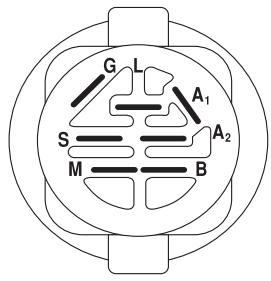
IGNITION SWITCH
| POSITION | CIRCUIT | “MAKE” |
| OFF | M+G+A1 | |
| RUN/OVERRIDE | B+A1 | |
| RUN | B+A1 | L+A2 |
| START | B + S + A1 |
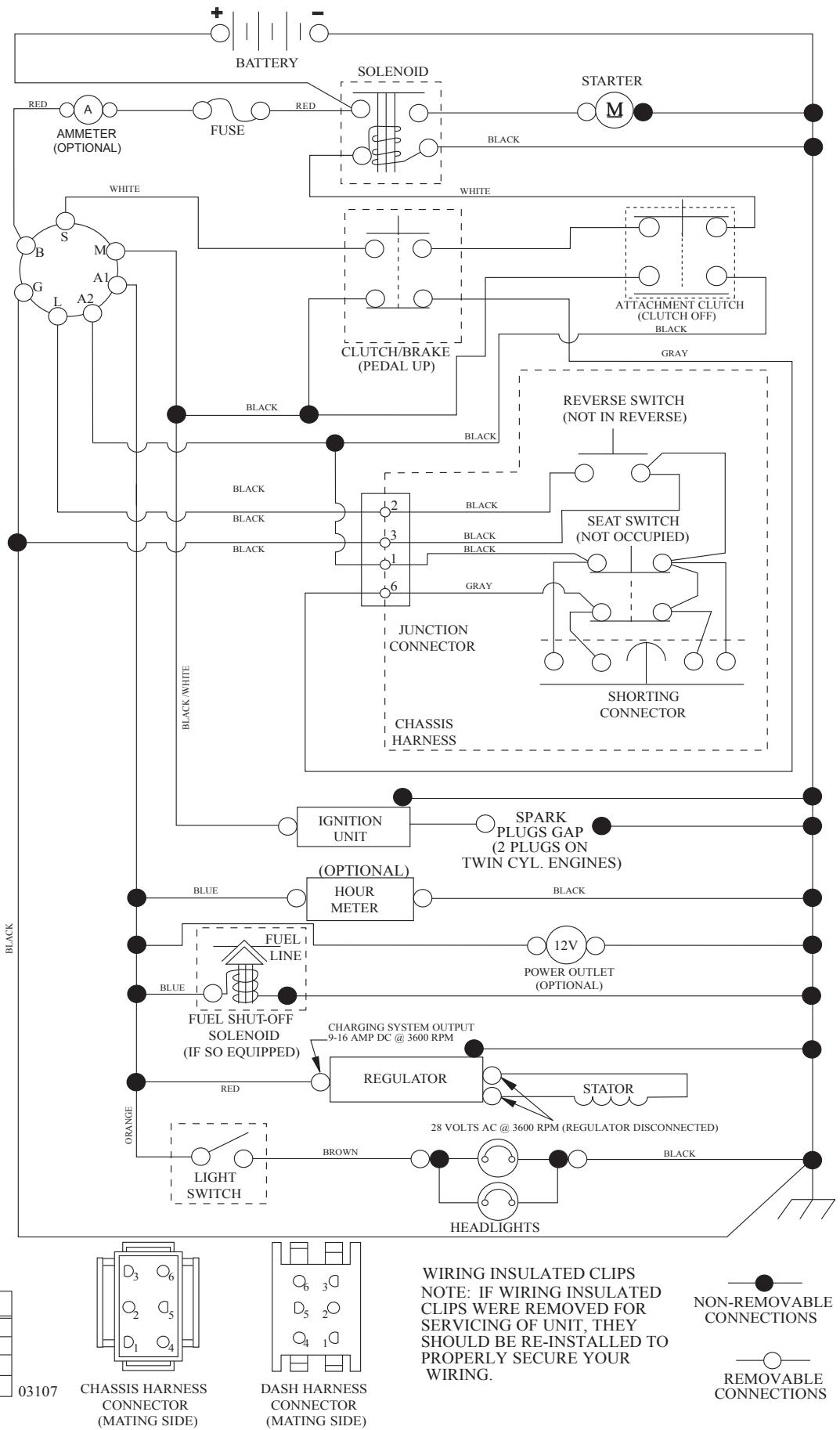
flowchart
graph TD
    A["CHASSIS HARNESS CONNECTOR (MATING SIDE)"] --> B["AMMETER (OPTIONAL)"]
    B --> C["FUSE"]
    C --> D["SOLENOID"]
    D --> E["STARTER M"]
    D --> F["WHITE"]
    F --> G["CLUTCH/BRAKE (PEDAL UP)"]
    G --> H["REVERSE SWITCH (NOT IN REVERSE)"]
    H --> I["SEAT SWITCH (NOT OCCUPIED)"]
    I --> J["SHORTING CONNECTOR"]
    J --> K["JUNCTION CONNECTOR"]
    K --> L["CHASSIS HARNESS"]
    L --> M["IGNITION UNIT"]
    M --> N["SPARK PLUGS GAP (2 PLUGS ON TWIN CYL. ENGINES)"]
    N --> O["(OPTIONAL) HOUR METER"]
    O --> P["FUEL LINE"]
    P --> Q["FUEL SHUT-OFF SOLENOID (IF SO EQUIPPED)"]
    Q --> R["CHARGING SYSTEM OUTPUT 9-16 AMP DC @ 3600 RPM"]
    R --> S["REGULATOR"]
    S --> T["STATOR"]
    T --> U["28 VOLTS AC @ 3600 RPM (REGULATOR DISCONNECTED)"]
    U --> V["BROWN"]
    V --> W["LIGHT SWITCH"]
    W --> X["HEADLIGHTS"]
    X --> Y["BATTERY"]

    subgraph Black
        Z["03107"] --> AA["CHASSIS HARNESS CONNECTOR (MATING SIDE)"]
        AB["DASH HARNESS CONNECTOR (MATING SIDE)"]
        AC["WIRING INSULATED CLIPS NOTE: IF WIRING INSULATED CLIPS WERE REMOVED FOR SERVICING OF UNIT, THEY SHOULD BE RE-INSTALLED TO PROPERLY SECURE YOUR WIRING."]
        AD["NON-REMOVABLE CONNECTIONS"] --> AE["REMOVABLE CONNECTIONS"]
    end
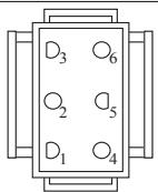
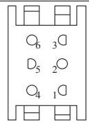

TRACTOR -- MODEL NUMBER 917.240462, PRODUCT NO. YTH20K46 ELECTRICAL
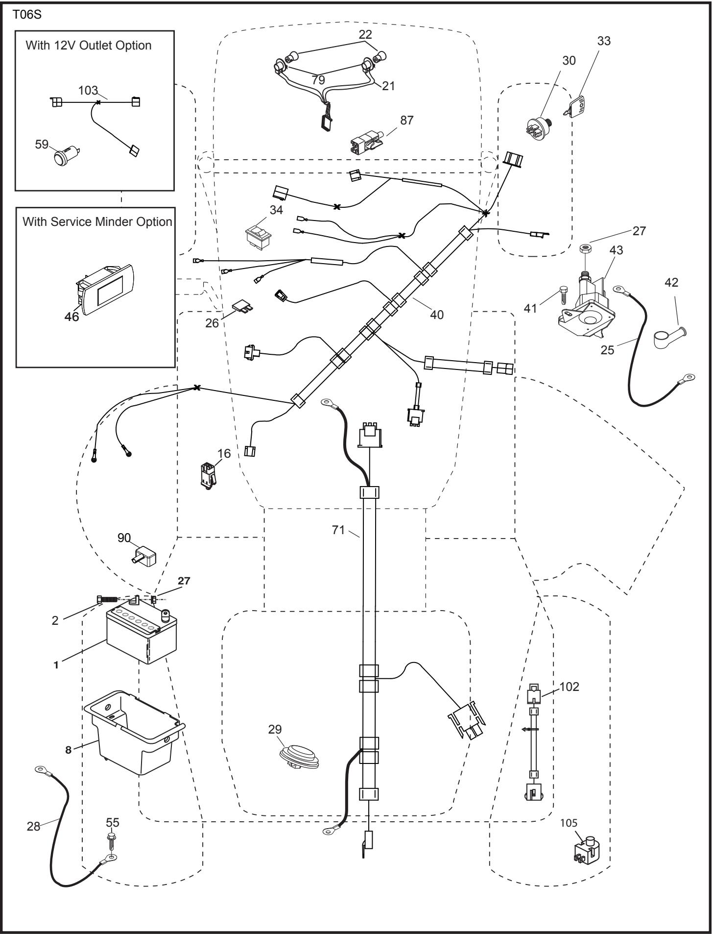
TRACTOR -- MODEL NUMBER 917.240462, PRODUCT NO. YTH20K46 ELECTRICAL
| KEYNO. | PARTNO. | DESCRIPTION |
| 1 | 532 16 34-65 | Battery |
| 2 | 874 76 04-12 | Bolt Hex Head 1/4-20 x 3/4 |
| 8 | 532 19 32-28 | Box Battery |
| 16 | 532 17 61-38 | Switch Interlock Push-In |
| 21 | 532 40 02-52 | Harness Socket Light w/4152J |
| 22 | 532 00 41-52 | Bulb Light |
| 25 | 532 41 28-95 | Cable Starter |
| 26 | 532 17 51-58 | Fuse |
| 27 | 873 51 04-00 | Nut Keps Hex 1/4-20 unc |
| 28 | 532 19 88-85 | Cable, Ground |
| 29 | 532 40 15-45 | Switch, Seat |
| 30 | 532 19 33-50 | Switch, Ign |
| 33 | 532 41 19-33 | Key / Chain |
| 34 | 532 11 07-12 | Switch Light / Reset |
| 40 | 532 40 10-98 | Harness Ign. Dash |
| 41 | 817 72 04-08 | Screw Thd Cut 1/4-20 x 1/2 |
| 42 | 532 13 15-63 | Cover, Terminal |
| 43 | 532 19 25-07 | Solenoid |
| 46 | 532 40 17-63 | Gauge Hourmeter |
| 55 | 817 06 05-12 | Screw Thdrol 5/16-18 x 3/4 TYTT |
| 71 | 532 44 15-44 | Harness Chassis |
| 79 | 532 17 52-42 | Socket Asm. Bulb Twistlock |
| 87 | 532 19 78-02 | Switch Interlock Clutch Cable |
| 90 | 532 43 53-95 | Cover Terminal |
| 102 | 532 40 44-54 | Harness Pigtail |
| 105 | 532 40 75-68 | Switch Reverse TT GT |
NOTE: All component dimensions given in U.S. inches 1 inch = 25.4 mm
TRACTOR -- MODEL NUMBER 917.240462, PRODUCT NO. YTH20K46 CHASSIS
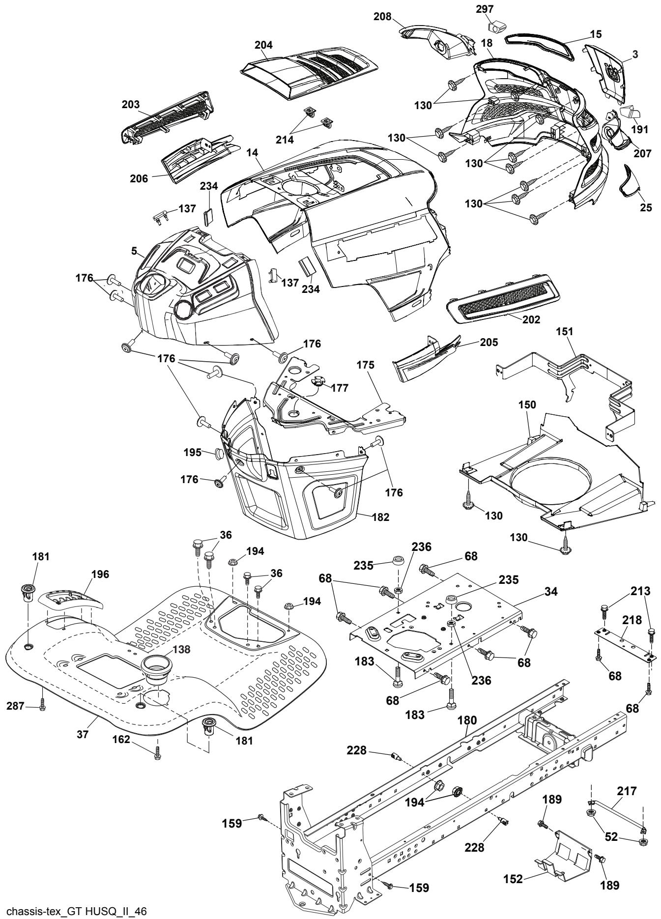
chassis-tex_GT HUSQ_II_46
TRACTOR -- MODEL NUMBER 917.240462, PRODUCT NO. YTH20K46 CHASSIS
| KEYNO. | PARTNO. | DESCRIPTION |
| 3 | 532 43 97-52 | Logo Crown |
| 5 | 532 43 74-73 | Dash |
| 14 | 532 44 11-77 | Hood |
| 15 | 532 43 97-33 | Lens LH |
| 18 | 532 43 77-62 | Grille/Lens Asm. |
| 25 | 532 44 33-85 | Lens RH |
| 34 | 532 19 61-25 | Plate Engine |
| 36 | 817 06 05-12 | Screw 5/16-18 x 3/4 |
| 37 | 532 44 12-06 | Fender |
| 52 | 873 68 05-00 | Nut Lock 5/16-18 |
| 68 | 817 49 05-08 | Screw Thdrol 5/16-18 x 1/2 |
| 130 | 532 41 63-58 | Screw #10 x 0.750 BOS Thread |
| 137 | 532 40 75-90 | Bumper Dash |
| 138 | 532 43 97-47 | Cupholder |
| 150 | 532 43 97-31 | Air Duct |
| 151 | 532 43 66-70 | Bracket Pivot Hood |
| 152 | 532 19 95-35 | Shield Browning |
| 159 | 817 00 06-12 | Screw Hexwsh Thdr 3/8-16 x 3/4 |
| 162 | 532 14 24-32 | Screw |
| 175 | 532 19 63-04 | Crossmember |
| 176 | 532 40 07-76 | Screw 10-24 x 5/8 |
| 177 | 532 19 52-27 | Bushing Steering |
| 180 | 532 19 54-57 | Chassis |
| 181 | 532 40 47-96 | Bushing Mtg. Fender Crgo |
| 182 | 532 40 68-59 | Dash Lower |
| 183 | 874 52 05-20 | Bolt 5/16-18 x 1-1/4 Full Thread |
| 189 | 817 00 05-12 | Screw 5/16-18 x 3/4 |
| 191 | 532 43 74-55 | Insert Reflective RH |
| 194 | 873 90 05-00 | Nut Lock Hex Flange 5/16-18 |
| 195 | 532 40 41-37 | Plug Hole Dash Lower |
| 196 | 532 43 96-47 | Console Asm. Deck Lift |
| 202 | 532 43 97-28 | Vent Side Hood RH |
| 203 | 532 43 97-27 | Vent Side Hood LH |
| 204 | 532 43 57-14 | Vent Top Hood |
| 205 | 532 43 97-30 | Skirt Hood Side RH |
| 206 | 532 43 97-29 | Skirt Hood Side LH |
| 207 | 532 43 97-34 | Bezel RH |
| 208 | 532 43 97-35 | Bezel LH |
| 213 | 874 76 05-12 | Bolt 5/16-18 x 3/4 |
| 214 | 532 19 91-45 | Clip Retainer Tinner |
| 217 | 532 40 91-67 | Rod Pivot |
| 218 | 532 19 63-95 | X-Piece Hood Stop |
| 228 | 532 19 51-61 | Stud Fastner |
| 234 | 532 40 47-42 | Bumper Hood |
| 235 | 532 40 61-29 | Spacer Fender |
| 236 | 873 93 05-00 | Nut Lock 5/16-18 unc |
| 287 | 817 60 04-06 | Screw Hex Washead 1/4-20 x 3/8 |
| 297 | 532 43 74-56 | Insert Reflective LH |
| -- | 532 43 18-83 | Kit Bumper |
NOTE: All component dimensions given in U.S. inches
1 inch = 25.4 mm
TRACTOR -- MODEL NUMBER 917.240462, PRODUCT NO. YTH20K46 DRIVE
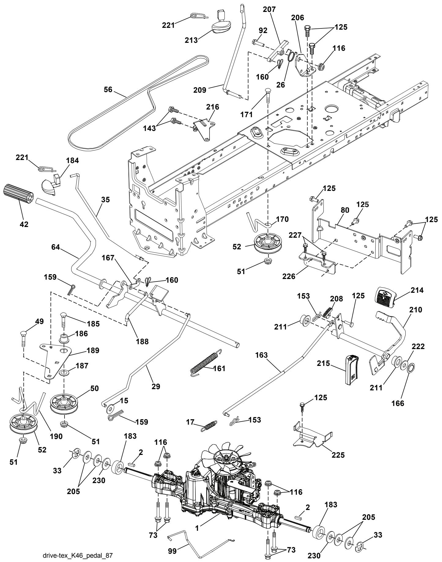
drive-tex_K46_pedal_87
TRACTOR -- MODEL NUMBER 917.240462, PRODUCT NO. YTH20K46 DRIVE
| KEYNO. | PARTNO. | DESCRIPTION |
| 1 | - - - - - - | Transaxle, TUFFTORQ K46BT (426120)(See Transaxle breakdown) |
| 2 | 532 12 35-83 | Key |
| 15 | 819 13 13-16 | Washer 13/32 x 13/16 x 16 Ga. |
| 17 | 532 41 36-78 | Spring, Brake |
| 26 | 532 19 96-79 | Spring Return Cruise |
| 29 | 532 40 38-06 | Rod, Brake |
| 33 | 812 00 00-01 | Ring E |
| 35 | 532 43 54-86 | Rod, Brake, Park |
| 42 | 532 12 48-72 | Cover, Foot Pedal |
| 49 | 872 11 06-14 | Bolt |
| 50 | 532 19 43-27 | Pulley Idler Flat |
| 51 | 873 90 06-00 | Lock Nut 3/8-16 |
| 52 | 532 19 43-26 | Idler V-Groove 910" Offset |
| 56 | 532 13 09-69 | V-Belt, Drive |
| 64 | 532 19 78-65 | Shaft Asm. Pedal Brake Control |
| 73 | 874 49 05-44 | Bolt Hex Flghd 5/16-18 x Gr. 5 |
| 80 | 532 44 06-19 | Bracket Strap Torque |
| 92 | 874 76 05-20 | Bolt Fin Hex 5/16-18 unc x 1.25 |
| 99 | 532 41 57-42 | Rod Spring Bypass |
| 116 | 873 90 05-00 | Nut Lock Hex Flange 5/16-18 |
| 125 | 817 00 05-12 | Screw 5/16-18 x 3/4 |
| 143 | 817 49 05-08 | Screw 5/16-18 x 1/2 |
| 153 | 532 12 47-88 | Retainer Spring |
| 159 | 876 02 04-12 | Pin Cotter 1/8 x 3/4 |
| 160 | 532 16 94-84 | Retainer Clip |
| 161 | 532 10 57-09 | Spring, Return, Clutch |
| 163 | 532 40 10-34 | Rod Pedal Control |
| 166 | 532 42 91-64 | Nut Push |
| 167 | 532 40 52-57 | Latch Brake Parking |
| KEYNO. | PARTNO. | DESCRIPTION |
| 170 | 532 19 43-22 | Keeper Belt Centerspan |
| 171 | 872 11 06-16 | Bolt Rd Hd 3/8-16 x 2 |
| 183 | 532 13 70-57 | Spacer Axle |
| 184 | 532 44 14-55 | Handle Parking Brake |
| 185 | 872 11 06-22 | Bolt Rdhd 3/8-16 unc x 2-3/4 Gr. 5 |
| 186 | 532 19 43-21 | Spacer Retainer |
| 187 | 819 13 32-10 | Washer |
| 188 | 532 19 43-23 | Link Clutch Ground Drive |
| 189 | 532 19 43-17 | Bellcrank Ground Drive |
| 190 | 532 19 43-18 | Keeper Bellcrank Ground Drive |
| 205 | 532 12 17-48 | Washer |
| 206 | 532 19 78-67 | Bracket Mount Latch Cruise |
| 207 | 532 19 78-68 | Latch Control Cruise |
| 208 | 532 19 78-69 | Gear Sector Control Cruise |
| 209 | 532 19 95-92 | Rod Control Cruise |
| 210 | 532 40 09-80 | Rocker Asm. Pedal Control |
| 211 | 532 12 01-83 | Bearing Nylon |
| 213 | 532 40 31-19 | Knob Control Cruise |
| 214 | 532 42 12-63 | Pedal Forward |
| 215 | 532 40 17-23 | Pedal Reverse |
| 216 | 532 19 61-31 | Bracket Pulley Idler |
| 221 | 532 40 31-87 | Retainer Spring Clip Handle |
| 222 | 879 21 20-10 | Washer 21/32 x 1-1/4 10 Ga. |
| 225 | 532 40 33-19 | Keeper Belt Trans. |
| 226 | 532 40 15-64 | Bracket Mount Torque |
| 227 | 817 49 05-12 | Screw Thdrol 5/16-18 x 3/4 |
| 230 | 532 18 89-67 | Washer Hardened |
NOTE: All component dimensions given in U.S. inches 1 inch = 25.4 mm
TRACTOR -- MODEL NUMBER 917.240462, PRODUCT NO. YTH20K46 ENGINE
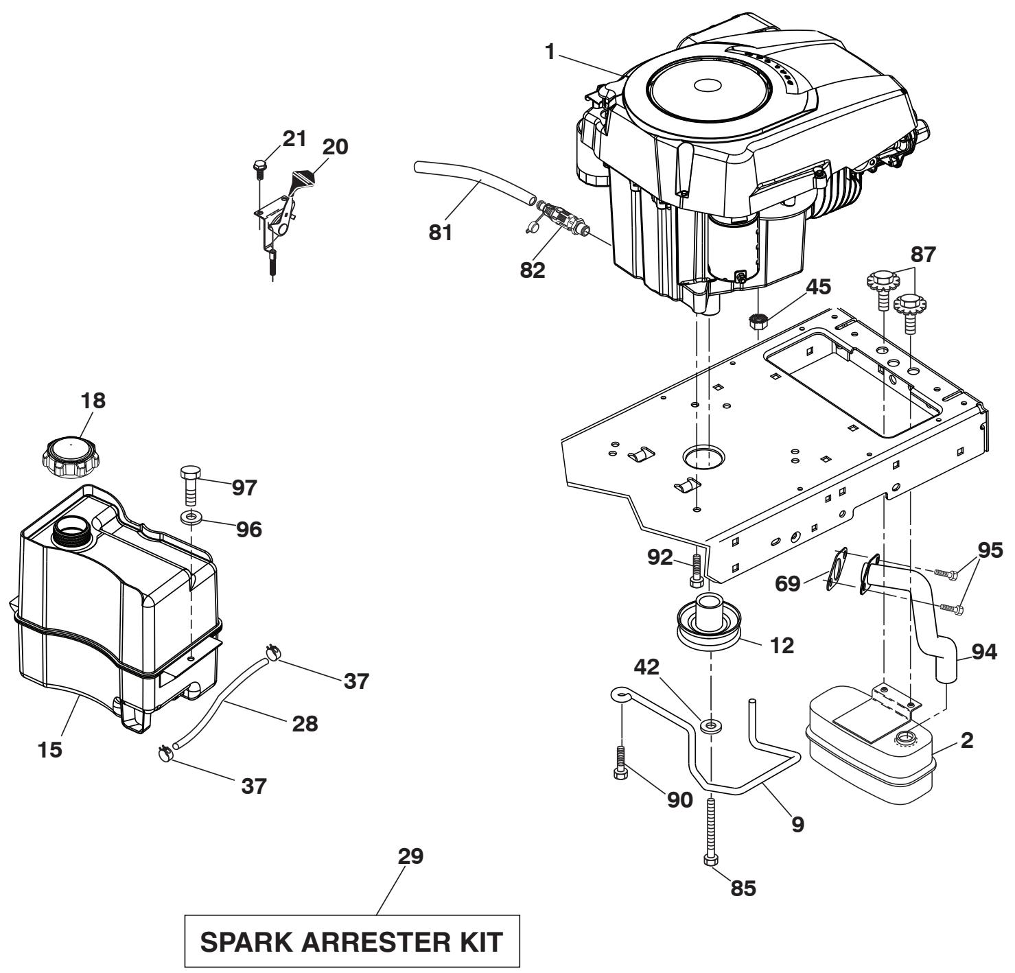
engine-tex_Kohl_29_r1
TRACTOR -- MODEL NUMBER 917.240462, PRODUCT NO. YTH20K46 ENGINE
| KEYNO. | PARTNO. | DESCRIPTION |
| 1 | ---- | Engine Kohler Model No. SV600-0212(422749) (See Engine breakdown) |
| 2 | 532 18 86-55 | Muffler |
| 9 | 532 19 43-20 | Keeper Belt Engine |
| 12 | 532 40 54-72 | Pulley Engine |
| 15 | 532 40 74-89 | Tank Fuel |
| 18 | 532 43 85-96 | Cap Asm |
| 20 | 532 40 15-08 | Control Throttle/Choke |
| 21 | 532 41 63-58 | Screw #10 x 0.750 BOS Thread |
| 28 | 532 40 11-37 | Fuel Line |
| 29 | 532 13 71-80 | Spark Arrester Kit |
| 37 | 532 12 34-87 | Clamp Hose |
| 42 | 810 04 07-00 | Washer Lock 7/16 |
| 45 | 873 51 04-00 | Nut Keps Hex 1/4-20 unc |
| 69 | 532 18 59-09 | Gasket |
| 79 | 532 19 23-34 | Screw Socket Head |
| 81 | 532 14 84-56 | Tube Drain Oil Easy |
| 82 | 532 42 82-87 | Valve Drain Oil |
| 85 | 532 17 39-37 | Bolt Hex 7/16-20 x 4 x Gr. 5-1.5 Thr |
| 87 | 532 17 18-77 | Bolt 5/16-18 unc x 3/4 w/Sems |
| 90 | 817 00 06-16 | Screw 3/8-16 x 1 |
| 92 | 817 12 06-16 | Screw 3/8-16 x 1 |
| 94 | 532 18 86-54 | Tube Exhaust |
| 96 | 819 09 14-16 | Washer 9/32 x 7/8 x 16 Ga. |
| 97 | 817 67 04-12 | Screw Hexwsh Thdrol 1/4-20 x 3/4 |
NOTE: All component dimensions given in U.S. inches 1 inch = 25.4 mm
For engine service and replacement parts, call the toll free number for your engine manufacturer listed below:
Kohler Co. 1-800-544-2444
TRACTOR -- MODEL NUMBER 917.240462, PRODUCT NO. YTH20K46 STEERING ASSEMBLY
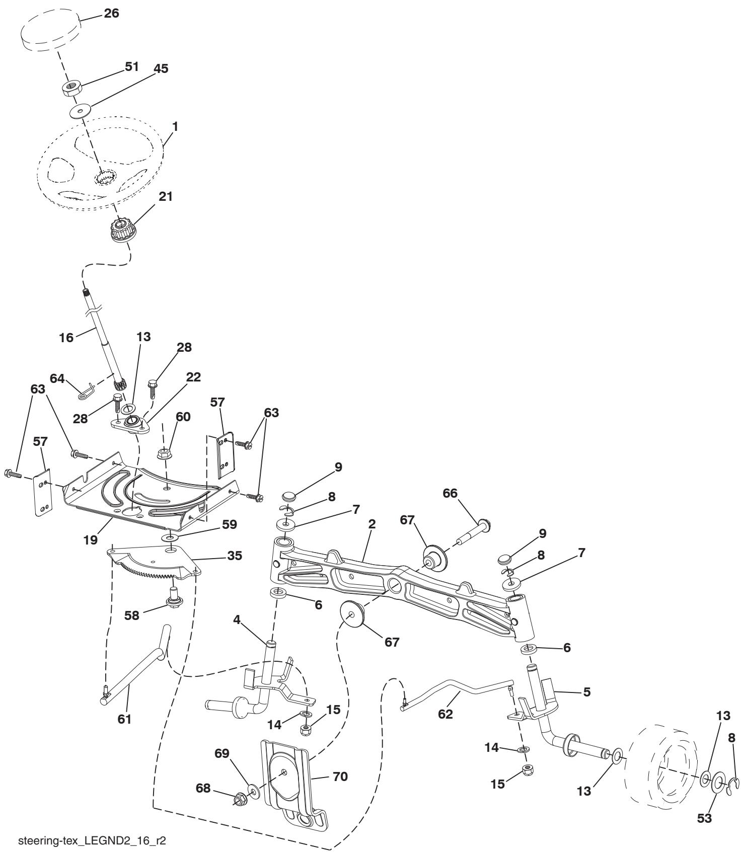
steering-tex_LEGND2_16_r2
TRACTOR -- MODEL NUMBER 917.240462, PRODUCT NO. YTH20K46 STEERING ASSEMBLY
| KEYNO. | PARTNO. | DESCRIPTION |
| 1 | 532 43 97-40 | Wheel, Steering |
| 2 | 532 19 59-68 | Axle Asm., Front |
| 4 | 532 40 30-87 | Spindle Asm., LH |
| 5 | 532 40 30-88 | Spindle Asm., RH |
| 6 | 532 12 49-31 | Bearing, Race Thrust Harden |
| 7 | 532 12 17-48 | Washer 25/32 × 1-5/8 × 16 Ga. |
| 8 | 812 00 00-29 | Ring, Klip #T5304-75 |
| 9 | 532 12 12-32 | Cap, Spindle |
| 13 | 532 12 17-49 | Washer 25/32 × 1-1/4 × 16 Ga. |
| 14 | 810 04 06-00 | Washer, Lock Hvy Hlcl Spr 3/8 |
| 15 | 873 54 06-00 | Nut, Crown Lock 3/8-24 unf |
| 16 | 532 40 82-19 | Shaft Steering |
| 19 | 532 19 47-29 | Plate Steering |
| 21 | 532 18 67-37 | Adapter, Wheel Steering |
| 22 | 532 42 05-37 | Support Strg. Lower |
| 26 | 532 43 97-43 | Insert, Wheel Steering |
| 28 | 817 00 06-12 | Screw 3/8-16 × 3/4 |
| 35 | 532 19 47-32 | Gear, Sector Plate |
| 45 | 819 18 38-12 | Washer 9/16 ID x 2-3/8 OD 12 Ga. |
| 51 | 873 94 08-00 | Nut Hex Jam Toplock 1/2-20 unf |
| 53 | 532 18 89-67 | WasherHardened.793x1.637x.060 |
| 57 | 532 40 74-65 | Bracket Upstop |
| 58 | 532 19 47-47 | Bolt Shoulder Sector Pivot CFM |
| 59 | 532 19 47-48 | Washer Thrust Sector Steering |
| 60 | 873 97 10-00 | Nut Flange Lock 5/8-11 |
| 61 | 532 19 47-40 | Draglink LH |
| 62 | 532 19 47-41 | Draglink, RH |
| 63 | 817 00 05-12 | Screw 5/16-18 × 3/4 |
| 64 | 532 19 98-49 | Retainer Clip Spring Steering |
| 66 | 871 02 07-48 | Bolt Hex Fghd 7/16-14 x 3 Serr |
| 67 | 532 19 47-37 | Bushing PM Front Axle |
| 68 | 873 90 07-00 | Nut Lock Flange 7/16-14 Gr. 5 |
| 69 | 532 19 91-62 | Washer 1.5 × .505 × .118 |
| 70 | 532 19 61-97 | Bracket Deck Susp. Front |
NOTE: All component dimensions given in U.S. inches 1 inch = 25.4 mm
TRACTOR -- MODEL NUMBER 917.240462, PRODUCT NO. YTH20K46 MOWER DECK
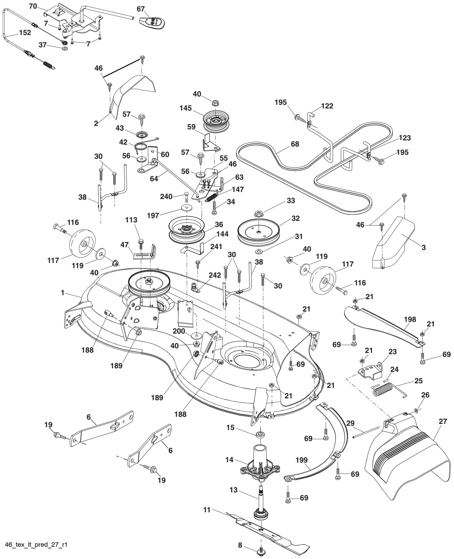
46_tex_lt_pred_27_r1
TRACTOR -- MODEL NUMBER 917.240462, PRODUCT NO. YTH20K46 MOWER DECK
| KEYNO. | PARTNO. | DESCRIPTION | KEYNO. | PARTNO. | DESCRIPTION |
| 1 | 532 44 23-82 | Mower Housing | 60 | 532 19 94-71 | Arm Brake Mower LH |
| 2 | 532 40 55-07 | Cover Mandrel LH | 63 | 532 19 94-77 | Arm Brake Mower |
| 3 | 532 40 55-06 | Cover Mandrel RH | 64 | 532 40 51-38 | Linkage Brake |
| 6 | 532 19 51-86 | Arm Suspension | 67 | 532 40 30-12 | Handle, Clutch Cable |
| 7 | 532 41 63-58 | Screw #10 x 0.750 BOS Thread | 68 | 532 40 51-43 | V-Belt |
| 8 | 532 19 30-03 | Bolt/Washer asm 7/16-20 unf | 69 | 872 14 05-05 | Bolt |
| 11 | 532 40 53-80 | Blade Mower | 70 | 532 19 99-72 | Clutch Asm. |
| -- | 532 40 31-07 | Blade, 46" Mulching | 113 | 817 00 05-10 | Screw 5/16-18 |
| 13 | 532 19 28-72 | Shaft Assembly, Mandrel | 116 | 532 19 34-06 | Bolt, Shoulder |
| 14 | 532 18 72-81 | Housing, Mandrel | 117 | 532 17 48-73 | Wheel, Gauge |
| 15 | 532 11 04-85 | Bearing, Ball, Mandrel | 119 | 819 13 20-12 | Washer 13/32 x 1-1/4 x 12 Ga. |
| 19 | 532 19 65-39 | Bolt, Shoulder | 122 | 532 19 72-58 | Keeper Belt Eng. LH |
| 21 | 873 68 05-00 | Nut | 123 | 532 19 72-59 | Keeper Belt Eng. RH |
| 23 | 532 19 25-57 | Bracket, Deflector | 144 | 532 19 92-04 | Keeper Belt |
| 24 | 532 10 53-04 | Cap, Sleeve | 145 | 532 19 31-97 | Pulley Idler |
| 25 | 532 19 70-26 | Spring, Torsion, Deflector | 147 | 532 40 18-72 | Spring Return |
| 26 | 532 11 04-52 | Nut, Push | 152 | 532 43 51-10 | Cable Clutch Cbl. w/Spr. |
| 27 | 532 40 53-57 | Shield, Deflector | 188 | 532 19 51-61 | Stud Fastener |
| 29 | 532 13 14-91 | Rod, Hinge | 189 | 873 90 05-00 | Nut Lock Hex Flange |
| 30 | 532 17 39-84 | Screw Thdrol Rolling Wsh Hd | 195 | 817 00 06-12 | Screw 3/8-16 x 3/4 |
| 31 | 532 18 76-90 | Washer, Spacer | 197 | 819 13 13-12 | Washer 13/32 x 13/16 x 12 Ga. |
| 32 | 532 19 74-73 | Pulley, Mandrel | 198 | 532 40 31-49 | Baffle Center Front |
| 33 | 532 40 02-34 | Nut, Toplock, Flanged | 199 | 532 40 31-50 | Baffle Front RH |
| 34 | 872 11 06-12 | Bolt Carr Sh. 3/8-16 x 1-1/2 Gr. 5 | 200 | 532 41 35-24 | Washer 13/32 x 1 x 1/2 Ga. |
| 36 | 532 19 73-79 | Pulley, Idler, 4.50 RAW | 240 | 874 52 06-36 | Bolt 3/8-16 unc x 2-1/4 Gr. 5 |
| 37 | 819 13 13-16 | Washer 13/32 x 13/16 x 16 Ga. | 241 | 532 15 29-27 | Screw TT #10-32.5 3/8 Flg. |
| 38 | 532 43 25-20 | Keeper Belt Mandrel | 242 | 532 41 55-98 | Port Washout |
| 40 | 873 90 06-00 | Nut, Lock Flg. 3/8-16 unc | -- | 532 41 64-05 | Coupling Quick Connect |
| 42 | 532 19 84-10 | Spring Trosion Brake | -- | 532 19 28-70 | MandrelAssembly (Includes housing, shaft assembly, and bearing only - pulley/nut/washer and blade bolt/washers not included) |
| 43 | 532 19 72-56 | Spring Torsion Retainer | |||
| 46 | 532 13 77-29 | Screw | |||
| 47 | 532 19 72-50 | Bracket Clutch Cable | |||
| 55 | 532 19 72-49 | Arm, Idler | -- | 532 43 18-23 | Replacement Mower, Complete |
| 56 | 532 19 90-92 | Spacer, Retainer | |||
| 57 | 817 00 06-16 | Screw Hexwsh Thd 3/8-16 x 1 | NOTE: All component dimensions given in U.S. inches | ||
| 59 | 532 14 10-43 | Guard, Tuv Idler (94) | 1 inch = 25.4 mm | ||
| KEYNO. | PARTNO. | DESCRIPTION |
| 60 | 532 19 94-71 | Arm Brake Mower LH |
| 63 | 532 19 94-77 | Arm Brake Mower |
| 64 | 532 40 51-38 | Linkage Brake |
| 67 | 532 40 30-12 | Handle, Clutch Cable |
| 68 | 532 40 51-43 | V-Belt |
| 69 | 872 14 05-05 | Bolt |
| 70 | 532 19 99-72 | Clutch Asm. |
| 113 | 817 00 05-10 | Screw 5/16-18 |
| 116 | 532 19 34-06 | Bolt, Shoulder |
| 117 | 532 17 48-73 | Wheel, Gauge |
| 119 | 819 13 20-12 | Washer 13/32 x 1-1/4 x 12 Ga. |
| 122 | 532 19 72-58 | Keeper Belt Eng. LH |
| 123 | 532 19 72-59 | Keeper Belt Eng. RH |
| 144 | 532 19 92-04 | Keeper Belt |
| 145 | 532 19 31-97 | Pulley Idler |
| 147 | 532 40 18-72 | Spring Return |
| 152 | 532 43 51-10 | Cable Clutch Cbl. w/Spr. |
| 188 | 532 19 51-61 | Stud Fastener |
| 189 | 873 90 05-00 | Nut Lock Hex Flange |
| 195 | 817 00 06-12 | Screw 3/8-16 x 3/4 |
| 197 | 819 13 13-12 | Washer 13/32 x 13/16 x 12 Ga. |
| 198 | 532 40 31-49 | Baffle Center Front |
| 199 | 532 40 31-50 | Baffle Front RH |
| 200 | 532 41 35-24 | Washer 13/32 x 1 x 1/2 Ga. |
| 240 | 874 52 06-36 | Bolt 3/8-16 unc x 2-1/4 Gr. 5 |
| 241 | 532 15 29-27 | Screw TT #10-32.5 3/8 Flg. |
| 242 | 532 41 55-98 | Port Washout |
| -- | 532 41 64-05 | Coupling Quick Connect |
| -- | 532 19 28-70 | MandrelAssembly (Includes housing, shaft assembly, and bearing only - pulley/nut/washer and blade bolt/washers not included) |
| -- | 532 43 18-23 | Replacement Mower, Complete |
NOTE: All component dimensions given in U.S. inches 1 inch = 25.4 mm
TRACTOR -- MODEL NUMBER 917.240462, PRODUCT NO. YTH20K46 MOWER LIFT
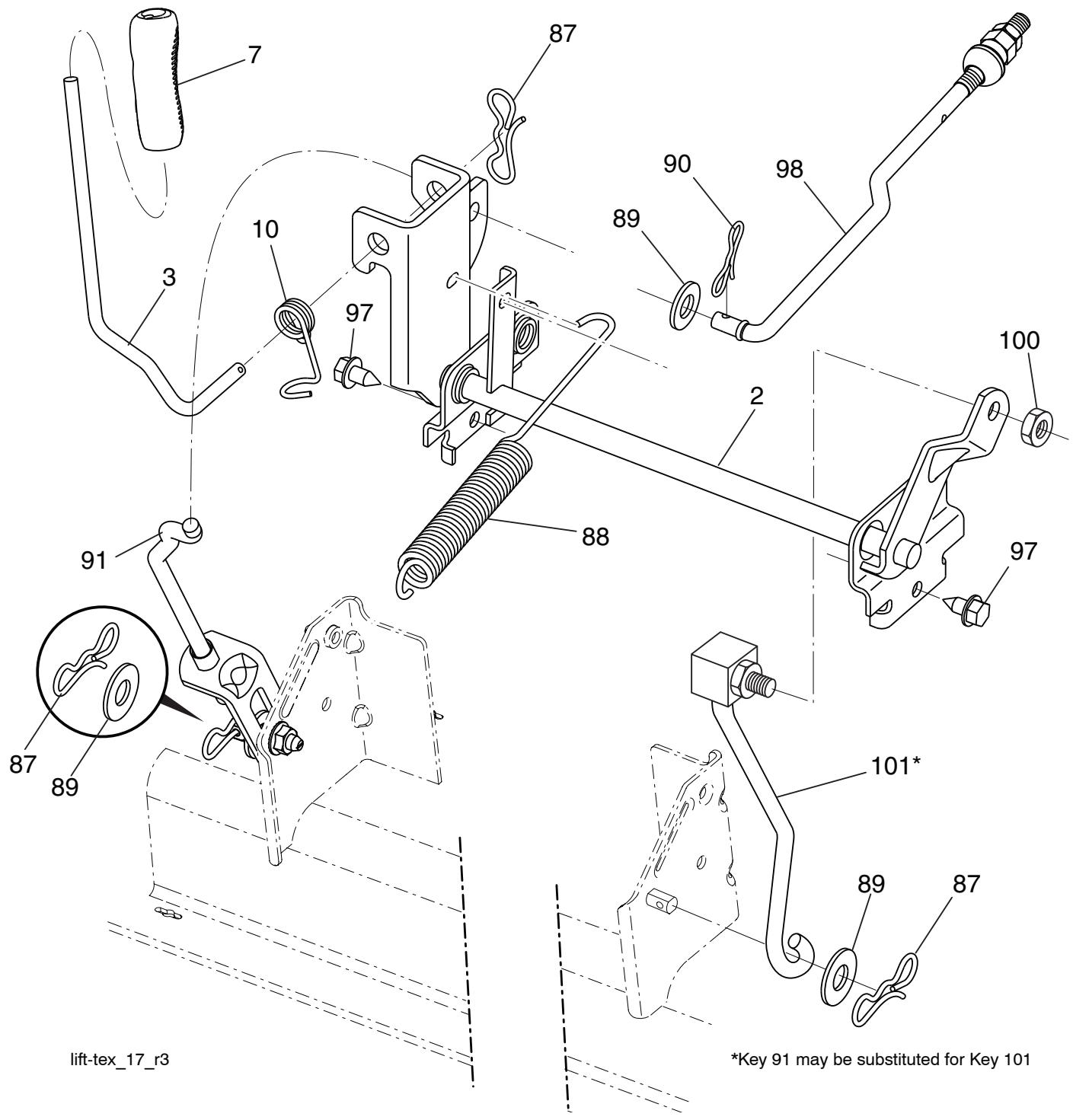
KEY PART
NO. NO.
| 2 | 532 42 20-27 | Shaft Asm., Lift |
| 3 | 532 19 52-31 | Lever Asm., Lift RH |
| 7 | 532 41 15-55 | Grip, Lever |
| 10 | 532 19 63-14 | Spring Torsion |
| 87 | 532 19 42-09 | Pin Cotter 7/16 Bow Tie Lock |
| 88 | 532 41 07-10 | Spring Lift Assist |
| 89 | 819 19 19-12 | Washer Clear Zinc |
| 90 | 532 19 42-08 | Pin Cotter 5/16 Bow Tie Lock |
KEY PART
NO. NO.
| 91 | 532 19 51-81 | Link Lift Susp Mower Rear |
| 97 | 817 00 06-12 | Screw 3/8-16 x .75 |
| 98 | 532 19 52-70 | Link Lift Susp. Front Mower |
| 100 | 873 93 06-00 | Nut Center Lock 3/8-16 unc |
| 101 | 532 40 70-03 | Link Asm. Lift FXD |
NOTE: All component dimensions given in U.S. inches 1 inch = 25.4 mm
TRACTOR -- MODEL NUMBER 917.240462, PRODUCT NO. YTH20K46 SEAT ASSEMBLY
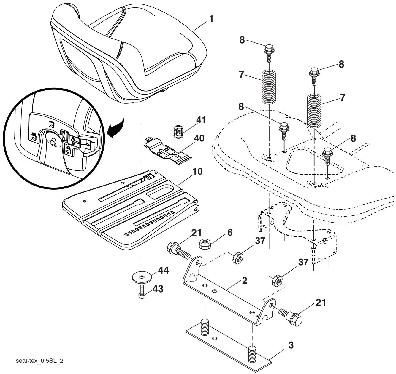
KEY PART
NO. NO.
| 1 | 532 | 43 | 98-22 |
| 2 | 532 | 18 | 01-66 |
| 3 | 532 | 14 | 06-75 |
| 6 | 873 | 80 | 06-00 |
| 7 | 532 | 12 | 41-81 |
| 8 | 532 | 17 | 18-77 |
| 10 | 532 | 19 | 69-77 |
| 21 | 532 | 17 | 18-52 |
DESCRIPTION
| Seat |
| Bracket Pivot Fender |
| Strap, Asm Fender |
| Nut, Lock w/Ins. 3/8-16 unc |
| Spring, Seat Cprsn |
| Bolt 5/16-18 unc x 3/4 w/Sems |
| Pan, Seat |
| Bolt, Shoulder 5/16-18 |
KEY PART
NO. NO. DESCRIPTION
| 37 | 873 80 05-00 | Nut, Lock 5/16-18 unc |
| 40 | 532 19 76-61 | Handle Slide Seat |
| 41 | 532 19 82-00 | Spring Latch Seat |
| 43 | 874 76 06-12 | Bolt Fin Hex 3/8-16 unc x 3/4 |
| 44 | 819 13 38-12 | Washer 13/32 x 2-3/8 x 12 Ga. |
NOTE: All component dimensions given in U.S. inches 1 inch = 25.4 mm
TRACTOR -- MODEL NUMBER 917.240462, PRODUCT NO. YTH20K46 DECALS
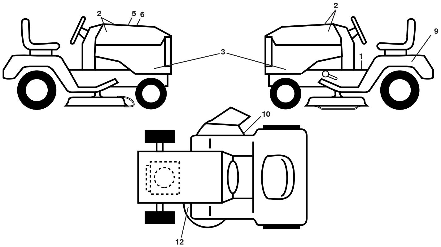
KEY PART
NO. NO.
| 1 | 532 41 16-57 |
| 2 | 532 42 91-96 |
| 5 | 532 42 38-29 |
| 6 | 532 44 14-53 |
| 9 | 532 14 50-05 |
| 10 | 532 17 05-63 |
DESCRIPTION
| Decal, Operators |
| Decal, Badge |
| Decal, Customer Respons. |
| Decal, Replacement |
| Decal, Battery Dnge/Poi |
| Decal, Warning |
KEY PART
NO. NO.
| 12 | 532 16 03-96 |
| -- | 532 16 69-60 |
| -- | 532 43 96-81 |
| -- | 532 43 96-82 |
| -- | 532 44 41-49 |
| -- | 532 44 41-50 |
DESCRIPTION
| Decal, Mower V-Belt Schematic |
| Decal, Bypass |
| Pad, Footrest, LH |
| Pad, Footrest, RH |
| Manual, Owner's (English) |
| Manual, Owner's (Spanish) |
WHEELS AND TIRES
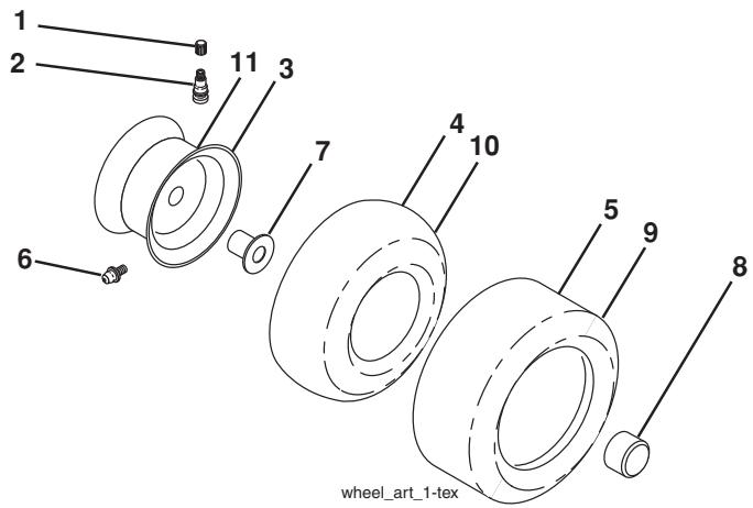
KEY PART
NO. NO.
| 1 | 532 05 91-92 |
| 2 | 532 06 51-39 |
| 3 | 532 13 83-36 |
| 4 | 532 05 99-04 |
| 5 | 532 10 62-22 |
| 6 | 532 12 49-57 |
| 7 | 532 12 49-59 |
| 8 | 532 17 50-39 |
| 9 | 532 13 84-68 |
| 10 | 532 12 49-26 |
| 11 | 532 13 83-37 |
| -- | 532 14 43-34 |
DESCRIPTION
| Cap Valve Tire |
| Stem Valve |
| Rim Front Service |
| Tube Front (Service Item Only) |
| Tire Front 15 x 6.0-6 Service |
| Fitting Grease (Front Wheel Only) |
| Bearing Flange (Front Wheel Only) |
| Cap Axle Blk 1 50 x 1 00 |
| Tire R Ts 20 x 8-8 |
| Tube Rear (Service Item Only) |
| Rim Asm 8" rear Service |
| Sealant, Tire (10 oz. Tube) |
NOTE: All component dimensions given in U.S. inches 1 inch = 25.4 mm
TRACTOR -- MODEL NUMBER 917.240462, PRODUCT NO. YTH20K46 TUFFTORQ TRANSAXLE MODEL NUMBER K46BT
MODEL K46BT 7A646084180
ACTUAL PARTS MAY NOT APPEAR AS SHOWN
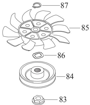
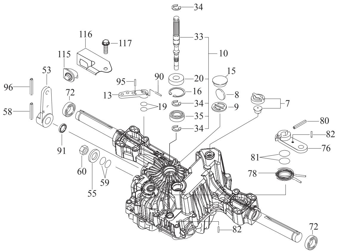
KEY PART NO. NO.
| 7 | 414395 |
| 8 | 414396 |
| 9 | 414397 |
| 10 | 415923 |
| 13 | 414398 |
| 15 | 414399 |
| 16 | 414400 |
| 19 | 414401 |
| 20 | 414402 |
| 33 | 414403 |
| 34 | 414404 |
| 35 | 414405 |
| 53 | 414431 |
| 55 | 415924 |
| 58 | 415925 |
| 59 | 415926 |
| 60 | 415927 |
| 72 | 414407 |
| 76 | 414408 |
DESCRIPTION
| Vent Valve 15 |
| Magnet |
| Magnet Holder |
| Pump Shaft/Bearing Kit |
| Bypass Lever |
| Sealing Cap 30 |
| Snap Ring C 35 |
| O-Ring 1a P10a |
| Seal Tc 153507 |
| Pump Shaft (Standard) |
| E-Ring 15 |
| Bearing 6202c3 |
| Control Lever F |
| Washer 12 |
| Roll Pin 6 * 40 |
| O-Ring 1a P14 |
| Nut 12 |
| Seal 19 * 32 * 8 |
| Brake Lever |
KEY PART NO. NO.
| 78 | 414409 | Brake Return Spring |
| 80 | 414410 | Spring Pin 5 * 32 |
| 81 | 414411 | 0-Ring 1a P12 |
| 82 | 414412 | Spring Pin 4 * 16 |
| 83 | 414413 | Spine Collar |
| 84 | 414414 | Pulley L |
| 85 | 414415 | Fan, Black |
| 86 | 414416 | Wave Washer |
| 87 | 414417 | Snap Ring |
| 90 | 414418 | Spring Pin 3.0a * 20 |
| 91 | 414419 | Oil Seal 16 * 22 *.03 |
| 95 | 414850 | Spring Pin 3.0a*16 |
| 96 | 414420 | Roll Pin 3.5 * 40 |
| 115 | 415928 | Switch 6440-11 Delta |
| 116 | 415929 | Switch Bracket |
| 117 | 415930 | Tapping Screw 8 * 20 |
NOTE: All component dimensions given in U.S. inches 1 inch = 25.4 mm
CRANKSHAFT 1-20-4
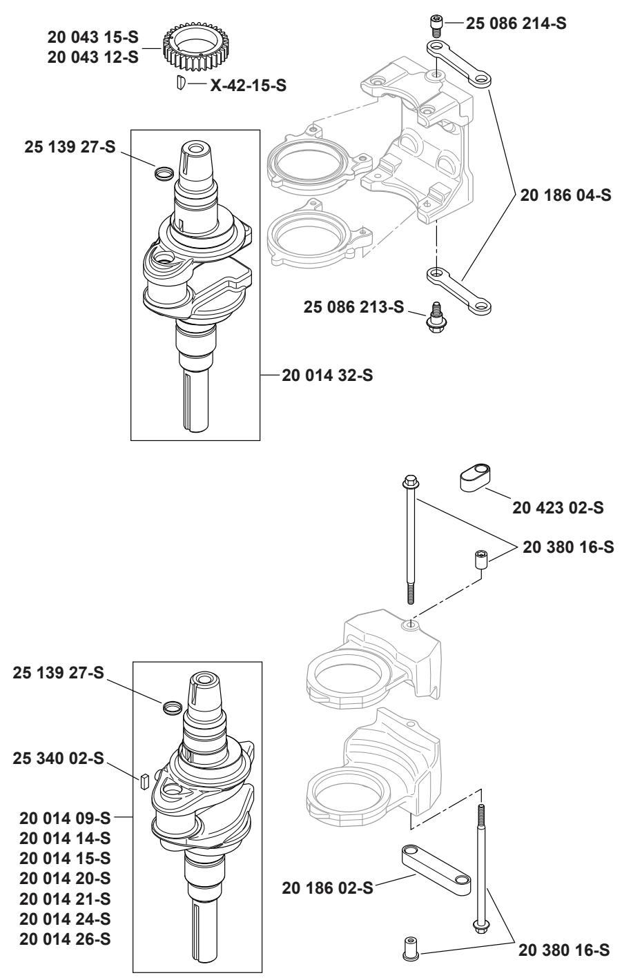
CRANKCASE 2-20-22
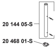
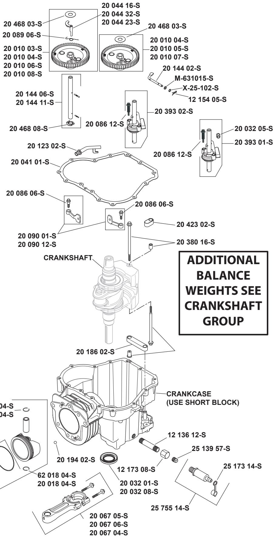
OIL PAN/LUBRICATION 3-20-40
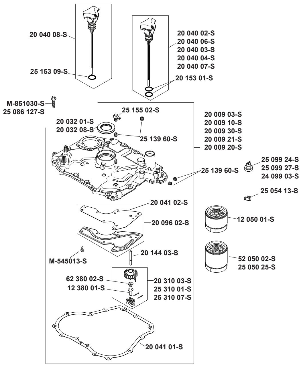
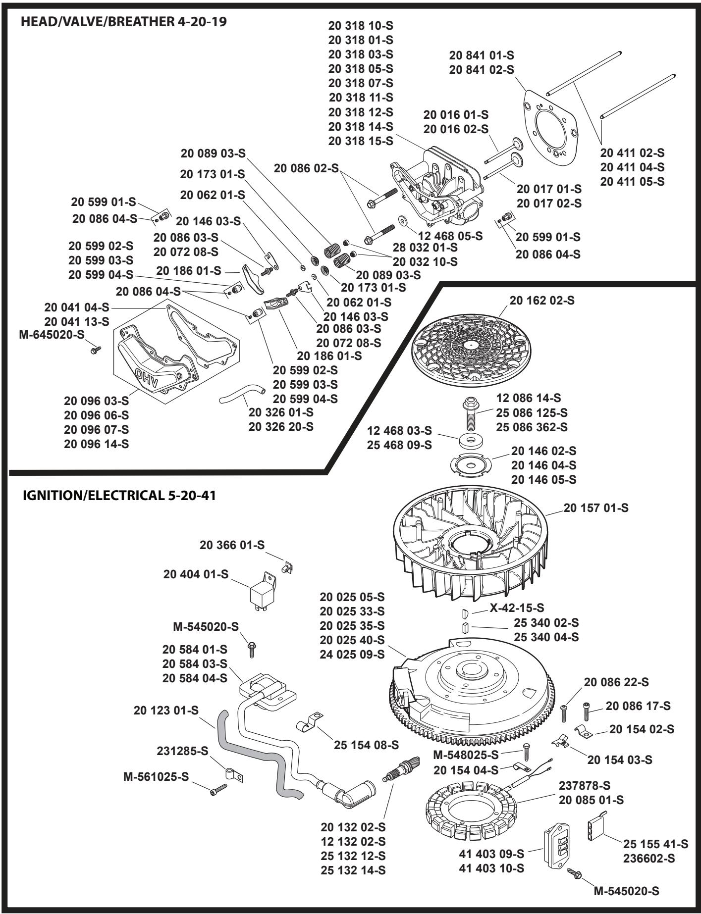
BLOWER HOUSING & BAFFLES 6-20-7
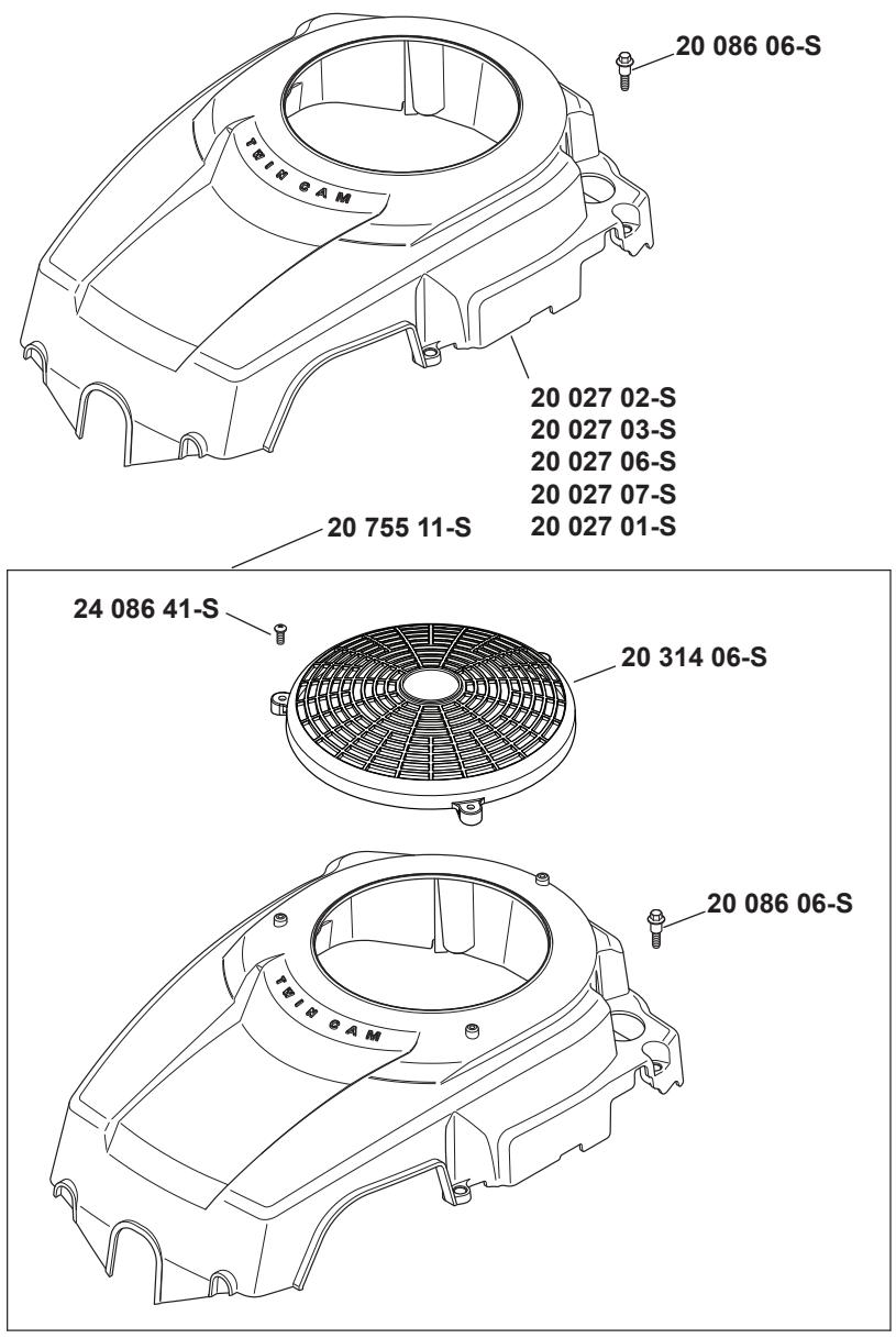

STARTING SYSTEM 7-20-1
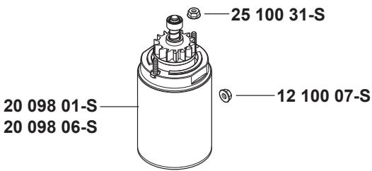
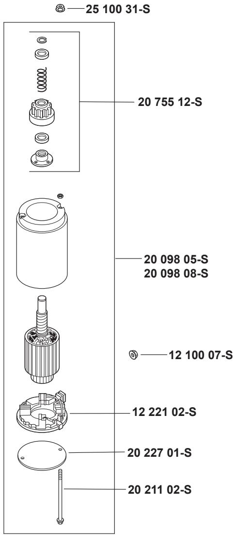
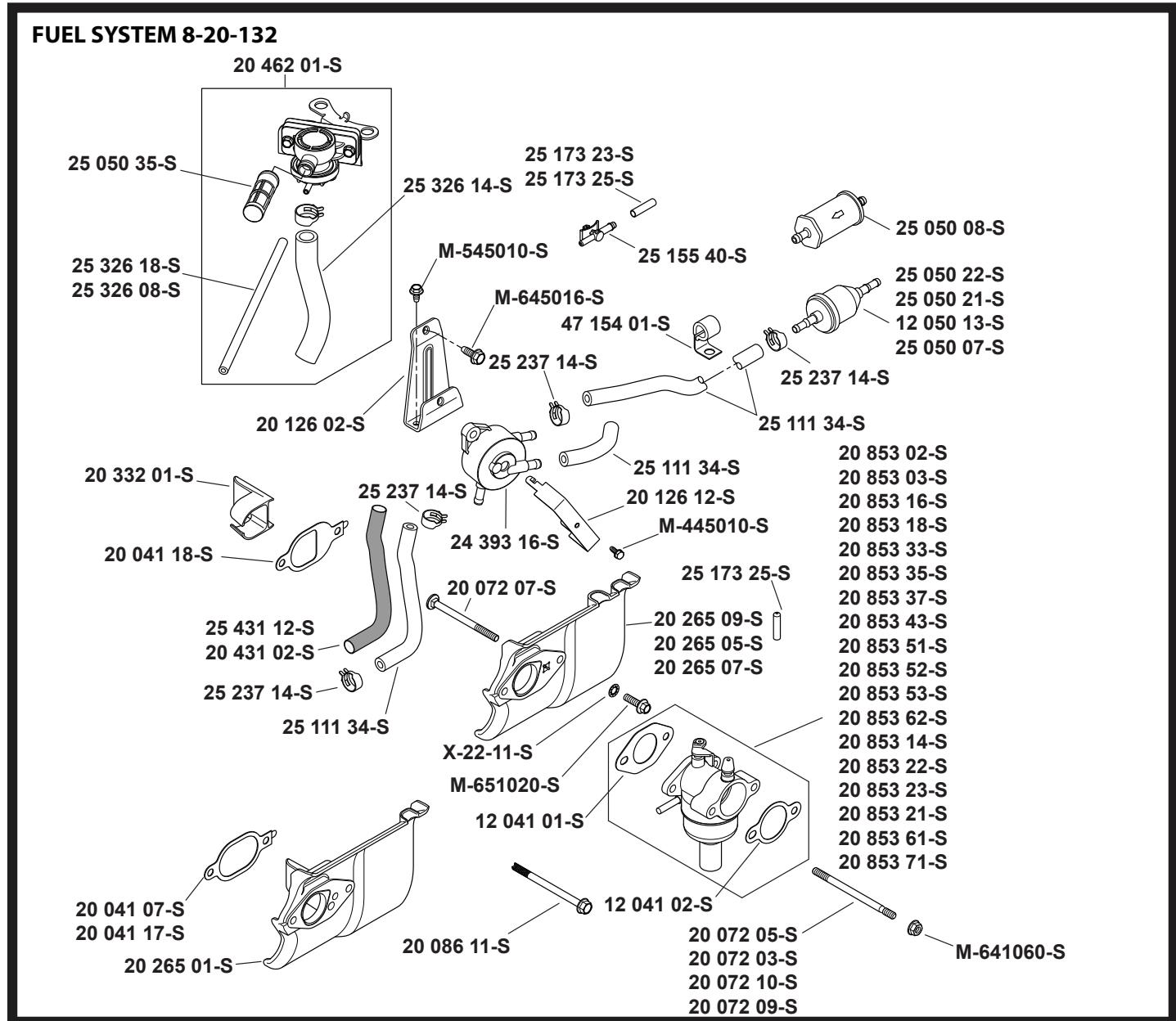
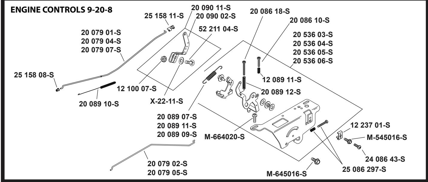
TRACTOR - - MODEL NUMBER 917.240462, PRODUCT NO. YTH20K46 KOHL ENGINE - MODEL NO. SV600-0212
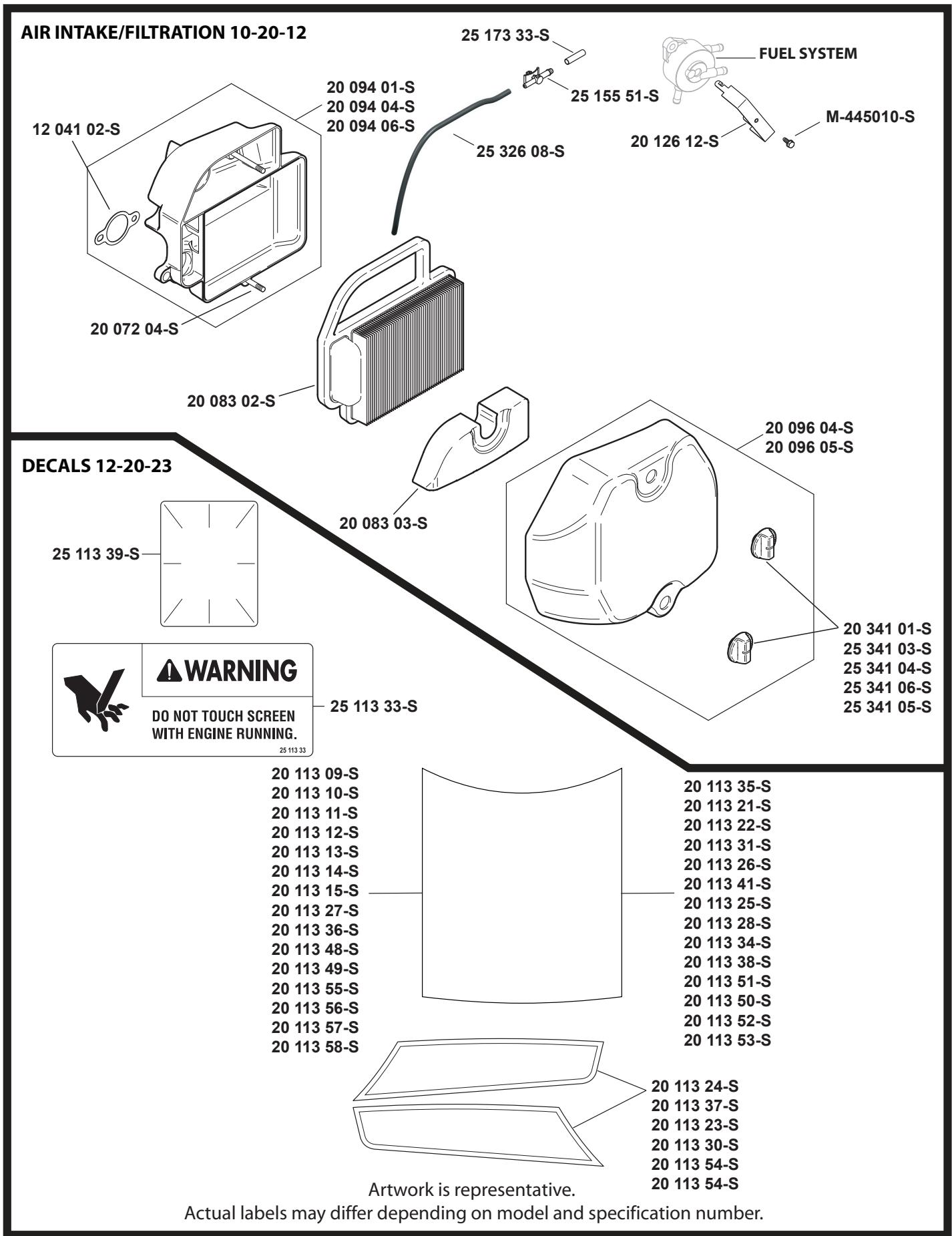
TRACTOR - - MODEL NUMBER 917.240462, PRODUCT NO. YTH20K46 KOHL ENGINE - MODEL NO. SV600-0212
CRANKSHAFT 1-20-4
| PART NO. | QTY. | DESCRIPTION |
| 20 014 32-S | 1 | Kit, Crankshaft Assembly(Includes 25 139 27-S) |
| 25 139 27-S | 1 | Plug, Cup |
| X-42-15-S | 1 | Key, 3/16" X 5/8" |
| 20 043 15-S | 1 | Gear, Crankshaft |
| 25 086 137-S | 4 | Screw, Flg M6x1.0x25 |
| 25 086 214-S | 1 | Screw, Link Pivot |
| 20 186 04-S | 2 | Linkage, Balance Weight |
| 25 086 213-S | 1 | Screw, Shoulder |
CRANKCASE 2-20-16
| PART NO. | QTY. | DESCRIPTION |
| 1 | Crankcase (Use Short Block) | |
| 20 032 01-S | 1 | Seal, Oil |
| 20 067 05-S | 1 | Rod, Connecting Assembly |
| 20 874 09-S | 1 | Kit, Piston W/Ring Set (94Mm)(Includes 20 108 04-S, 62 018 04-S) |
| 20 108 04-S | 1 | Ring Set (94Mm) |
| 62 018 04-S | 2 | Retainer, Piston Pin |
| 20 090 01-S | 2 | Kit, Cam Lever Assembly(Includes 20 086 06-S) |
| 20 086 06-S | 2 | Screw, Shd Thd Frm M6x1x26 |
| 20 041 01-S | 1 | Gasket, Closure Plate |
| 20 123 02-S | 1 | Tube, Drainback |
| 12 154 05-S | 1 | Clip, Hitch Pin |
| M-631015-S | 1 | Washer, Flat 6 Mm |
| X-25-102-S | 1 | Washer, Flat 1/4" |
| 20 144 02-S | 1 | Shaft, Governor Cross |
| 20 393 02-S | 1 | Kit, Oil Pump Assembly (Includes20 041 01-S, 20 112 02-S, 20 086 13-S) |
| 20 112 02-S | 2 | Spacer, Oil Pump Screw |
| 20 086 13-S | 2 | Screw, Oil Pump |
| 20 144 11-S | 1 | Kit,Cam Center Shaft (Exhaust)(Includes 20 468 08-S) |
| 20 468 08-S | 1 | Washer, Thrust |
| 20 010 04-S | 1 | Kit, Camshaft Assembly (Includes20 089 06-S, 20 044 23-S, 20 468 03-S) |
| 20 089 06-S | 1 | Spring, Acr |
| 20 468 03-S | 1 | Washer, Thrust -Acr |
| 20 010 04-S | 1 | Kit, Camshaft Assembly(Includes 20 468 03-S) |
| 20 468 03-S | 1 | Washer, Thrust -Acr |
| 25 139 57-S | 1 | Plug, Sq Hd Pipe 3/8" |
| 20 044 16-S | 1 | Use 20 044 23-S Acr Weight |
OIL PAN/LUBRICATION 3-20-28
| PART NO. | QTY. | DESCRIPTION |
| 20 040 06-S | 1 | Dipstick Assembly-Std Yellow(Includes 20 153 01-S) |
| 20 153 01-S | 2 | O-Ring |
| 20 009 30-S | 1 | Closure Plate Assembly(Includes 25 139 60-S, 20 096 02-S, 20 041 02-S, 20 144 03-S, 25 310 07-S, 12 380 01-S, 20 041 01-S, M-545013-S, 20 032 01-S, 25 155 02-S) |
| 25 139 60-S | 4 | Plug, Ctsk Pipe 1/8" |
| 20 096 02-S | 1 | Kit, Oil Passage Cover(Includes 20 041 02-S) |
| 20 041 02-S | 1 | Gasket, Oil Passage |
| 20 144 03-S | 1 | Shaft, Governor Cross |
| 25 310 07-S | 1 | Governor Gear Assembly(Includes 12 380 01-S, 62 380 02-S) |
| 12 380 01-S | 1 | Pin, Governor Regulating |
| 20 041 01-S | 1 | Gasket, Closure Plate |
| M-545013-S | 6 | Screw, Flg Thd Frm M5x0.8x13 |
| 20 032 01-S | 1 | Seal, Oil |
| 25 155 02-S | 1 | Connector, 90° Hose |
| 25 086 127-S | 14 | Hex Flange Screw,1/2 Dog Point |
| 52 050 02-S | 1 | Filter, Oil |
HEAD/VALVE/BREATHER 4-20-1
| PART NO. | QTY. | DESCRIPTION |
| 20 096 07-S | 1 | Kit, Valve Cover(Includes 20 041 13-S) |
| 20 041 13-S | 1 | Gasket, Valve Cover |
| M-645020-S | 7 | Screw, Flg Thd Frm M6x1.0x20 |
| 20 326 20-S | 1 | Hose, Breather |
| 20 599 04-S | 2 | Rocker Pivot Assembly(Includes 20 086 04-S) |
| 20 086 04-S | 2 | Screw, Set |
| 20 186 01-S | 2 | Arm, Rocker |
| 20 072 08-S | 2 | Stud, Rocker |
| 20 146 03-S | 2 | Plate, Push Rod Guide |
| 20 062 01-S | 2 | Lock, Retainer |
| 20 173 01-S | 2 | Cap, Valve Spring |
| 20 089 03-S | 2 | Spring, Valve |
| 12 468 05-S | 1 | Washer, Flat 13/32" |
| 20 086 02-S | 6 | Screw, Flg M10x1.5x80 |
| 20 016 01-S | 1 | Valve, Exhaust |
| 20 017 01-S | 1 | Valve, Exhaust |
| 20 841 01-S | 1 | "Kit, Cylinder Head Gasket(Includes 12 041 01-S, 12 041 02-S,12 468 05-S, 20 041 12-S, 20 041 13-S,20 041 17-S, 20 041 18-S, 20 086 02-S,25 086 87-S & X-21-1-S)" |
| 20 411 04-S | 2 | Rod, Push |
| 20 318 11-S | 1 | Kit, Cylinder Head(Includes 25 086 87-S & X-21-1-S) |
| 20 599 03-S | 2 | Kit Pivot, Rocker Arm(Includes 20 086 04-S) |
NOT ILLUSTRATED
| 12 041 01-S | 1 | Gasket, Carburetor |
| 12 041 02-S | 1 | Gasket, Air Cleaner Base |
| 20 041 12-S | 1 | Gasket, Exhaust |
| 20 041 18-S | 1 | Gasket, Heat Deflector |
| 20 041 17-S | 1 | Gasket, Heat Deflector |
| 25 086 87-S | 2 | Screw, Hex Socket Head Cap |
| X-21-1-S | 2 | Washer, Spring Lock 5/16" |
IGNITION/ELECTRICAL 5-20-1
| PART NO. | QTY. | DESCRIPTION |
| 20 162 02-S | 1 | Screen, Grass |
| 25 086 125-S | 1 | Screw, Hex Flange |
| 25 468 09-S | 1 | Washer, Flat |
| 20 146 05-S | 1 | Plate, Fan Mounting |
| 20 157 01-S | 1 | Fan |
| 25 340 02-S | 1 | Key, Straight Flywheel |
| 20 025 40-S | 1 | Flywheel |
| M-548025-S | 2 | Screw, Thd Frm M5x0.8x25 |
| 20 154 04-S | 1 | Clip, Wire |
| 237878-S | 1 | Kit, 15 Amp Stator(Includes 25 452 01-S) |
| 25 155 41-S | 1 | Connector |
| M-545020-S | 2 | Screw, Flg Thd Frm M5x.8X20 |
| 41 403 10-S | 1 | Regulator/Rectifier |
| 20 584 03-S | 1 | Module, Ignition (Cdi Fixed) |
| M-545020-S | 2 | Screw, Flg Thd Frm M5x.8X20 |
| 12 132 02-S | 1 | Plug, Spark (Std) |
TRACTOR - - MODEL NUMBER 917.240462, PRODUCT NO. YTH20K46 KOHL ENGINE - MODEL NO. SV600-0212
NOT ILLUSTRATED
| 20 176 13-S | 1 | Harness, Wiring |
| 25 452 01-S | 2 | Terminal |
| 25 454 05-S | 1 | Tie |
BLOWER HOUSING & BAFFLES 6-20-5
PART NO. QTY. DESCRIPTION
| 20 027 07-S | 1 | Kit, Blower Housing(Includes 41 037 10-S) |
| 20 086 06-S | 4 | Screw, Shd Thd Frm M6x1x26 |
NOT ILLUSTRATED
| 41 037 10-S | 1 | Nameplate, Service |
STARTING SYSTEM 7-20-1
PART NO. QTY. DESCRIPTION
| 20 098 05-S | 1 | Starter Assembly (Service With 12 221 02-S, 20 755 12-S, 20 227 01-S, 20 211 02-S) |
| 25 100 31-S | 2 | Nut, Free Spinning Flg #10-24 |
| 12 221 02-S | 1 | Brush Kit |
| 20 755 12-S | 1 | Kit, Drive (J.E.) |
| 20 227 01-S | 1 | Cap, Drive End (J.E.) |
| 20 211 02-S | 1 | Bolt, Thru |
FUEL GROUP 8-20-40
PART NO. QTY. DESCRIPTION
| 25 237 14-S | 4 | Clamp, Hose 1/2" |
| 25 111 34-S | 2 | Line, Fuel (24"-Cut To Length) |
| 20 265 09-S | 1 | Kit, Heat Deflector (Includes 12 041 02-S, 20 041 18-S, 20 072 07-S, 20 332 01-S) |
| X-22-11-S | 1 | Washer, Int Tooth Lock 1/4" |
| M-651020-S | 1 | Screw, Flg M6x1.0x20 |
| 20 853 35-S | 1 | Kit, Carburetor (Includes 12 041 01-S,12 041 02-S) (S/W 12 755 109-S, 12 755 110-S, 12 757 02-S, 12 757 03-S, 12 757 33-S, 12 757 37-S, 20 755 07-S) |
| 12 041 01-S | 1 | Gasket, Carburetor |
| 12 041 02-S | 1 | Gasket, Air Cleaner Base |
| 20 072 05-S | 1 | Stud, M6x1.0x100 |
| M-641060-S | 2 | Nut, Flg M6x1.0 |
| 20 072 07-S | 1 | Stud, Carburetor |
| 20 041 18-S | 1 | Gasket, Heat Deflector |
| 20 332 01-S | 1 | Insert, Intake Port |
| 25 050 21-S | 1 | Filter, Fuel |
NOT ILLUSTRATED
| 25 454 05-S | 1 | Tie |
| 12 755 109-S | 1 | Kit,High Alt(5000 Or 10000 Ft) |
| 12 755 110-S | 1 | Kit, Repair Choke |
| 12 757 02-S | 1 | Kit, Repair Float |
| 12 757 03-S | 1 | Kit, Repair Carburetor |
| 12 757 33-S | 1 | Kit, Repair Solenoid |
| 12 757 37-S | 1 | Kit, Repair Bowl Replacement |
| 20 755 07-S | 1 | Kit, High Altitude (10,000 Ft) |
ENGINE CONTROLS 9-20-8
PART NO. QTY. DESCRIPTION
| 20 536 06-S | 1 | Kit, Speed Control Assembly(Includes 25 086 297-S, 20 089 12-S,M-66420-S [Qty.1], 20 089 11-S, 20 08618-S, 20 086 10-S , 12 089 11-S) |
| 25 086 297-S | 1 | Kit, Idle Adj Screw & Spring |
| 20 089 12-S | 1 | Spring, Speed Control (Long) |
| 12 237 01-S | 2 | Clamp, Cable |
| M-664020-S | 2 | Screw, Lbd Skt M6x1.0x20 |
| 20 090 11-S | 1 | Lever, Governor Assembly(Includes 9-11) |
| 52 211 04-S | 1 | Bolt, Rd Hd Sq Nck 1/4-20X1" |
| X-22-11-S | 1 | Washer, Int Tooth Lock 1/4" |
| 12 100 07-S | 1 | Nut, Hex Flg 1/4-20" |
| 25 158 11-S | 1 | Bushing, Throttle Linkage |
| 20 079 07-S | 1 | Linkage, Throttle |
| 25 158 08-S | 1 | Bushing, Linkage Retaining |
| 20 089 10-S | 1 | Spring, Linkage |
| 20 079 05-S | 1 | Linkage, Choke |
| 20 086 18-S | 1 | Screw, Phl Thd Frm M4x0.7x38 |
| 24 086 43-S | 1 | Screw, Lbd Thd Frm M5x0.8x16 |
| 20 086 10-S | 1 | Screw, Phl Thd Frm M4x0.7x25 |
| 12 089 11-S | 1 | Spring, Speed Control (Short) |
AIR INTAKE/FILTRATION 10-20-9
PART NO. QTY. DESCRIPTION
| 20 096 04-S | 1 | Kit, Air Cleaner Cover(Includes 25 341 04-S) |
| 25 341 04-S | 2 | Knob, Cover |
| 20 083 02-S | 1 | Element, Air Cleaner |
| 20 094 04-S | 1 | Kit, Air Cleaner Base (Includes 12 041 02-S, 20 072 04-S) |
| 20 072 04-S | 2 | Stud, Air Cleaner Base |
| 12 041 02-S | 1 | Gasket, Air Cleaner Base |
DECALS 12-20-23
PART NO. QTY. DESCRIPTION
| 20 113 36-S | 1 | Decal, 20Hp |
| 20 113 37-S | 1 | Decal, Wing Set |
| 25 113 39-S | 1 | Decal, Clear Laminate |
ACCESSORIES FOR SV600-0212
| PART NO. | QTY. | DESCRIPTION |
| 20 041 12-S | 1 | Gasket, Exhaus |
- Fold this page along dotted line indicated above.
- Hold page before you so that its left edge is vertically parallel to a tree
- Sight across the fold in the direction of hill slope you want to measure.
- Compare the angle of the fold with the slope of the hill.
- Fold this page along dotted line indicated above.
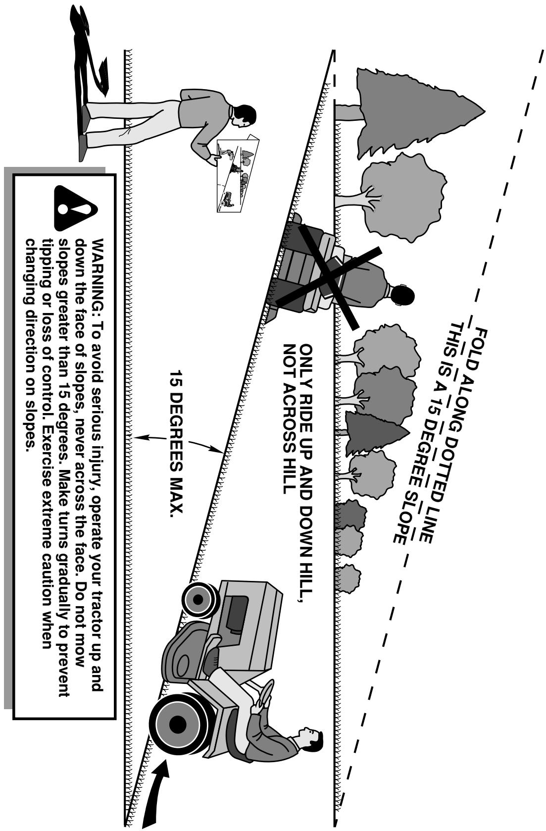
SUGGESTED GUIDE FOR SIGHTING SLOPES FOR SAFE OPERATION
SERVICE NOTES
SERVICE NOTES


- Husqvarna®
- 917.240462
- (YTH20K46)
- WARNING
- GENERAL OPERATION
- SLOPE OPERATION
- CHILDREN
- TOWING
- SERVICE
- SAFE HANDLING OF GASOLINE
- GENERAL SERVICE
- CUSTOMER RESPONSIBILITIES
- UNASSEMBLED PARTS
- ASSEMBLY
- TOOLS REQUIRED FOR ASSEMBLY
- TO REMOVE TRACTOR FROM CARTON
- UNPACK CARTON
- BEFORE REMOVING TRACTOR FROM SKID
- TO CHECK BATTERY (See Fig. 1)
- ADJUST SEAT (See Fig. 2)
- TO ROLL TRACTOR OFF SKID (See Operation section for location and function of controls)
- CHECK TIRE PRESSURE
- CHECK DECK LEVELNESS
- CHECK FOR PROPER POSITION OF ALL BELTS
- CHECK BRAKE SYSTEM
- √ CHECKLIST
- OPERATION
- KNOW YOUR TRACTOR
- READ THIS OWNER'S MANUAL AND SAFETY RULES BEFORE OPERATING YOUR TRACTOR
- HOW TO USE YOUR TRACTOR
- TO SET PARKING BRAKE (See Fig. 4)
- STOPPING (See Fig. 5)
- GROUND DRIVE -
- TO USE THROTTLE CONTROL (D) (See Fig. 6)
- TO MOVE FORWARD AND BACKWARD (See Fig. 7)
- TO USE CRUISE CONTROL (J) (See Fig. 7)
- SYSTEM CHARACTERISTICS
- TO ADJUST MOWER CUTTING HEIGHT (See Fig. 8)
- TO ADJUST GAUGE WHEELS (See Fig. 9)
- TO OPERATE MOWER (See Fig. 10)
- REVERSE OPERATION SYSTEM (ROS) (See Fig. 11)
- USING THE REVERSE OPERATION SYSTEM -
- TO OPERATE ON HILLS
- TO TRANSPORT (See Figs. 3 and 12)
- TOWING CARTS AND OTHER ATTACHMENTS
- SERVICE REMINDER/HOUR METER
- BEFORE STARTING THE ENGINE
- CHECK ENGINE OIL LEVEL
- ADD GASOLINE
- TO START ENGINE (See Fig. 3)
- PURGE TRANSMISSION
- MOWING TIPS
- MAINTENANCE
- GENERAL RECOMMENDATIONS
- BEFORE EACH USE
- TRACTOR
- BRAKE OPERATION
- TIRES
- OPERATOR PRESENCE SYSTEM AND REVERSE OPERATION SYSTEM (ROS) (See Fig. 14)
- CHECK OPERATOR PRESENCE SYSTEM
- CHECK REVERSE OPERATION (ROS) SYSTEM
- BLADE CARE
- BLADE REMOVAL (See Fig. 15)
- BATTERY
- TO CLEAN BATTERY AND TERMINALS
- V-BELTS
- TRANSAXLE COOLING
- TRANSAXLE PUMP FLUID
- ENGINE
- LUBRICATION
- TO CHANGE ENGINE OIL (See Fig. 16)
- ENGINE OIL FILTER
- ENGINE COOLING SYSTEM
- CLEAN AIR SCREEN
- AIR FILTER
- MUFFLER
- SPARK PLUGS
- IN-LINE FUEL FILTER (See Fig. 17)
- DECK WASHOUT PORT (See Fig. 18)
- CLEANING
- SERVICE AND ADJUSTMENTS
- WARNING: TO AVOID SERIOUS INJURY, BEFORE PERFORMING ANY SERVICE OR ADJUSTMENTS:
- TO REMOVE MOWER (See Fig. 20)
- TO INSTALL MOWER (See Fig. 21-25)
- TO LEVEL MOWER
- VISUAL SIDE-TO-SIDE ADJUSTMENT (See Fig. 26)
- PRECISION SIDE-TO-SIDE ADJUSTMENT (See Fig. 27)
- FRONT-TO-BACK ADJUSTMENT (See Figs. 28 & 29)
- TO REPLACE MOWER BLADE DRIVE BELT (See Fig. 30)
- BELT REMOVAL -
- BELT INSTALLATION -
- TO CHECK BRAKE
- TO REPLACE MOTION DRIVE BELT (See Fig. 31)
- FRONT WHEEL TOE-IN/CAMBER
- TO REMOVE WHEEL FOR REPAIRS (See Fig. 32)
- TO START ENGINE WITH A WEAK BATTERY (See Fig. 33)
- TO ATTACH JUMPER CABLES -
- TO REMOVE CABLES, REVERSE ORDER -
- REPLACING BATTERY (See Fig. 34)
- TO REPLACE HEADLIGHT BULB
- INTERLOCKS AND RELAYS
- TO REPLACE FUSE
- TO REMOVE HOOD AND GRILL ASSEMBLY (See Fig. 35)
- TO ADJUST THROTTLE CONTROL CABLE
- TO ADJUST CHOKE CONTROL
- TO ADJUST CARBURETOR
- TRANSMISSION
- REMOVAL/REPLACEMENT
- FUEL SYSTEM
- ENGINE OIL
- CYLINDER(S)
- OTHER
- TRACTOR -- MODEL NUMBER 917.240462, PRODUCT NO. YTH20K46 SCHEMATIC
- TRACTOR -- MODEL NUMBER 917.240462, PRODUCT NO. YTH20K46 ELECTRICAL
- TRACTOR -- MODEL NUMBER 917.240462, PRODUCT NO. YTH20K46 CHASSIS
- TRACTOR -- MODEL NUMBER 917.240462, PRODUCT NO. YTH20K46 DRIVE
- TRACTOR -- MODEL NUMBER 917.240462, PRODUCT NO. YTH20K46 ENGINE
- TRACTOR -- MODEL NUMBER 917.240462, PRODUCT NO. YTH20K46 STEERING ASSEMBLY
- TRACTOR -- MODEL NUMBER 917.240462, PRODUCT NO. YTH20K46 MOWER DECK
- TRACTOR -- MODEL NUMBER 917.240462, PRODUCT NO. YTH20K46 MOWER LIFT
- TRACTOR -- MODEL NUMBER 917.240462, PRODUCT NO. YTH20K46 SEAT ASSEMBLY
- TRACTOR -- MODEL NUMBER 917.240462, PRODUCT NO. YTH20K46 DECALS
- TRACTOR -- MODEL NUMBER 917.240462, PRODUCT NO. YTH20K46 TUFFTORQ TRANSAXLE MODEL NUMBER K46BT
- MODEL K46BT 7A646084180
- TRACTOR - - MODEL NUMBER 917.240462, PRODUCT NO. YTH20K46 KOHL ENGINE - MODEL NO. SV600-0212
- SERVICE NOTES
Marque : HUSQVARNA
Modèle : YTH 20K46
Catégorie : Tracteur de jardin