
IPL - Tondeuse autoportée HUSQVARNA - Notice d'utilisation et mode d'emploi gratuit
Retrouvez gratuitement la notice de l'appareil IPL HUSQVARNA au format PDF.

| Type de produit | Tondeuse autoportée |
| Marque | Husqvarna |
| Modèle | IPL (LTH130) |
| Moteur | Briggs & Stratton 13 CV (13 HP) |
| Capacité du réservoir | 7,6 L (2 gallons) |
| Type d'huile moteur | SAE 30 (au-dessus de 0°C) / SAE 5W-30 (en dessous) |
| Capacité d'huile (sans filtre) | 1,42 L (3 pintes) |
| Bougie | Champion RJ19LM (écartement 0,76 mm) |
| Transmission | Hydrostatique |
| Vitesse avant | 0 - 9,2 km/h (0-5,7 mph) |
| Vitesse arrière | 0 - 4,3 km/h (0-2,7 mph) |
| Largeur de coupe | 107 cm (42 pouces) |
| Hauteur de coupe | 38 - 102 mm (1,5-4 pouces) |
| Pression des pneus avant | 0,97 bar (14 psi) |
| Pression des pneus arrière | 0,83 bar (12 psi) |
| Batterie | 12 V, 25 Ah |
| Système de charge | 3 A (batterie) / 5 A (phares) |
| Poids (estimation) | Environ 200 kg |
| Dimensions (L x l x H, estimation) | 175 x 120 x 115 cm |
| Sécurité | Coupe-circuit de présence, frein de stationnement, arrêt des lames en recul |
| Entretien moteur | Vidange d'huile toutes les 25 h, filtre à air tous les 100 h, bougie par saison |
| Accessoires inclus | Plaque mulching, clés, manuel |
FOIRE AUX QUESTIONS - IPL HUSQVARNA
Questions des utilisateurs sur IPL HUSQVARNA
0 question sur cet appareil. Repondez a celles que vous connaissez ou posez la votre.
Poser une nouvelle question sur cet appareil
Téléchargez la notice de votre Tondeuse autoportée au format PDF gratuitement ! Retrouvez votre notice IPL - HUSQVARNA et reprennez votre appareil électronique en main. Sur cette page sont publiés tous les documents nécessaires à l'utilisation de votre appareil IPL de la marque HUSQVARNA.
MODE D'EMPLOI IPL HUSQVARNA
4C++1301
HcLTH1304
Owner's Manual
I. GENERAL OPERATION
- Read, understand, and follow all instructions in the manual and on the machine before starting.
- Only allow responsible adults, who are familiar with the instructions, to operate the machine.
- Clear the area of objects such as rocks, toys, wire, etc., which could be picked up and thrown by the blade.
- Be sure the area is clear of other people before mowing. Stop machine if anyone enters the area.
- Never carry passengers.
- Do not mow in reverse unless absolutely necessary. Always look down and behind before and while backing.
- Be aware of the mower discharge direction and do not point it at anyone. Do not operate the mower without either the entire grass catcher or the guard in place.
Slow down before turning. - Never leave a running machine unattended. Always turn off blades, set parking brake, stop engine, and remove keys before dismounting.
- Turn off blades when not mowing.
- Stop engine before removing grass catcher or unclogging chute.
Mow only in daylight or good artificial light. - Do not operate the machine while under the influence of alcohol or drugs.
Watch for traffic when operating near or crossing roadways. - Use extra care when loading or unloading the machine into a trailer or truck.
II. SLOPE OPERATION
Slopes are a major factor related to loss-of-control and tipover accidents, which can result in severe injury or death. All slopes require extra caution. If you cannot back up the slope or if you feel uneasy on it, do not mow it.
DO:
Mow up and down slopes, not across.
- Remove obstacles such as rocks, tree limbs, etc.
- Watch for holes, ruts, or bumps. Uneven terrain could overturn the machine. Tall grass can hide obstacles.
Use slow speed. Choose a low gear so that you will not have to stop or shift while on the slope.
- Follow the manufacturer's recommendations for wheel weights or counterweights to improve stability.
- Use extra care with grass catchers or other attachments. These can change the stability of the machine.
- Keep all movement on the slopes slow and gradual. Do not make sudden changes in speed or direction.
- Avoid starting or stopping on a slope. If tires lose traction, disengage the blades and proceed slowly straight down the slope.
DO NOT:
- Do not turn on slopes unless necessary, and then, turn slowly and gradually downhill, if possible.
- Do not mow near drop-offs, ditches, or embankments. The mower could suddenly turn over if a wheel is over the edge of a cliff or ditch, or if an edge caves in.
- Do not mow on wet grass. Reduced traction could cause sliding.
- Do not try to stabilize the machine by putting your foot on the ground.
Do not use grass catcher on steep slopes.
III. CHILDREN
Tragic accidents can occur if the operator is not alert to the presence of children. Children are often attracted to the machine and the mowing activity. Never assume that children will remain where you last saw them.
- Keep children out of the mowing area and under the watchful care of another responsible adult.
- Be alert and turn machine off if children enter the area.
Before and when backing, look behind and down for small children. - Never carry children. They may fall off and be seriously injured or interfere with safe machine operation.
- Never allow children to operate the machine.
- Use extra care when approaching blind corners, shrubs, trees, or other objects that may obscure vision.
IV. SERVICE
Use extra care in handling gasoline and other fuels. They are flammable and vapors are explosive.
Use only an approved container.
- Never remove gas cap or add fuel with the engine running. Allow engine to cool before refueling. Do not smoke.
- Never refuel the machine indoors.
- Never store the machine or fuel container inside where there is an open flame, such as a water heater.
- Never run a machine inside a closed area.
- Keep nuts and bolts, especially blade attachment bolts, tight and keep equipment in good condition.
- Never tamper with safety devices. Check their proper operation regularly.
- Keep machine free of grass, leaves, or other debris build-up. Clean oil or fuel spillage. Allow machine to cool before storing.
- Stop and inspect the equipment if you strike an object. Repair, if necessary, before restarting.
- Never make adjustments or repairs with the engine running.
- Grass catcher components are subject to wear, damage, and deterioration, which could expose moving parts or allow objects to be thrown. Frequently check components and replace with manufacturer's recommended parts, when necessary.
- Mower blades are sharp and can cut. Wrap the blade(s) or wear gloves, and use extra caution when servicing them.
- Check brake operation frequently. Adjust and service as required.

Look for this symbol to point out important safety precautions. It means CAUTION!!! BECOME ALERT!!! YOUR SAFETY IS INVOLVED.

CAUTION: Always disconnect spark plug wire and place wire where it cannot contact spark plug in order to prevent accidental starting when setting up, transporting, adjusting or making repairs.

WARNING

The engine exhaust from this product contains chemicals known to the State of California to cause cancer, birth defects, or other reproductive harm.
CONGRATULATIONS on your purchase of a new tractor. It has been designed, engineered and manufactured to give you the best possible dependability and performance.
Should you experience any problem you cannot easily remedy, please contact your nearest authorized service center/department. We have competent, well-trained technicians and the proper tools to service or repair this unit.
Please read and retain this manual. The instructions will enable you to assemble and maintain your unit properly. Always observe the "SAFETY RULES".
MODEL
NUMBER LTH130
SERIAL
NUMBER
DATEOFPURCHASE
THE MODEL AND SERIAL NUMBERS WILL BE FOUND ON A PLATE UNDER THE SEAT.
YOU SHOULD RECORD BOTH SERIAL NUMBER AND DATE OF PURCHASE AND KEEP IN A SAFE PLACE FOR FUTURE REFERENCE.
CUSTOMER RESPONSIBILITIES
- Read and observe the safety rules.
- Follow a regular schedule in maintaining, caring for and using your unit.
- Follow the instructions under "Customer Responsibilities" and "Storage" sections of this owner's manual.
PRODUCT SPECIFICATIONS
| HORSEPOWER: | 13.0 |
| GASOLINE CAPACITY AND TYPE: | 2 GALLONS UNLEADED REGULAR |
| OIL TYPE (API-SF/SG): | SAE 30 (above 32°F) SAE 5W-30 (below 32°F) |
| OIL CAPACITY: | W/O FILTER: 3 PINTS |
| SPARK PLUG: (GAP: .030") | CHAMPION RJ19LM |
| VALVE CLEARANCE: | INTAKE: .005" - .007" EXHAUST: .009" - .011" |
| GROUND SPEED (MPH): | FORWARD: 0 - 5.70 REVERSE: 0 - 2.70 |
| TIRE PRESSURE: | FRONT: 14 PSI REAR: 12 PSI |
| CHARGING SYSTEM: | 3 AMPS BATTERY 5 AMPS HEADLIGHTS |
| BATTERY: | AMP/HR: 25 MIN. CCA: 190 CASE SIZE: U1R |
| BLADE BOLT TORQUE: | 30-35 FT. LBS. |
WARNING: This tractor is equipped with an internal combustion engine and should not be used on or near any unimproved forest-covered, brush-covered or grass-covered land unless the engine's exhaust system is equipped with a spark arrester meeting applicable local or state laws (if any). If a spark arrester is used, it should be maintained in effective working order by the operator.
A spark arrester for the muffler is available through your nearest authorized service center/department (See REPAIR PARTS section of this manual).
SAFETY RULES 2
3 PRODUCT SPECIFICATIONS 3
CUSTOMER RESPONSIBILITIES 3, 14-17
ASSEMBLY 6-9
OPERATION 10-13
MAINTENANCE SCHEDULE 14
SERVICE AND ADJUSTMENTS 19-23
STORAGE 24
TROUBLESHOOTING 25-26
REPAIR PARTS - TRACTOR 28-45
WARRANTY 57
INDEX
A
Adjustments: Brake 20
Carburetor 23
Mower Front-To-Back 19
Side-To-Side 19
Throttle Control Cable 22
Air Filter, Engine. 17
Air Screen, Engine 17
Assembly 6-9
B
Battery: Charging 7
Cleaning 16
Levels. 7,16
Starting with Weak Battery. 21
Storage 24
Terminals 16
Belt: Motion Drive Removal/Replacement 20
Mower Belt(s) Removal/Replacement 20
Blade: Sharpening 15
Replacement 15
Brake Adjustment 20
C
Carburetor Adjustment 23
Controls, Tractor 10
Customer Responsibilities 14-17
Engine: Air Filter. 16
Air Screen 17
Cooling Fins 17
Engine Oil 12,16
Fuel Filter 17
Spark Plug(s) 17
Tractor: Battery. 16
Blade 15
Lubrication Chart 14
Maintenance Schedule 14
Tire Care 7.15.21
Transaxle 16
Cutting Height, Mower 11
E
Electrical:
Interlocks and Relays: 22
Schematic 27
Wiring Diagram 28
Engine:
Air Filter. 16
Air Screen 17
Cooling Fins 17
Oil Change 16
Oil Level 12
Oil Type 12,16
Preparation 12
Starting 13
Storage 24
F
Filter:
Air Filter. 16
Fuel 17
Fuel:
Type 12
Storage 24
Fuse 22
H
Hood Removal/Installation 22
L
Leveling Mower Deck. 19
Lubrication:
Chart 14
Engine 16
M
Maintenance Schedule 14
Mower:
Adjustment, Front-to-Back 19
Adjustment, Side-to-Side 19
Blade Replacement 15
Blade Sharpening 15
Cutting Height 11
Installation 18
Operation 12
Removal 18
Mowing Tips 13
Muffler 17
Spark Arrester 3,38
0
Oil:
Cold Weather Conditions 12,16
Engine 16
Storage 24
Operation 10-13
Operating Mower 12
Options:
Spark Arrester 3,38
P
Parking Brake 10-11
Parts Bag 5
Parts, Replacement/Repair 28-45
Product Specifications. 2
R
Repair Parts 28-45
s
Safety Rules 2
Seat 7
Service and Adjustments 19-23
Carburetor 23
Fuse 22
Hood Removal/Installation 22
Motion Drive Belt Removal/Replacement 20
Mower Belt(s) Removal/Replacement 20
Mower Adjustment
Front-to-Back 21
Side-to-Side 21
Mower Removal/Installation 183
Tire Care 7,15,21
Slope Guide Sheet 56
Spark Plug(s) 17
Specifications 3
Starting the Engine 13
Steering Wheel 6,21
Stopping the Tractor 11
Storage 24
T
Throttle Control Cable Adjustment .... 22
Tires. 7,15,21
Troubleshooting Chart 25-26
Transaxle 16
W
Warranty. 57
Wiring Diagram 28
Wiring Schematic 27
Parts Bag contents shown full size
e
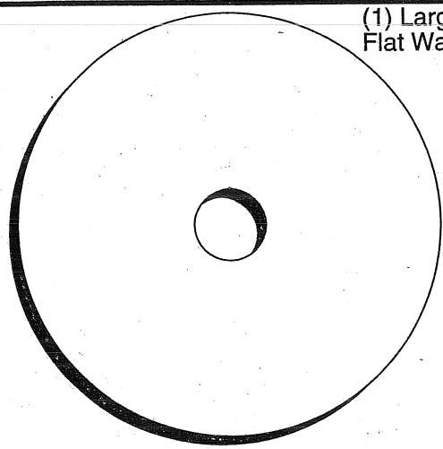
Flat Washer

(3) Tinnerman
Clips

(1) Locknut
3/8-24

(1) Locknut
5/16-18
(1) Knob

(1) Washer 17 / 32 × 1 - 3 / 16 × 12 Gauge
(2) Screws
10x5/8

(2) Washers
3/16 x 3/4 x
16 Gauge

12x - 1 = 12x( 1 - x)
(2) Hex Bolts
1/4-20 x 3/4
(2) Lock
Washers
10
(2) Weld
Nuts #10
(2) Hex Bolts
1/4-20 x 3/4

(2) Hex Nuts
/4-20

(2) Washers
9/32 x 5/8
x 16 Ga.

(2) Lock
Washers 1/4
Parts packed separately in carton
Seat
Steering
Wheel
Mulcher
Plate

Manual

Parts Bag
Parts bag contents not shown full size
Steering
Wheel
Insert

(2) Latch Hook
Assemblies
Steering Wheel
Adapter

Steering
sleeve

Steering
Extension
Shaft
Slope Sheet

(2) Keys
Your new tractor has been assembled at the factory with exception of those parts left unassembled for shipping purposes. To ensure safe and proper operation of your tractor all parts and hardware you assemble must be tightened securely. Use the correct tools as necessary to insure proper tightness.
TOOLS REQUIRED FOR ASSEMBLY
A socket wrench set will make assembly easier. Standard wrench sizes are listed.
(2) 7/16" wrenches Phillips Screwdriver
(2) 1 / 2'' wrench Tire pressure gauge
(1) 9/16" wrench Utility knife
When right or left hand is mentioned in this manual, it means when you are in the operating position (seated behind the steering wheel).
TO REMOVE TRACTOR FROM CARTON
UNPACK CARTON
- Remove all accessible loose parts and parts cartons from carton (See page 5).
- Cut, from top to bottom, along lines on all four corners of carton, and lay panels flat.
- Check for any additional loose parts or cartons and remove.
BEFORE ROLLING TRACTOR OFF SKID
ATTACH STEERING WHEEL (See Fig. 1)
PREASSEMBLE SLEEVE TO STEERING WHEEL (See Fig. 1 Inset)
- Install sleeve retainer clips, evenly spaced around steering wheel hub, with formed tabs toward the outside of hub.
- Press or lightly tap retainer clips fully onto steering wheel hub.
- Press steering sleeve fully onto steering wheel hub and clips.
ASSEMBLE EXTENSION SHAFT
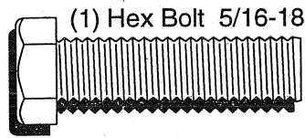
- Slide extension shaft onto lower steering shaft. Align mounting holes in extension and lower shafts and install 5/16 hex bolt and locknut. Tighten securely.
IMPORTANT: TIGHTEN BOLT AND NUT SECURELY TO 18-22 FT. LBS TORQUE.
INSTALL STEERING WHEEL
- Position front wheels of the tractor so they are pointing straight forward.
- Slide steering wheel adapter onto steering shaft extension.
- Position steering wheel and sleeve assembly so cross bars are horizontal (left to right) and slide onto adapter.
- Assemble large flat washer and 3/8-24 locknut and tighten securely.
- Snap steering wheel insert into center of steering wheel.
- Remove protective plastic from tractor hood and grill.
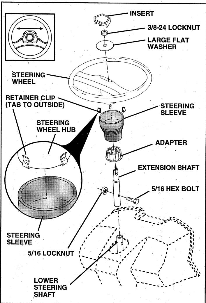
FIG. 1
IMPORTANT: CHECK FOR AND REMOVE ANY STAPLES IN SKID THAT MAY PUNCTURE TIRES WHERE TRACTOR IS TO ROLL OFF SKID.
TO ROLL TRACTOR OFF SKID (See Operation section for location and function of controls)
- Press lift lever plunger and raise attachment lift lever to its highest position.
- Release parking brake by depressing clutch/brake pedal.
- Place freewheel control in freewheeling position to disengage transmission (See "TO TRANSPORT" in the Operation section of this manual).
Roll tractor backwards off skid. - Remove banding holding discharge guard up against tractor.
CONNECT BATTERY (See Figs. 2 and 3)

CAUTION: Do not short battery terminals. Before connecting battery, remove metal bracelets, wristwatch bands, rings, etc.
Positive terminal must be connected first to prevent sparking from accidental grounding.
- Remove cardboard packing from seat pan and lift seat pan to raised position.
- Open battery box door.
- Remove terminal protective caps and discard.
If this battery is put into service after month and year indicated on label (label located between terminals) charge battery for minimum of one hour at 6-10 amps. - First connect RED battery cable to positive (+) terminal with hex bolt, flat washer, lock washer and hex nut as shown. Tighten securely.
- Connect BLACK grounding cable to negative (-) terminal with remaining hex bolt, flat washer, lock washer and hex nut. Tighten securely.
- Close battery box door.
Open battery box door for:
- Inspection for secure connections (to tighten hardware).
Inspection for corrosion. - Testing battery.
- Jumping (if required).
Periodic charging.
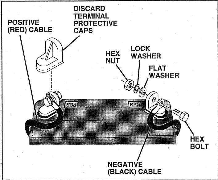
FIG. 2
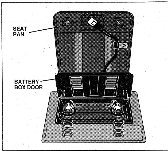
FIG. 3
INSTALL SEAT (See Fig. 4)
Adjust seat before tightening adjustment knob.
- Remove cardboard packing on seat pan.
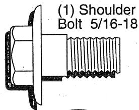
- Place seat on seat pan and assemble shoulder bolt.
- Assemble adjustment knob and flat washer loosely. Do not tighten.
- Tighten shoulder bolt securely.
Lower seat into operating position and sit on seat. - Slide seat until a comfortable position is reached which allows you to press clutch/brake pedal all the way down.
Get off seat without moving its adjusted position. - Raise seat and tighten adjustment knob securely.
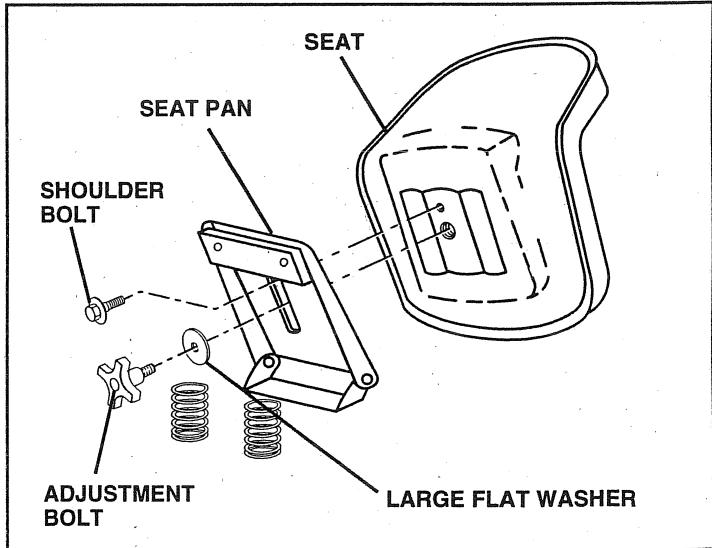
FIG. 4
INSTALL MULCHER PLATE (See Figs. 5 and 6)
- Install two latch hooks to mulcher plate using screw, washer, lock washer, and weld nut as shown.
NOTE: Pre-assemble weld nut to latch hook by inserting weld nut from the top with hook pointing down.
- Tighten hardware securely.
- Raise and hold deflector shield in upright position.
- Place front of mulcher plate over front of mower deck opening and slide into place, as shown.
- Hook front latch into hole on front of mower deck.
- Hook rear latch into hole on back of mower deck.

CAUTION: Do not remove discharge guard from mower. Raise and hold guard when attaching mulcher plate and allow it to rest on plate while in operation.
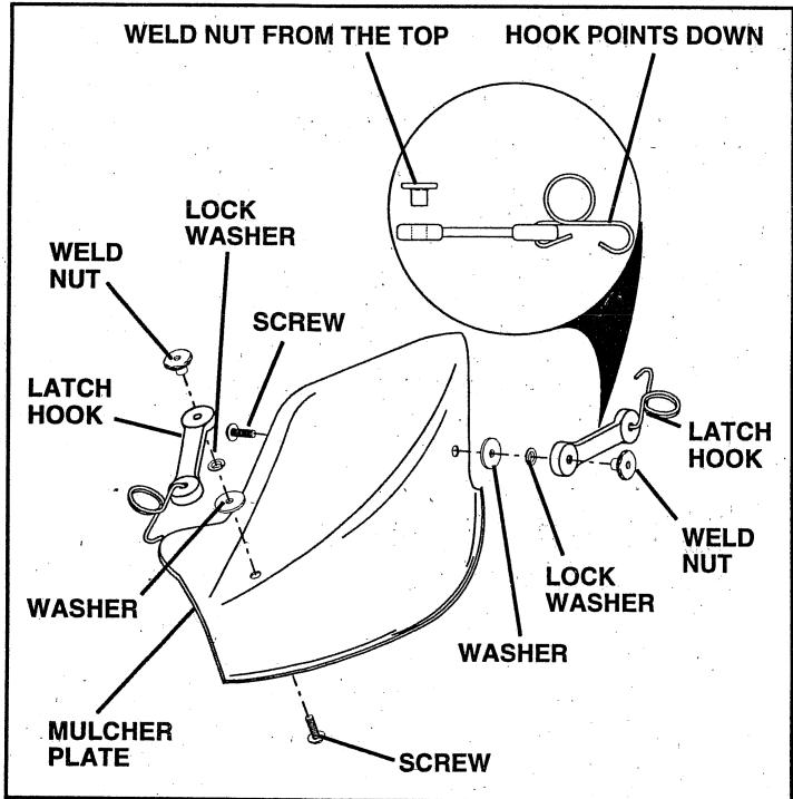
FIG. 5
TO CONVERT TO BAGGING OR DISCHARGING
Simply remove mulcher plate and store in a safe place. Your mower is now ready for discharging or installation of optional grass catcher accessory.
NOTE: It is not necessary to change blades. The mulcher blades are designed for discharging and bagging also.
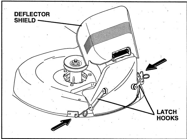
FIG. 6
ASSEMBLY
CHECK TIRE PRESSURE
The tires on your tractor were overinflated at the factory for shipping purposes. Correct tire pressure is important for best cutting performance.
- Reduce tire pressure to PSI shown in "PRODUCT SPECIFICATIONS" on page 3 of this manual.
CHECK DECK LEVELNESS
For best cutting results, mower housing should be properly leveled. See "TO LEVEL MOWER HOUSING" in the Service and Adjustments section of this manual.
CHECK FOR PROPER POSITION OF ALL BELTS
See the figures that are shown for replacing motion and mower blade drive belts in the Service and Adjustments section of this manual. Verify that the belts are routed correctly.
CHECK BRAKE SYSTEM
After you learn how to operate your tractor, check to see that the brake is properly adjusted. See "TO ADJUST BRAKE" in the Service and Adjustments section of this manual.
√CHECKLIST
BEFORE YOU OPERATE AND ENJOY YOUR NEW TRACTOR, WE WISH TO ASSURE THAT YOU RECEIVE THE BEST PERFORMANCE AND SATISFACTION FROM THIS QUALITY PRODUCT.
PLEASE REVIEW THE FOLLOWING CHECKLIST:
All assembly instructions have been completed.
No remaining loose parts in carton.
Battery is properly prepared and charged. (Minimum 1 hour at 6 amps).
Seat is adjusted comfortably and tightened securely.
√ All tires are properly inflated. (For shipping purposes, the tires were overinflated at the factory).
- Be sure mower deck is properly leveled side-to-side/ front-to-rear for best cutting results. (Tires must be properly inflated for leveling).
- Check mower and drive belts. Be sure they are routed properly around pulleys and inside all belt keepers.
- Check wiring. See that all connections are still secure and wires are properly clamped.
Before driving tractor, be sure freewheel control is in drive position.
WHILE LEARNING HOW TO USE YOUR TRACTOR, PAY EXTRA ATTENTION TO THE FOLLOWING IMPORTANT ITEMS:
✓ Engine oil is at proper level.
Fuel tank is filled with fresh, clean, regular unleaded gasoline.
Become familiar with all controls - their location and function. Operate them before you start the engine.
Be sure brake system is in safe operating condition.
It is important to purge the transmission before operating your tractor for the first time. Follow proper starting and transmission purging instructions (See "TO START ENGINE" and "PURGE TRANSMISSION" in the Operation section of this manual).
These symbols may appear on your tractor or in literature supplied with the product. Learn and understand their meaning.

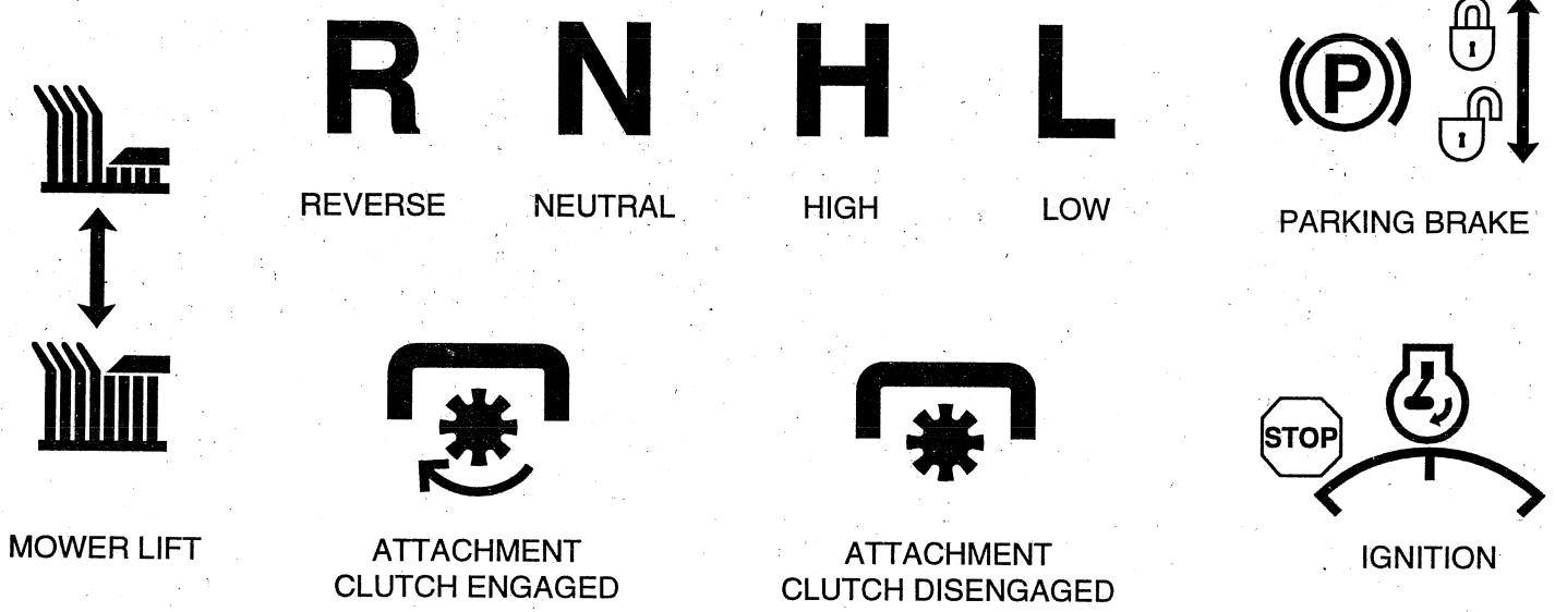

DANGER, KEEP HANDS AND FEET AWAY
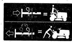
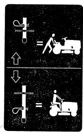
HYDROSTATIC FREE WHEEL (Hydro Models only)
KNOW YOUR TRACTOR
READ THIS OWNER'S MANUAL AND SAFETY RULES BEFORE OPERATING YOUR TRACTOR
Compare the illustrations with your tractor to familiarize yourself with the locations of various controls and adjustments. Save this manual for future reference.
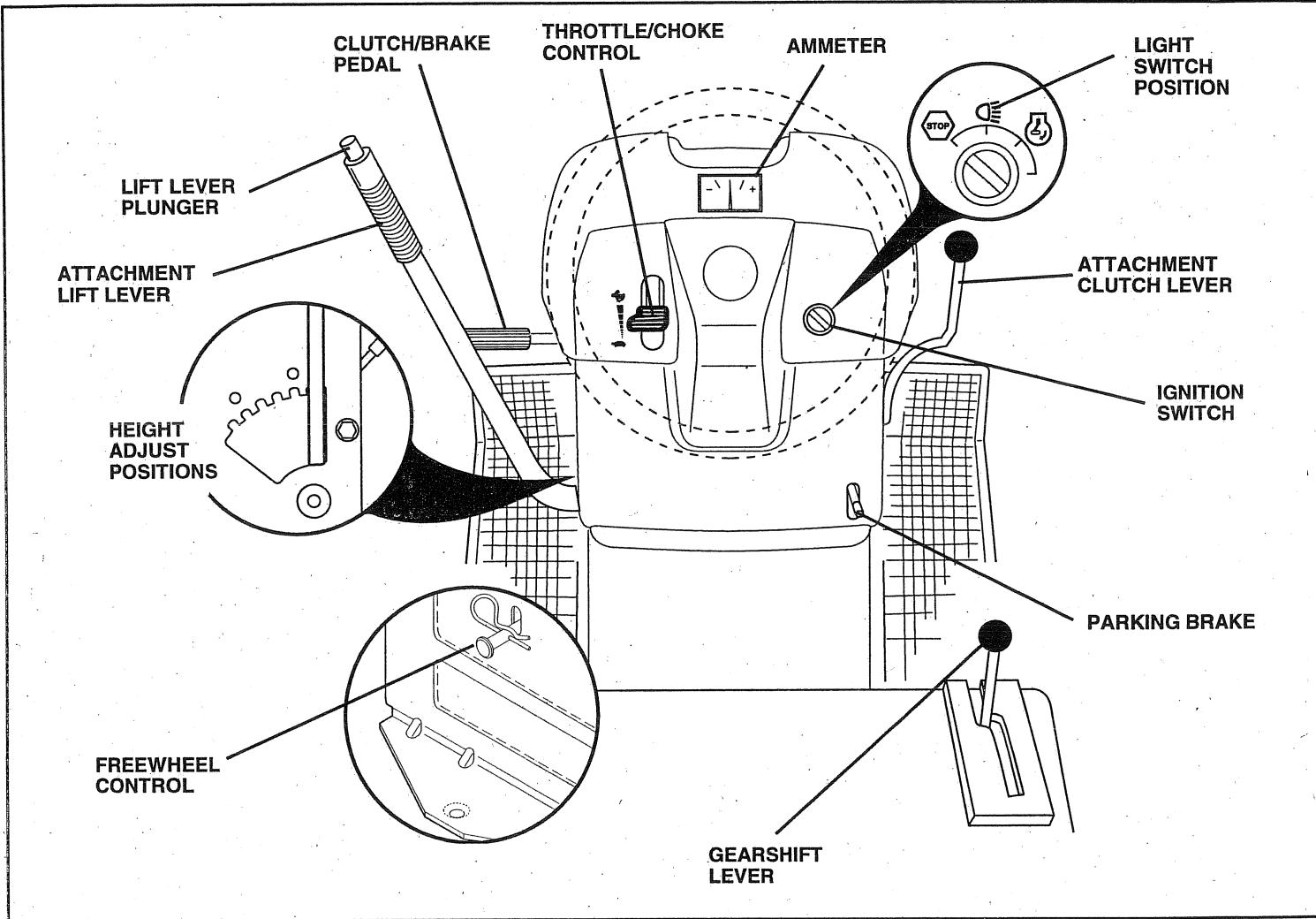
FIG. 7
Our tractors conform to the safety standards of the American National Standards Institute.
ATTACHMENT CLUTCH LEVER: Used to engage the mower blades, or other attachments mounted to your tractor.
LIGHT SWITCH POSITION: Turns the headlights on.
THROTTLE/CHOKE CONTROL: Used for starting and controlling engine speed.
CLUTCH/BRAKE PEDAL: Used for declutching and braking the tractor and starting the engine.
PARKING BRAKE: Locks clutch/brake pedal into the brake position.
FREEWHEEL CONTROL: Disengages transmission for pushing or slowly towing the tractor with the engine off.
AMMETER: Indicates charging (+) or discharging (-) of battery.
GEARSHIFT LEVER: Selects the speed and direction of tractor.
ATTACHMENT LIFT LEVER: Used to raise, lower, and adjust the mower deck or other attachments mounted to your tractor.
LIFT LEVER PLUNGER: Used to release attachment lift lever when changing its position.
IGNITION SWITCH: Used for starting and stopping the engine.

The operation of any tractor can result in foreign objects thrown into the eyes, which can result in severe eye damage. Always wear safety glasses or eye shields while operating your tractor or performing any adjustments or repairs. We recommend a wide vision safety mask over the spectacles or standard safety glasses.
HOW TO USE YOUR TRACTOR
TO SET PARKING BRAKE (See Fig. 8)
Your tractor is equipped with an operator presence sensing switch. When engine is running, any attempt by the operator to leave the seat without first setting the parking brake will shut off the engine.
- Depress clutch/brake pedal into full "BRAKE" position and hold.
- Place parking brake lever in "ENGAGED" position and release pressure from clutch/brake pedal. Pedal should remain in "BRAKE" position. Make sure parking brake will hold tractor secure.
STOPPING (See Fig. 8)
MOWER BLADES -
- Move attachment clutch lever to "DISENGAGED" position.
GROUND DRIVE - - Depress clutch/brake pedal into full "BRAKE" position.
- Move motion control lever to neutral (N) position.
IMPORTANT: THE MOTION CONTROL LEVER DOES NOT RETURN TO NEUTRAL (N) POSITION WHEN THE CLUTCH/BRAKE PEDAL IS DEPRESSED. ENGINE -
- Move throttle control to slow ( ) position.
NOTE: Failure to move throttle control to slow ( ) position and allowing engine to idle before stopping may cause engine to "backfire".
- Turn ignition key to "OFF" position and remove key. Always remove key when leaving tractor to prevent unauthorized use.
- Never use choke to stop engine.
NOTE: Under certain conditions when tractor is standing idle with the engine running, hot engine exhaust gases may cause "browning" of grass. To eliminate this possibility, always stop engine when stopping tractor on grass areas.

CAUTION: Always stop tractor completely, as described above, before leaving the operator's position; to empty grass catcher, etc.
TO USE THROTTLE CONTROL (See Fig. 8)
Always operate engine at full throttle.
- Operating engine at less than full throttle reduces the battery charging rate.
Full throttle offers the best bagging and mower performance.
TO MOVE FORWARD AND BACKWARD (See Fig. 8)
The direction and speed of movement is controlled by the motion control lever.
- Start tractor with motion control lever in neutral (N) position.
- Release parking brake and clutch/brake pedal.
- Slowly move motion control lever to desired position.
TO ADJUST MOWER CUTTING HEIGHT (See Fig. 8)
The position of the attachment lift lever determines the cutting height.
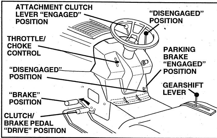
FIG. 8
- Grasp lift lever.
- Press plunger with thumb and move lever to desired position.
The cutting height range is approximately 1-1/2 to 4^ . The heights are measured from the ground to the blade tip with the engine not running. These heights are approximate and may vary depending upon soil conditions, height of grass and types of grass being mowed.
- The average lawn should be cut to approximately 2-1/2 inches during the cool season and to over 3 inches during hot months. For healthier and better looking lawns, mow often and after moderate growth.
- For best cutting performance, grass over 6 inches in height should be mowed twice. Make the first cut relatively high; the second to desired height.
TO OPERATE MOWER (See Fig. 9)
Your tractor is equipped with an operator presence sensing switch. Any attempt by the operator to leave the seat with the engine running and the attachment clutch engaged will shut off the engine.
- Select desired height of cut.
- Start mower blades by engaging attachment clutch control.
TO STOP MOWER BLADES - disengage attachment clutch control.

CAUTION: Do not operate the mower without either the entire grass catcher, on mowers so equipped, or the discharge guard in place.
TO OPERATE ON HILLS

CAUTION: Do not drive up or down hills with slopes greater than 15^ and do not drive across any slope.
- Choose the slowest speed before starting up or down hills.
- Avoid stopping or changing speed on hills.
- If slowing is necessary, move throttle control lever to slower position.
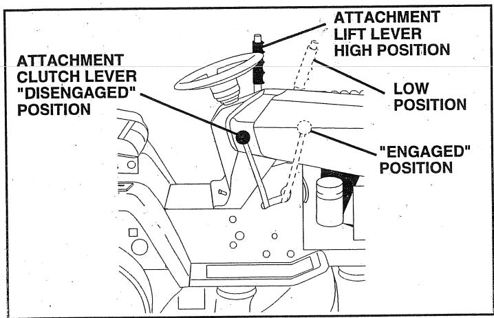
FIG. 9
- If stopping is absolutely necessary, push clutch/brake pedal quickly to brake position and engage parking brake.
- Move motion control lever to neutral (N) position.
IMPORTANT: THE MOTION CONTROL LEVER DOES NOT RETURN TO NEUTRAL (N) POSITION WHEN THE CLUTCH/BRAKE PEDAL IS DEPRESSED.
- To restart movement, slowly release parking brake and clutch/brake pedal.
- Slowly move motion control lever to slowest setting.
Make all turns slowly.
TO TRANSPORT (See Figs. 7 and 10)
When pushing or towing your tractor, be sure to disengage transmission by placing freewheel control in freewheeling position. Free wheel control is located at the rear drawbar of tractor.
- Raise attachment lift to highest position with attachment lift control.
Pull freewheel control knob out and hold in position by inserting retainer spring into forward hole of control rod. - Do not push or tow tractor at more than two (2) MPH.
To reengage transmission, reverse above procedure.
NOTE: To protect hood from damage when transporting your tractor on a truck or a trailer, be sure hood is closed and secured to tractor. Use an appropriate means of tying hood to tractor (rope, cord, etc.).
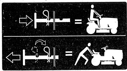
FIG. 10
BEFORE STARTING THE ENGINE CHECK ENGINE OIL LEVEL (See Fig. 15)
- The engine in your tractor has been shipped, from the factory, already filled with summer weight oil.
- Check engine oil with tractor on level ground.
-
Remove oil fill cap/dipstick and wipe clean, reinsert the dipstick and screw cap tight, wait for a few seconds, remove and read oil level. If necessary, add oil until "FULL" mark on dipstick is reached. Do not overfill.
-
For cold weather operation you should change oil for easier starting (See "OIL VISCOSITY CHART" in the Customer Responsibilities section of this manual).
- To change engine oil, see the Customer Responsibilities section in this manual.
ADD GASOLINE
- Fill fuel tank. Use fresh, clean, regular unleaded gasoline with a minimum of 87 octane. (Use of leaded gasoline will increase carbon and lead oxide deposits and reduce valve life). Do not mix oil with gasoline. Purchase fuel in quantities that can be used within 30 days to assure fuel freshness.
IMPORTANT: WHEN OPERATING IN TEMPERATURES BELOW 32^(0^) , USE FRESH, CLEAN WINTER GRADE GASOLINE TO HELP INSURE GOOD COLD WEATHER STARTING.
WARNING: Experience indicates that alcohol blended fuels (called gasohol or using ethanol or methanol) can attract moisture which leads to separation and formation of acids during storage. Acidic gas can damage the fuel system of an engine while in storage. To avoid engine problems, the fuel system should be emptied before storage of 30 days or longer. Drain the gas tank, start the engine and let it run until the fuel lines and carburetor are empty. Use fresh fuel next season. See Storage Instructions for additional information. Never use engine or carburetor cleaner products in the fuel tank or permanent damage may occur.

CAUTION: Fill to bottom of gas tank filler neck. Do not overfill. Wipe off any spilled oil or fuel. Do not store, spill or use gasoline near an open flame.
TO START ENGINE (See Fig. 7)
When starting engine for the first time or if engine has run out of fuel, it will take extra cranking time to move fuel from the tank to the engine.
- Depress clutch/brake pedal and set parking brake.
- Place motion control lever in neutral (N) position.
- Move attachment clutch to "DISENGAGED" position.
- Move throttle control lever to choke (N) position for cold engine start. For warm engine start, move throttle control to fast (E) position.
- Insert key into ignition and turn key clockwise to "START" position and release key as soon as engine starts. Do not run starter continuously for more than fifteen seconds per minute. If engine does not start after several attempts, move throttle control to fast ( ) position, wait a few minutes and try again.
- When engine starts, slowly move throttle control lever to desired running speed.
- Allow engine to warm up for a few minutes before engaging drive or attachments.
IMPORTANT: COLD STARTING FOR HYDRO (BELOW 40°F) - AFTER STARTING ENGINE AND BEFORE DRIVING, LET TRANSMISSION WARM UP FOR ONE (1) MINUTE BY PLACING MOTION CONTROL LEVER IN NEUTRAL (N) POSITION AND RELEASING CLUTCH/ BRAKE PEDAL.
NOTE: If at a high altitude (above 3000 feet) or in cold temperatures (below 32^ ), the carburetor fuel mixture may need to be adjusted for best engine performance. See "TO ADJUST CARBURETOR" in the Service and Adjustments section of this manual.
PURGE TRANSMISSION

CAUTION: Never engage or disengage freewheel lever while the engine is running.
To ensure proper operation and performance, it is recommended that the transmission be purged before operating tractor for the first time. This procedure will remove any trapped air inside the transmission which may have developed during shipping of your tractor.
IMPORTANT: SHOULD YOUR TRANSMISSION REQUIRE REMOVAL FOR SERVICE OR REPLACEMENT, IT SHOULD BE PURGED AFTER REINSTALLATION BEFORE OPERATING THE TRACTOR.
- Place tractor safely on level surface with engine off and parking brake set.
- Disengage transmission by placing freewheel control in freewheeling position (See "TO TRANSPORT" in this section of manual).
- Sitting in the tractor seat, start engine. After the engine is running, move throttle control to slow ( ) position. With motion control lever in neutral ( N) position, slowly disengage clutch/brake pedal.
- Move motion control lever to full forward position and hold for five (5) seconds. Move lever to full reverse position and hold for five (5) seconds. Repeat this procedure three (3) times.
NOTE: During this procedure there will be no movement of drive wheels. The air is being removed from hydraulic drive system.
- Move motion control lever to neutral (N) position. Shut-off engine and set parking brake.
- Engage transmission by placing freewheel control in driving position (See "TO TRANSPORT" in this section of manual).
- Sitting in the tractor seat, start engine. After the engine is running, move throttle control to half (1/2) speed. With motion control lever in neutral (N) position, slowly disengage clutch/brake pedal.
- Slowly move motion control lever forward, after the tractor moves approximately five (5) feet, slowly move motion control lever to reverse position. After the tractor moves approximately five (5) feet return the motion control lever to the neutral (N) position. Repeat this procedure with the motion control lever three (3) times.
- Your tractor is now purged and now ready for normal operation.
MOWING TIPS
- Tire chains cannot be used when the mower housing is attached to tractor.
- Mower should be properly leveled for best mowing performance. See "TO LEVEL MOWER HOUSING" in the Service and Adjustments section of this manual.
- The left hand side of mower should be used for trimming.
- Drive so that clippings are discharged onto the area that has been cut. Have the cut area to the right of the machine. This will result in a more even distribution of clippings and more uniform cutting.
-
When mowing large areas, start by turning to the right so that clippings will discharge away from shrubs, fences, driveways, etc. After one or two rounds, mow in the opposite direction making left hand turns until finished (See Fig. 11).
-
If grass is extremely tall, it should be mowed twice to reduce load and possible fire hazard from dried clippings. Make first cut relatively high; the second to the desired height.
- Do not mow grass when it is wet. Wet grass will plug mower and leave undesirable clumps. Allow grass to dry before mowing.
- Always operate engine at full throttle when mowing to assure better mowing performance and proper discharge of material. Regulate ground speed by selecting a low enough gear to give the mower cutting performance as well as the quality of cut desired.
- When operating attachments, select a ground speed that will suit the terrain and give best performance of the attachment being used.
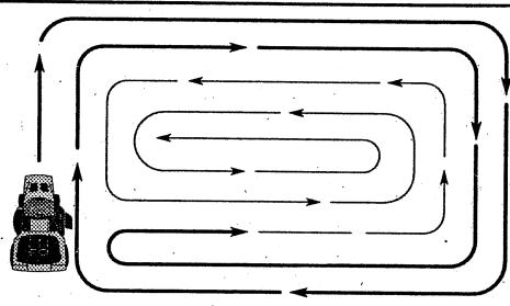
FIG. 11
MULCHING MOWING TIPS
IMPORTANT: FOR BEST PERFORMANCE, KEEP MOWER HOUSING FREE OF BUILT-UP GRASS AND TRASH. CLEAN AFTER EACH USE.
- The special mulching blade will recut the grass clippings many times and reduce them in size so that as they fall onto the lawn they will disperse into the grass and not be noticed. Also, the mulched grass will biodegrade quickly to provide nutrients for the lawn. Always mulch with your highest engine (blade) speed as this will provide the best recutting action of the blades.
- Avoid cutting your lawn when it is wet. Wet grass tends to form clumps and interferes with the mulching action. The best time to mow your lawn is the early afternoon. At this time the grass has dried and the newly cut area will not be exposed to the direct sun.
- For best results, adjust the mower cutting height so that the mower cuts off only the top one-third of the grass blades (See Fig. 12). For extremely heavy mulching, reduce your width of cut and mow slowly.
- Certain types of grass and grass conditions may require that an area be mulched a second time to completely hide the clippings. When doing a second cut, mow across or perpendicular to the first cut path.
- Change your cutting pattern from week to week. Mow north to south one week then change to east to west the next week. This will help prevent matting and graining of the lawn.
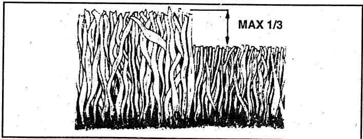
FIG. 12
CUSTOMER RESPONSIBILITIES
| MAINTENANCE SCHEDULE FILL IN DATES AS YOU COMPLETE REGULAR SERVICE | BEFORE EACHUSE FIRST 2 HOURS EVERY 8 HOURS EVERY 25 HOURS EVERY 50 HOURS EVERY 100 HOURS BEFORE STORAGE SERVICE DATES | |||||||||||
| TRA CTOR | Check Brake Operation | ✓ | ✓ | |||||||||
| Check Tire Pressure | ✓ | ✓ | ||||||||||
| Check for Loose Fasteners | ✓ | ✓7 | ✓ | |||||||||
| Sharpen/Replace Mower Blades | ✓4 | |||||||||||
| Lubrication Chart | ✓ | ✓ | ||||||||||
| Check Battery Level/Recharge | ✓6 | |||||||||||
| Clean Battery and Terminals | ✓ | ✓ | ||||||||||
| Check Transaxle Cooling | ✓ | |||||||||||
| Adjust Blade Belt(s) Tension | ✓5 | |||||||||||
| Adjust Motion Drive Belt(s) Tension | ✓5 | |||||||||||
| E N G E | Check Engine Oil Level | ✓ | ✓ | |||||||||
| Change Engine Oil | ✓ | ✓1,2,3 | ✓ | |||||||||
| Clean Air Filter | ✓2 | |||||||||||
| Clean Air Screen | ✓2 | |||||||||||
| Inspect Muffler/Spark Arrester | ✓ | |||||||||||
| Replace Oil Filter (If equipped) | ✓1,2 | |||||||||||
| Clean Engine Cooling Fins | ✓2 | . | ||||||||||
| Replace Spark Plug | ✓ | ✓ | ||||||||||
| Replace Air Filter Paper Cartridge | ✓2 | |||||||||||
| Replace Fuel Filter | ✓ | |||||||||||
1 - Change more often when operating under a heavy load or in high ambient temperatures.
2 - Service more often when operating in dirty or dusty conditions.
3 - If equipped with oil filter, change oil every 50 hours.
4 - Replace blades more often when mowing in sandy soil.
5 - If equipped with adjustable system.
6 - Not required if equipped with maintenance-free battery.
7 - Tighten front axle pivot bolt to 35 ft.-lbs. maximum.
Do not overtighten:
GENERAL RECOMMENDATIONS
The warranty on this tractor does not cover items that have been subjected to operator abuse or negligence. To receive full value from the warranty, operator must maintain tractor as instructed in this manual.
Some adjustments will need to be made periodically to properly maintain your tractor.
All adjustments in the Service and Adjustments section of this manual should be checked at least once each season.
- Once a year you should replace the spark plug, clean or replace air filter, and check blades and belts for wear. A new spark plug and clean air filter assure proper air-fuel mixture and help your engine run better and last longer.
BEFORE EACH USE
- Check engine oil level.
- Check brake operation.
- Check tire pressure.
- Check for loose fasteners.
LUBRICATION CHART
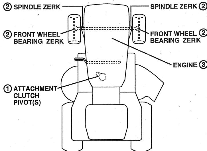
① SAE 30 OR 10W30 MOTOR OIL
(2)GENERAL PURPOSE GREASE
③ REFER TO CUSTOMER RESPONSIBILITIES "ENGINE" SECTION
IMPORTANT: DO NOT OIL OR GREASE THE PIVOT POINTS WHICH HAVE SPECIAL NYLON BEARINGS. VISCOUS LUBRICANTS WILL ATTRACT DUST AND DIRT THAT WILL SHORTEN THE LIFE OF THE SELF-LUBRICATING BEARINGS. IF YOU FEEL THEY MUST BE LUBRICATED, USE ONLY A DRY, POWDERED GRAPHITE TYPE LUBRICANT SPARINGLY.
TRACTOR
Always observe safety rules when performing any maintenance.
BRAKE OPERATION
If tractor requires more than six (6) feet stopping distance at high speed in highest gear, then brake must be adjusted. (See "TO ADJUST BRAKE" in the Service and Adjustments section of this manual).
TIRES
- Maintain proper air pressure in all tires (See "PRODUCT SPECIFICATIONS" on page 3 of this manual).
- Keep tires free of gasoline, oil, or insect control chemicals which can harm rubber.
- Avoid stumps, stones, deep ruts, sharp objects and other hazards that may cause tire damage.
BLADE CARE
For best results mower blades must be kept sharp. Replace bent or damaged blades.
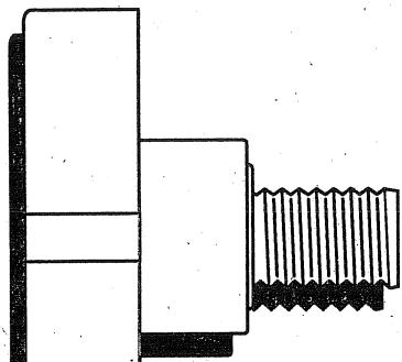
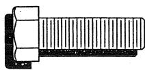
BLADE REMOVAL (See Fig. 13)
- Raise mower to highest position to allow access to blades.
- Remove hex bolt, lock washer and flat washer securing blade.
- Install new or resharpened blade with trailing edge up towards deck as shown.
- Reassemble hex bolt, lock washer and flat washer in exact order as shown.
- Tighten bolt securely (30-35 Ft. Lbs. torque).
IMPORTANT: BLADE BOLT IS GRADE 8 HEAT TREATED.
NOTE: We do not recommend sharpening blade - but if you do, be sure the blade is balanced.
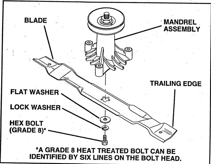
FIG. 13
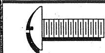
TO SHARPEN BLADE (See Fig. 14)
Care should be taken to keep the blade balanced. An unbalanced blade will cause excessive vibration and eventual damage to mower and engine.
- The blade can be sharpened with a file or on a grinding wheel. Do not attempt to sharpen while on the mower.
- To check blade balance, you will need a 5/8'' diameter steel bolt, pin, or a cone balancer. (When using a cone balancer, follow the instructions supplied with balancer).
- Slide blade on to an unthreaded portion of the steel bolt or pin and hold the bolt or pin parallel with the ground. If blade is balanced, it should remain in a horizontal position. If either end of the blade moves downward, sharpen the heavy end until the blade is balanced.
NOTE: Do not use a nail for balancing blade. The lobes of the center hole may appear to be centered, but are not.
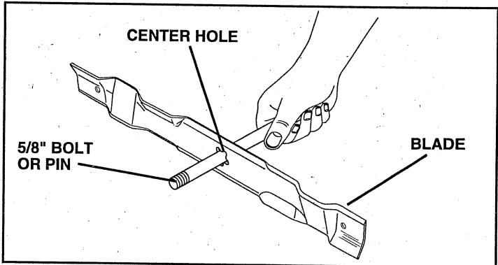
FIG. 14
BATTERY
Your tractor has a battery charging system which is sufficient for normal use. However, periodic charging of the battery with an automotive charger will extend its life.
- Keep battery and terminals clean.
- Keep battery bolts tight.
- Keep small vent holes open.
- Recharge at 6-10 amperes for 1 hour.
TO CLEAN BATTERY AND TERMINALS
Corrosion and dirt on the battery and terminals can cause the battery to "leak" power.
- Open battery box door.
- Disconnect BLACK battery cable first then RED battery cable and remove battery from tractor.
- Rinse the battery with plain water and dry.
- Clean terminals and battery cable ends with wire brush until bright.
- Coat terminals with grease or petroleum jelly.
- Reinstall battery (See "CONNECT BATTERY" in the Assembly section of this manual).
V-BELTS
Check V-belts for deterioration and wear after 100 hours of operation and replace if necessary. The belts are not adjustable. Replace belts if they begin to slip from wear.
CUSTOMER RESPONSIBILITIES
TRANSAXLE COOLING
The fan and cooling fins of transmission should be kept clean to assure proper cooling.
Do not attempt to clean fan or transmission while engine is running or while the transmission is hot.
- Inspect cooling fan to be sure fan blades are intact and clean.
- Inspect cooling fins for dirt, grass clippings and other materials. To prevent damage to seals, do not use compressed air or high pressure sprayer to clean cooling fins.
TRANSAXLE PUMP FLUID
The transaxle was sealed at the factory and fluid maintenance is not required for the life of the transaxle. Should the transaxle ever leak or require servicing, contact your nearest authorized service center/department.
ENGINE
LUBRICATION
Only use high quality detergent oil rated with API service classification SF or SG. Select the oil's SAE viscosity grade according to your expected operating temperature.
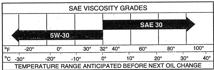
NOTE: Although multi-viscosity oils (5W30, 10W30 etc.) improve starting in cold weather, these multi-viscosity oils will result in increased oil consumption when used above 32^ . Check your engine oil level more frequently to avoid possible engine damage from running low on oil.
- Change the oil after the first two hours of operation and every 25 hours thereafter or at least once a year if the tractor is not used for 25 hours in one year.
Check the crankcase oil level before starting the engine and after each eight (8) hours of operation. Tighten oil fill cap/dipstick securely each time you check the oil level.
TO CHANGE ENGINE OIL (See Fig. 15)
Determine temperature range expected before oil change. All oil must meet API service classification SF or SG.
- Be sure tractor is on level surface.
Oil will drain more freely when warm.
Catch oil in a suitable container. - Remove oil fill cap/dipstick. Be careful not to allow dirt to enter the engine when changing oil.
-
Remove drain plug.
After oil has drained completely, replace oil drain plug and tighten securely. -
Refill engine with oil through oil fill dipstick tube. Pour slowly. Do not overfill. For approximate capacity see "PRODUCT SPECIFICATIONS" on page 3 of this manual.
- Use gauge on oil fill cap/dipstick for checking level. Be sure dipstick cap is tightened securely for accurate reading. Keep oil at "FULL" line on dipstick.
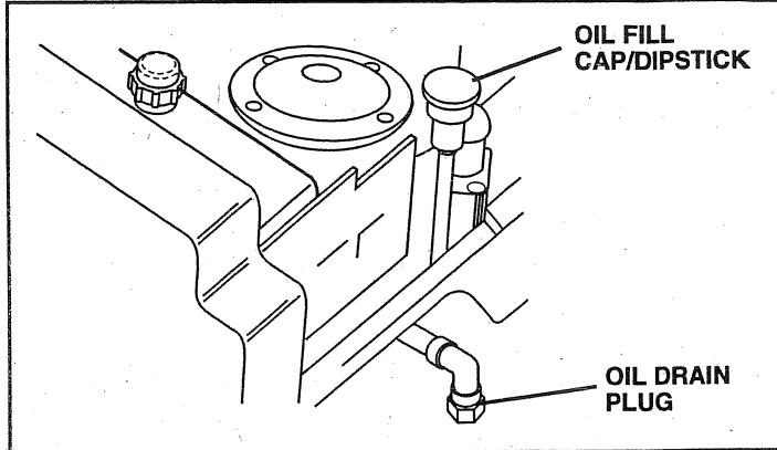
FIG. 15
AIR FILTER (See Fig. 16)
Your engine will not run properly using a dirty air filter. Clean the foam pre-cleaner after every 25 hours of operation or every season. Service paper cartridge every 100 hours of operation or every season, whichever occurs first. Service air cleaner more often under dusty conditions.
- Remove knob(s) and cover.
TO SERVICE PRE-CLEANER
- Slide foam pre-cleaner off cartridge.
- Wash it in liquid detergent and water.
- Squeeze it dry in a clean cloth.
- Saturate it in engine oil. Wrap it in clean, absorbent cloth and squeeze to remove excess oil.
If very dirty or damaged, replace pre-cleaner. - Reinstall pre-cleaner over cartridge.
- Reinstall cover and secure with knob(s).
TO SERVICE CARTRIDGE
- Remove cartridge nut.
- Carefully remove cartridge to prevent debris from entering carburetor. Clean base carefully to prevent debris from entering carburetor.
- Clean cartridge by tapping gently on flat surface. If very dirty or damaged, replace cartridge.
- Reinstall cartridge, nut, precleaner, cover and secure with knob(s).
IMPORTANT: PETROLEUM SOLVENTS, SUCH AS KEROSENE, ARE NOT TO BE USED TO CLEAN THE CARTRIDGE. THEY MAY CAUSE DETERIORATION OF THE CARTRIDGE. DO NOT OIL CARTRIDGE. DO NOT USE PRESSURIZED AIR TO CLEAN OR DRY CARTRIDGE.
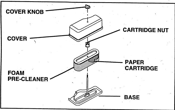
FIG. 16
CLEAN AIR SCREEN (See Fig. 17)
Air screen must be kept free of dirt and chaff to prevent engine damage from overheating. Clean with a wire brush or compressed air to remove dirt and stubborn dried gum fibers.
ENGINE COOLING FINS (See Fig. 17)
Remove any dust, dirt or oil from engine cooling fins to prevent engine damage from overheating.
- Remove screws from blower housing and lift housing and dipstick tube assembly off engine.
Cover oil fill opening to prevent entry of dirt. - Use compressed air or stiff bristle brush to thoroughly clean engine cooling fins.
To reassemble, reverse above procedure.
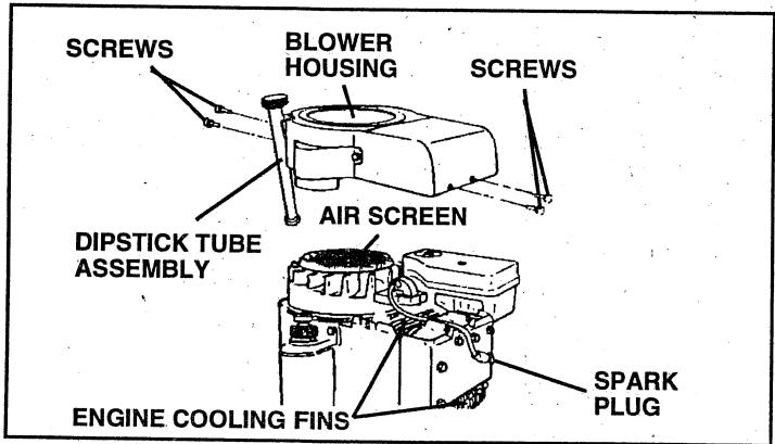
FIG. 17
MUFFLER
Inspect and replace corroded muffler and spark arrester (if equipped) as it could create a fire hazard and/or damage.
SPARK PLUGS
Replace spark plugs at the beginning of each mowing season or after every 100 hours of operation, whichever occurs first. Spark plug type and gap setting are shown in "PRODUCT SPECIFICATIONS" on page 3 of this manual.
IN-LINE FUEL FILTER (See Fig. 18)
The fuel filter should be replaced once each season. If fuel filter becomes clogged, obstructing fuel flow to carburetor, replacement is required.
- With engine cool, remove filter and plug fuel line sections.
- Place new fuel filter in position in fuel line with arrow pointing towards carburetor.
- Be sure there are no fuel line leaks and clamps are properly positioned.
- Immediately wipe up any spilled gasoline.
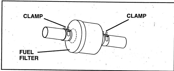
FIG. 18
CLEANING
- Clean engine, battery, seat, finish, etc. of all foreign matter.
- Keep finished surfaces and wheels free of all gasoline, oil, etc.
- Protect painted surfaces with automotive type wax.
We do not recommend using a garden hose to clean your tractor unless the electrical system, muffler, air filter and carburetor are covered to keep water out. Water in engine can result in a shortened engine life.

CAUTION: BEFORE PERFORMING ANY SERVICE OR ADJUSTMENTS:
- Depress clutch/brake pedal fully and set parking brake.
- Place motion control lever in neutral (N) position.
- Place attachment clutch in "DISENGAGED" position.
- Turn ignition key "OFF" and remove key.
- Make sure the blades and all moving parts have completely stopped.
- Disconnect spark plug wire from spark plug and place wire where it cannot come in contact with plug.
TRACTOR
TO REMOVE MOWER (See Fig. 19)
Mower will be easier to remove from the right side of tractor.
- Place attachment clutch in "DISENGAGED" position.
- Move attachment lift lever forward to lower mower to its lowest position.
Roll belt off engine pulley. - Disconnect clutch rod from clutch lever by removing retainer spring.
- Disconnect anti-sway bar from chassis bracket by removing retainer spring.
- Disconnect suspension arms from rear deck brackets by removing retainer springs.
- Disconnect front links from deck by removing retainer springs.
- Raise lift lever to raise suspension arms. Slide mower out from under tractor.
IMPORTANT: IF AN ATTACHMENT OTHER THAN THE MOWER IS TO BE MOUNTED TO THE TRACTOR, THE R.H. AND L.H. SUSPENSION ARMS MUST BE REMOVED FROM TRACTOR.
TO INSTALL MOWER (See Fig. 19)
- Raise attachment lift lever to its highest position.
- Slide mower under tractor with discharge guard to right side of tractor.
Lower lift lever to its lowest position.
Install mower in reverse order of removal instructions.
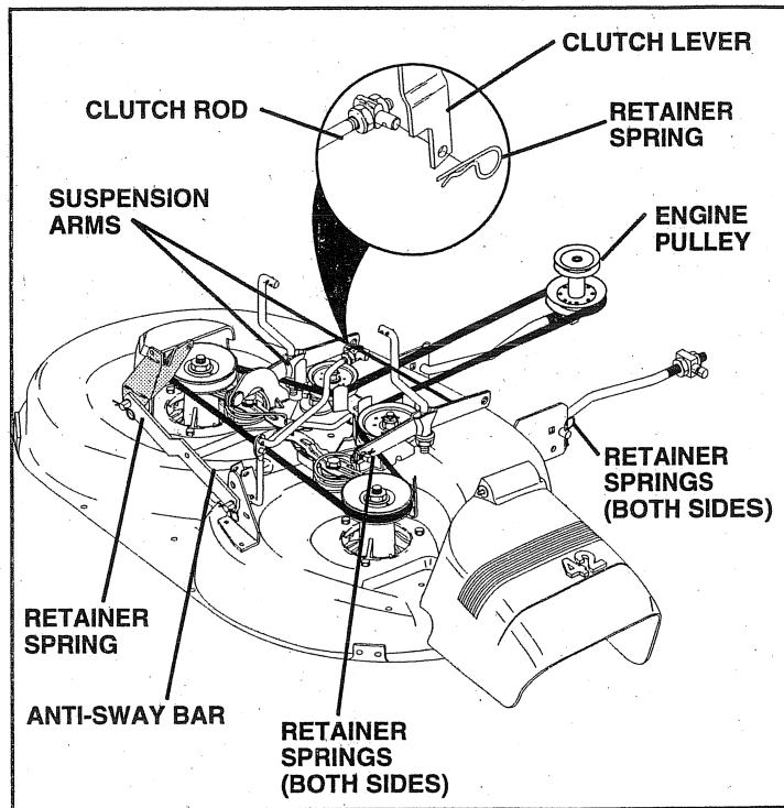
FIG. 19
TO LEVEL MOWER HOUSING
Adjust the mower while tractor is parked on level ground or driveway. Make sure tires are properly inflated (See "PRODUCT SPECIFICATIONS" on page 3 of this manual). If tires are over or underinflated, you will not properly adjust your mower.
SIDE-TO-SIDE ADJUSTMENT (See Figs. 20 and 21)
- Raise mower to its highest position.
- At the midpoint of both sides of mower, measure height from bottom edge of mower to ground. Distance "A" on both sides of mower should be the same or within 1/4 of each other.
- If adjustment is necessary, make adjustment on one side of mower only.
- To raise one side of mower, tighten lift link adjustment nut on that side.
- To lower one side of mower, loosen lift link adjustment nut on that side.
NOTE: Three full turns of adjustment nut will change mower height about 1/8" .
- Recheck measurements after adjusting.
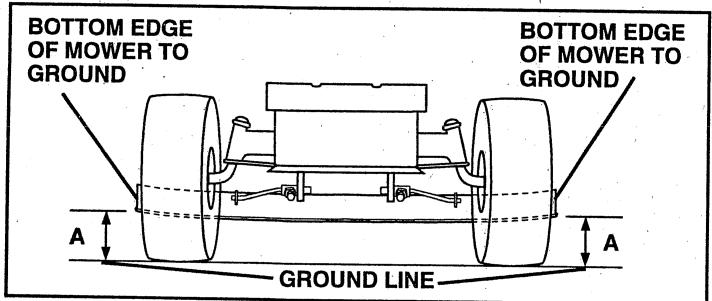
FIG. 20
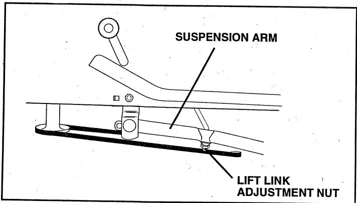
FIG. 21
FRONT-TO-BACK ADJUSTMENT (See Figs. 22 and 23)
IMPORTANT: DECK MUST BE LEVEL SIDE-TO-SIDE. IF THE FOLLOWING FRONT-TO-BACK ADJUSTMENT IS NECESSARY, BE SURE TO ADJUST BOTH FRONT LINKS EQUALLY SO MOWER WILL STAY LEVEL SIDE-TO-SIDE.
To obtain the best cutting results, the mower housing should be adjusted so that the front is approximately 1/4'' to 3/4'' lower than the rear when the mower is in its highest position.
Check adjustment on right side of tractor. Measure distance "D" directly in front and behind the mandrel at bottom edge of mower housing as shown.
- Before making any necessary adjustments, check that both front links are equal in length. Both links should be approximately 10-3/8".
- If links are not equal in length, adjust one link to same length as other link.
- To lower front of mower loosen nut "E" on both front links an equal number of turns.
- When distance "D" is 14 to 34 lower at front than rear, tighten nuts "F" against trunnion on both front links.
- To raise front of mower, loosen nut "F" from trunnion on both front links. Tighten nut "E" on both front links an equal number of turns.
- When distance “D” is 1/4 to 3/4 lower at front than rear, tighten nut “F” against trunnion on both front links.
- Recheck side-to-side adjustment.
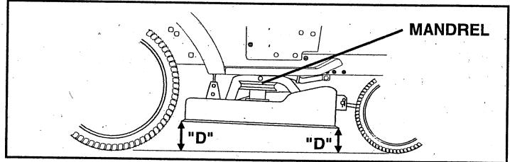
FIG. 22
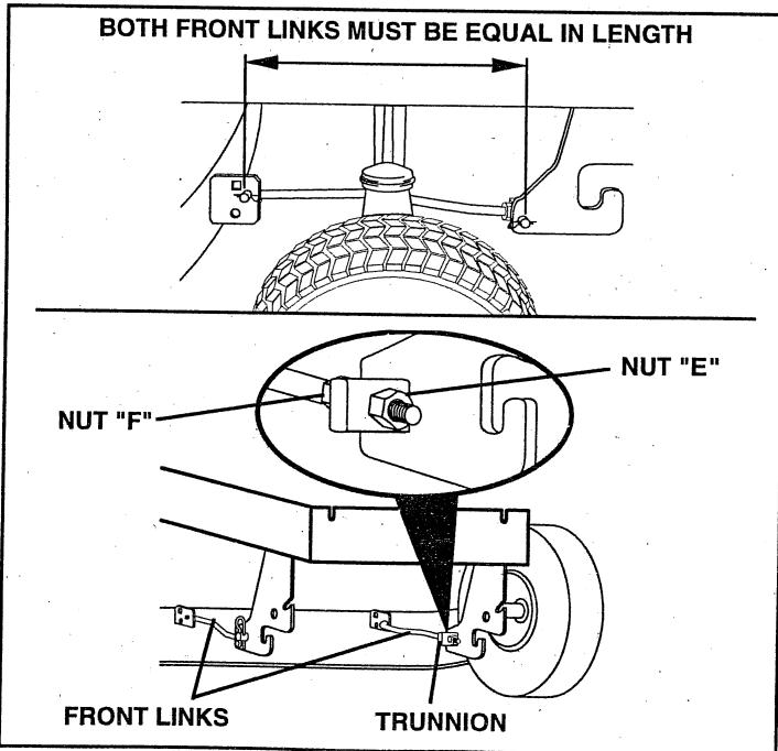
FIG. 23
SERVICE AND ADJUSTMENTS
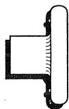
TO REPLACE MOWER BLADE DRIVE BELT (See Fig. 24)
The mower blade drive belt may be replaced without tools. Park the tractor on level surface. Engage parking brake.
BELT REMOVAL -
- Remove mower from tractor (See "TO REMOVE MOWER" in this section of this manual).
Work belt off both mandrel pulleys and idler pulleys.
Pull belt away from mower.
BELT INSTALLATION -
Install new belt in reverse order of removal.
- Make sure belt is in all pulley grooves and inside all belt guides.
Install mower in reverse order of removal instructions.
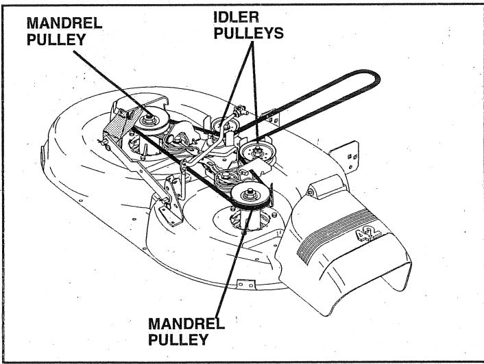
FIG. 24
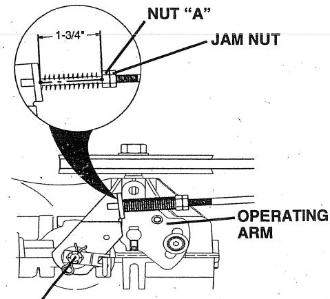
TO ADJUST BRAKE (See Fig. 25)
Your tractor is equipped with an adjustable brake system, which is mounted on the side of the transaxle.
If tractor requires more than six (6) feet stopping distance at high speed in highest gear, then brake must be adjusted.
- Depress clutch/brake pedal and engage parking brake.
Measure distance between brake operating arm and nut "A" on brake rod. - If distance is other than 1 - 3 / 4 , loosen jam nut and turn nut "A" until distance becomes 1 - 3 / 4 . Retighten jam nut against nut "A".
- Road test tractor for proper stopping distance as stated above. Readjust if necessary. If stopping distance is still greater than six (6) feet in highest gear, further maintenance is necessary. Contact your nearest authorized service center/department.
WITH PARKING BRAKE "ENGAGED"
FIG. 25
DO NOT TOUCH THIS NUT. IF FURTHER BRAKE ADJUSTMENT IS NECESSARY CONTACT YOUR NEAREST AUTHORIZED SERVICE CENTER/DEPARTMENT
TO REPLACE MOTION DRIVE BELT (See Fig. 26)
-
Park the tractor on level surface. Engage parking brake. For assistance, there is a belt installation guide decal on bottom side of left footrest.
-
Remove mower (See "TO REMOVE MOWER" in this section of this manual.)
- Remove upper belt keeper.
- Remove belt from stationary idler and clutching idler.
- Pull belt slack toward rear of tractor. Carefully remove belt upwards from transmission input pulley and over cooling fan blades.
Pull belt toward front of tractor and remove downward from around engine pulley.
Install new belt by reversing above procedure.
IMPORTANT: MAKE SURE UPPER BELT KEBPER IS POSITIONED PROPERLY BETWEEN LOCATOR TABS.
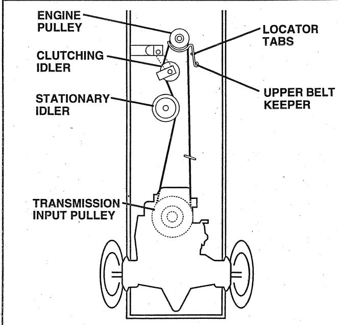
FIG. 26
TO ADJUST MOTION CONTROL LEVER (See Fig. 27)
The motion control lever has been preset at the factory and adjustment should not be necessary.
If for any reason the motion control lever will not hold its position while at a selected speed, it may be adjusted at the friction pack located on the right side of transmission.
- Park tractor on level surface. Stop tractor by turning ignition key to "OFF" position, and engage parking brake.
- Adjust motion control lever by tightening adjustment locknut one half (1/2) turn.
NOTE: If for any reason the effort to move the motion control lever becomes too excessive, reverse the above adjustment procedure by loosening locknut 1/4 to 1/2 turn.
Road test tractor after adjustment and repeat procedure if necessary.
TRANSMISSION REMOVAL/REPLACEMENT
Should your transmission require removal for service or replacement, it should be purged after reinstallation and before operating the tractor. See "PURGE TRANSMISSION" in the Operation section of this manual.
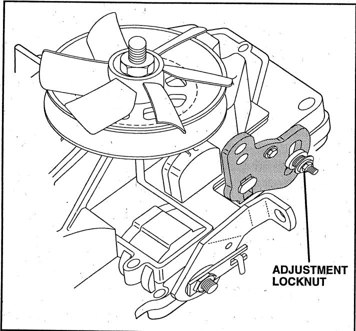
FIG. 27
TO ADJUST STEERING WHEEL ALIGNMENT
If steering wheel crossbars are not horizontal (left to right) when wheels are positioned straight forward, remove steering wheel and reassemble per instructions in the Assembly section of this manual.
FRONT WHEEL TOE-IN/CAMBER
The front wheel toe-in and camber are not adjustable on your tractor. If damage has occurred to affect the front wheel toe-in or camber, contact your nearest authorized service center/department.
TO REMOVE WHEEL FOR REPAIRS (See Fig. 28)
- Block up axle securely.
- Remove axle cover, retaining ring and washers to allow wheel removal (rear wheel contains a square key - Do not lose).
Repair tire and reassemble. - On rear wheels only: align grooves in rear wheel hub and axle. Insert square key.
- Replace washers and snap retaining ring securely in axle groove.
- Replace axle cover.
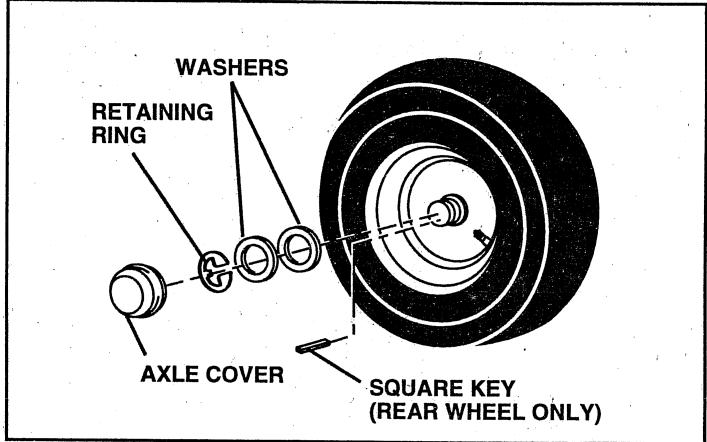
FIG. 28
TO START ENGINE WITH A WEAK BATTERY (See Fig. 29)

CAUTION: Lead-acid batteries generate explosive gases. Keep sparks, flame and smoking materials away from batteries. Always wear eye protection when around batteries.
If your battery is too weak to start the engine, it should be recharged. If "jumper cables" are used for emergency starting, follow this procedure:
IMPORTANT: YOUR TRACTOR IS EQUIPPED WITH A 12 VOLT NEGATIVE GROUNDED SYSTEM. THE OTHER VEHICLE MUST ALSO BE A 12 VOLT NEGATIVE GROUNDED SYSTEM. DO NOT USE YOUR TRACTOR BATTERY TO START OTHER VEHICLES.
TO ATTACH JUMPER CABLES -
- Connect each end of the RED cable to the POSITIVE (+) terminal of each battery, taking care not to short against chassis.
- Connect one end of the BLACK cable to the NEGATIVE (-) terminal of fully charged battery.
- Connect the other end of the BLACK cable to good CHASSIS GROUND, away from fuel tank and battery.
TO REMOVE CABLES, REVERSE ORDER -
- BLACK cable first from chassis and then from the fully charged battery.
- RED cable last from both batteries.
SERVICE AND ADJUSTMENTS
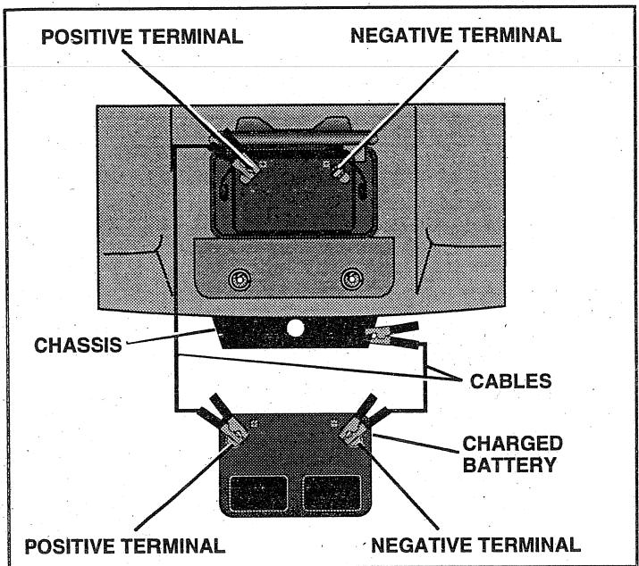
FIG. 29
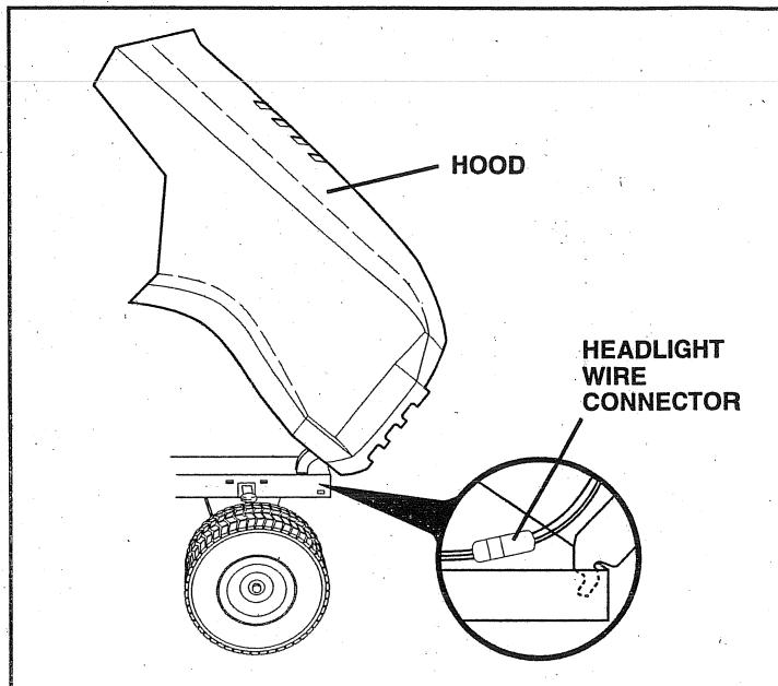
FIG. 30
TO REPLACE HEADLIGHT BULB
- Raise hood.
Pull bulb holder out of the hole in the backside of the grill. - Replace bulb in holder and push bulb holder securely back into the hole in the backside of the grill.
- Close hood.
INTERLOCKS AND RELAYS
Loose or damaged wiring may cause your tractor to run poorly, stop running, or prevent it from starting.
- Check wiring. See electrical wiring diagram in the Repair Parts section of this manual.
TO REPLACE FUSE
Replace with 30 amp automotive-type plug-in fuse. The fuse holder is located behind the dash.
TO REMOVE HOOD AND GRILL ASSEMBLY (See Fig. 30)
- Raise hood.
Unsnap headlight wire connector. - Stand in front of tractor. Grasp hood at sides, tilt toward engine and lift off of tractor.
To replace, reverse above procedures.
ENGINE
TO ADJUST THROTTLE CONTROL CABLE (See Fig. 31)
The throttle control has been preset at the factory and adjustment should not be necessary. Check adjustment as described below before loosening cable. If adjustment is necessary, proceed as follows:
- With engine not running, move throttle control lever from slow (一) to choke () position. Slowly move lever from choke () to fast (一) position.
- Check that holes "A" in governor control lever and hole in governor plate line-up. If holes "A" are not aligned, loosen clamp screw and move throttle cable until holes are aligned. Tighten clamp screw securely.
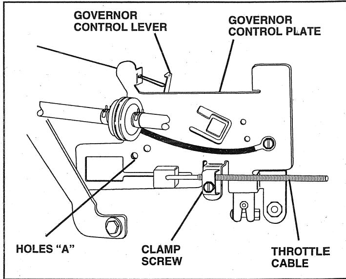
FIG. 31
SERVICE AND ADJUSTMENTS
TO ADJUST CARBURETOR (See Fig. 32)
The carburetor has been preset at the factory and adjustment should not be necessary. However, minor adjustment may be required to compensate for differences in fuel, temperature, altitude or load. If the carburetor does need adjustment, proceed as follows:
In general, turning idle mixture valve in (clockwise) decreases the supply of fuel to the engine giving a leaner fuel/air mixture. Turning the idle mixture valve out (counterclockwise) increases the supply of fuel to the engine giving a richer fuel/air mixture.
IMPORTANT: DAMAGE TO THE NEEDLE VALVE AND THE SEAT IN CARBURETOR MAY RESULT IF SCREW IS TURNED IN TOO TIGHT.
PRELIMINARY SETTING -
Air cleaner assembly must be assembled to the carburetor when making carburetor adjustments.
- Be sure the throttle control cable is adjusted properly (see above).
- With engine off turn idle mixture valve in (clockwise) closing it finger tight and then turn out (counterclockwise) 1 full turn.
FINAL SETTING -
- Start engine and allow to warm for five minutes. Make final adjustments with engine running and shift/motion control lever in neutral (N) position.
- Move throttle control lever to slow. () position. With finger, rotate and hold throttle lever against idle speed screw. Turn idle speed screw to attain 1750 RPM.
While still holding throttle lever against idle speed screw, turn idle mixture valve in (clockwise) until engine begins to die and then turn out (counterclockwise) until engine runs rough. Turn valve to a point midway between those two positions. Release throttle lever.
ACCELERATION TEST -
- Move throttle control lever from slow (→) to fast (←) position. If engine hesitates or dies, turn idle mixture valve out (counterclockwise) 1/8 turn. Repeat test and continue to adjust, if necessary, until engine accelerates smoothly.
High speed stop is factory adjusted. Do not adjust - damage may result.
IMPORTANT: NEVER TAMPER WITH THE ENGINE GOVERNOR, WHICH IS FACTORY SET FOR PROPER ENGINE SPEED. OVERSPEEDING THE ENGINE ABOVE THE FACTORY HIGH SPEED SETTING CAN BE DANGEROUS. IF YOU THINK THE ENGINE-GOVERNED HIGH SPEED NEEDS ADJUSTING, CONTACT YOUR NEAREST AUTHORIZED SERVICE CENTER/ DEPARTMENT, WHICH HAS PROPER EQUIPMENT AND EXPERIENCE TO MAKE ANY NECESSARY ADJUSTMENTS.
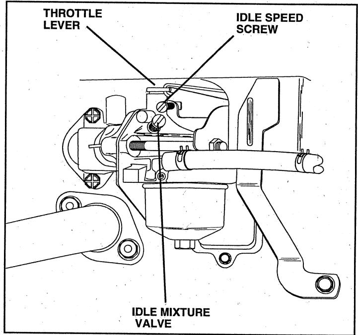
FIG. 32
STORAGE
Immediately prepare your tractor for storage at the end of the season or if the tractor will not be used for 30 days or more.

CAUTION: Never store the tractor with gasoline in the tank inside a building where fumes may reach an open flame or spark. Allow the engine to cool before storing in any enclosure.
TRACTOR
Remove mower from tractor for winter storage. When mower is to be stored for a period of time, clean it thoroughly, remove all dirt, grease, leaves, etc. Store in a clean, dry area.
- Clean entire tractor (See "CLEANING" in the Customer Responsibilities section of this manual).
- Inspect and replace belts, if necessary (See belt replacement instructions in the Service and Adjustments section of this manual).
- Lubricate as shown in the Customer Responsibilities section of this manual.
- Be sure that all nuts, bolts and screws are securely fastened. Inspect moving parts for damage, breakage and wear. Replace if necessary.
- Touch up all rusted or chipped paint surfaces; sand lightly before painting.
BATTERY
- Fully charge the battery for storage.
After a period of time in storage, battery may require recharging. - To help prevent corrosion and power leakage during long periods of storage, battery cables should be disconnected and battery cleaned thoroughly (see "TO CLEAN BATTERY AND TERMINALS" in the Customer Responsibilities section of this manual).
After cleaning, leave cables disconnected and place cables where they cannot come in contact with battery terminals. - Be sure battery drain tube is securely attached.
If battery is removed from tractor for storage, do not store battery directly on concrete or damp surfaces.
ENGINE
FUEL SYSTEM
IMPORTANT: IT IS IMPORTANT TO PREVENT GUM DEPOSITS FROM FORMING IN ESSENTIAL FUELS. SYSTEM PARTS SUCH AS CARBURETOR, FUEL FILTER, FUEL HOSE, OR TANK DURING STORAGE. ALSO, EXPERIENCE INDICATES THAT ALCOHOL BLENDED FUELS (CALLLED GASOHOL OR USING ETHANOL OR METHANOL) CAN ATTRACT MOISTURE WHICH LEADS TO SEPARATION AND FORMATION OF ACIDS DURING STORAGE. ACIDIC GAS CAN DAMAGE THE FUELS. SYSTEM OF AN ENGINE WHILE IN STORAGE.
- Drain the fuel tank.
- Start the engine and let it run until the fuel lines and carburetor are empty.
- Never use engine or carburetor cleaner products in the fuel tank or permanent damage may occur.
Use fresh fuel next season.
NOTE: Fuel stabilizer is an acceptable alternative in minimizing the formation of fuel gum deposits during storage. Add stabilizer to gasoline in fuel tank or storage container. Always follow the mix ratio found on stabilizer container. Run engine at least 10 minutes after adding stabilizer to allow the stabilizer to reach the carburetor. Do not drain the gas tank and carburetor if using fuel stabilizer.
ENGINE OIL
- Drain oil (with engine warm) and replace with clean engine oil. (See "ENGINE" in the Customer Responsibilities section of this manual).
CYLINDERS
- Remove spark plug(s).
- Pour one ounce of oil through spark plug hole(s) into cylinder(s).
- Turn ignition key to "START" position for a few seconds to distribute oil.
- Replace with new spark plug(s).
OTHER
- Do not store gasoline from one season to another.
- Replace your gasoline can if your can starts to rust. Rust and/or dirt in your gasoline will cause problems
- If possible, store your tractor indoors and cover it to give protection from dust and dirt.
- Cover your tractor with a suitable protective cover that does not retain moisture. Do not use plastic. Plastic cannot breathe which allows condensation to form and will cause your tractor to rust.
IMPORTANT: NEVER COVER TRACTOR WHILE ENGINE AND EXHAUST ARE ARE STILL WARM.
TROUBLESHOOTING POINTS
| PROBLEM | CAUSE | CORRECTION |
| Will not start | 1. Out of fuel. 2. Engine not "CHOKED" properly. 3. Engine flooded. 4. Bad spark plug. 5. Dirty air filter. 6. Dirty fuel filter. 7. Water in fuel. 8. Loose or damaged wiring. 9. Carburetor out of adjustment. 10. Engine valves out of adjustment. | 1. Fill fuel tank. 2. See "TO START ENGINE" in Operation section. 3. Wait several minutes before attempting to start. 4. Replace spark plug. 5. Clean/replace air filter. 6. Replace fuel filter. 7. Drain fuel tank and carburetor, refill tank with fresh gasoline and replace fuel filter. 8. Check all wiring. 9. Contact an authorized service center/department. 10. Contact an authorized service center/department. |
| Hard to start | 1. Dirty air filter. 2. Bad spark plug. 3. Weak or dead battery. 4. Dirty fuel filter. 5. Stale or dirty fuel. 6. Loose or damaged wiring. 7. Carburetor out of adjustment. 8. Engine valves out of adjustment. | 1. Clean/replace air filter. 2. Replace spark plug. 3. Recharge or replace battery. 4. Replace fuel filter. 5. Drain fuel tank and refill with fresh gasoline. 6. Check all wiring. 7. Contact an authorized service center/department. 8. Contact an authorized service center/department. |
| Engine will not turn over | 1. Clutch/brake pedal not depressed. 2. Attachment clutch is engaged. 3. Weak or dead battery. 4. Blown fuse. 5. Corroded battery terminals. 6. Loose or damaged wiring. 7. Faulty ignition switch. 8. Faulty solenoid or starter. 9. Faulty operator presence switch(es). | 1. Depress clutch/brake pedal. 2. Disengage attachment clutch. 3. Recharge or replace battery. 4. Replace fuse. 5. Clean battery terminals. 6. Check all wiring. 7. Check/replace ignition switch. 8. Check/replace solenoid or starter. 9. Contact an authorized service center/department. |
| Engine clicks but will not start | 1. Weak or dead battery. 2. Corroded battery terminals. 3. Loose or damaged wiring. 4. Faulty solenoid or starter. | 1. Recharge or replace battery. 2. Clean battery terminals. 3. Check all wiring. 4. Check/replace solenoid or starter. |
| Loss of power | 1. Cutting too much grass/too fast. 2. Throttle in "CHoke" position. 3. Build-up of grass, leaves and trash under mower. 4. Dirty air filter. 5. Low oil level/dirty oil. 6. Faulty spark plug. 7. Dirty fuel filter. 8. Stale or dirty fuel. 9. Water in fuel. 10. Spark plug wire loose. 11. Dirty engine air screen/fins. 12. Dirty/clogged muffler. 13. Loose or damaged wiring. 14. Carburetor out of adjustment. 15. Engine valves out of adjustment. | 1. Set in "Higher Cut" position/reduce speed. 2. Adjust throttle control. 3. Clean underside of mower housing. 4. Clean/replace air filter. 5. Check oil level/change oil. 6. Clean and regap or change spark plug. 7. Replace fuel filter. 8. Drain fuel tank and refill with fresh gasoline. 9. Drain fuel tank and carburetor, refill tank with fresh gasoline and replace fuel filter. 10. Connect and tighten spark plug wire. 11. Clean engine air screen/fins. 12. Clean/replace muffler. 13. Check all wiring. 14. Contact an authorized service center/department. 15. Contact an authorized service center/department. |
| Excessive vibration | 1. Worn, bent or loose blade. 2. Bent blade mandrel. 3. Loose/damaged part(s). | 1. Replace blade. Tighten blade bolt. 2. Replace blade mandrel. 3. Tighten loose part(s). Replace damaged parts. |
TROUBLESHOOTING POINTS
| PROBLEM | CAUSE | CORRECTION |
| Engine continues to run when operator leaves seat with attachment clutch engaged | 1. Faulty operator-safety presence control system. | 1. Check wiring, switches and connections. If not corrected, contact an authorized service center/department. |
| Poor cut - uneven | 1. Worn, bent or loose blade. 2. Mower deck not level. 3. Buildup of grass, leaves, and trash under mower. 4. Bent blade mandrel. 5. Clogged mower deck vent holes from buildup of grass, leaves, and trash around mandrels. | 1. Replace blade. Tighten blade bolt. 2. Level mower deck. 3. Clean underside of mower housing. 4. Replace blade mandrel. 5. Clean around mandrels to open vent holes. |
| Mower blades will not rotate | 1. Obstruction in clutch mechanism. 2. Worn/damaged mower drive belt. 3. Frozen idler pulley. 4. Frozen blade mandrel. | 1. Remove obstruction. 2. Replace mower drive belt. 3. Replace idler pulley. 4. Replace blade mandrel. |
| Poor grass discharge | 1. Engine speed too slow. 2. Travel speed too fast. 3. Wet grass. 4. Mower deck not level. 5. Low/uneven tire air pressure. 6. Worn, bent or loose blade. 7. Buildup of grass, leaves and trash under mower. 8. Mower drive belt worn. 9. Blades improperly installed. 10. Improper blades used. 11. Clogged mower deck vent holes from buildup of grass, leaves, and trash around mandrels. | 1. Place throttle control in "FAST" position. 2. Shift to slower speed. 3. Allow grass to dry before mowing. 4. Level mower deck. 5. Check tires for proper air pressure. 6. Replace/sharpen blade. Tighten blade bolt. 7. Clean underside of mower housing. 8. Replace mower drive belt. 9. Reinstall blades sharp edge down. 10. Replace with blades listed in this manual. 11. Clean around mandrels to open vent holes. |
| Headlight(s) not working (if so equipped) | 1. Switch is "OFF". 2. Bulb(s) burned out. 3. Faulty light switch. 4. Loose or damaged wiring. 5. Blown fuse. | 1. Turn switch "ON". 2. Replace bulb(s). 3. Check/replace light switch. 4. Check wiring and connections. 5. Replace fuse. |
| Battery will not charge | 1. Bad battery cell(s). 2. Poor cable connections. 3. Faulty regulator (if so equipped). 4. Faulty alternator. | 1. Replace battery. 2. Check/clean all connections. 3. Replace regulator. 4. Replace alternator. |
| Engine "backfires" when turning engine "OFF" | 1. Engine throttle control not set at "SLOW" position for 30 seconds before stopping engine. | 1. Move throttle control to "SLOW" position and allow to idle for 30 seconds before stopping engine. |
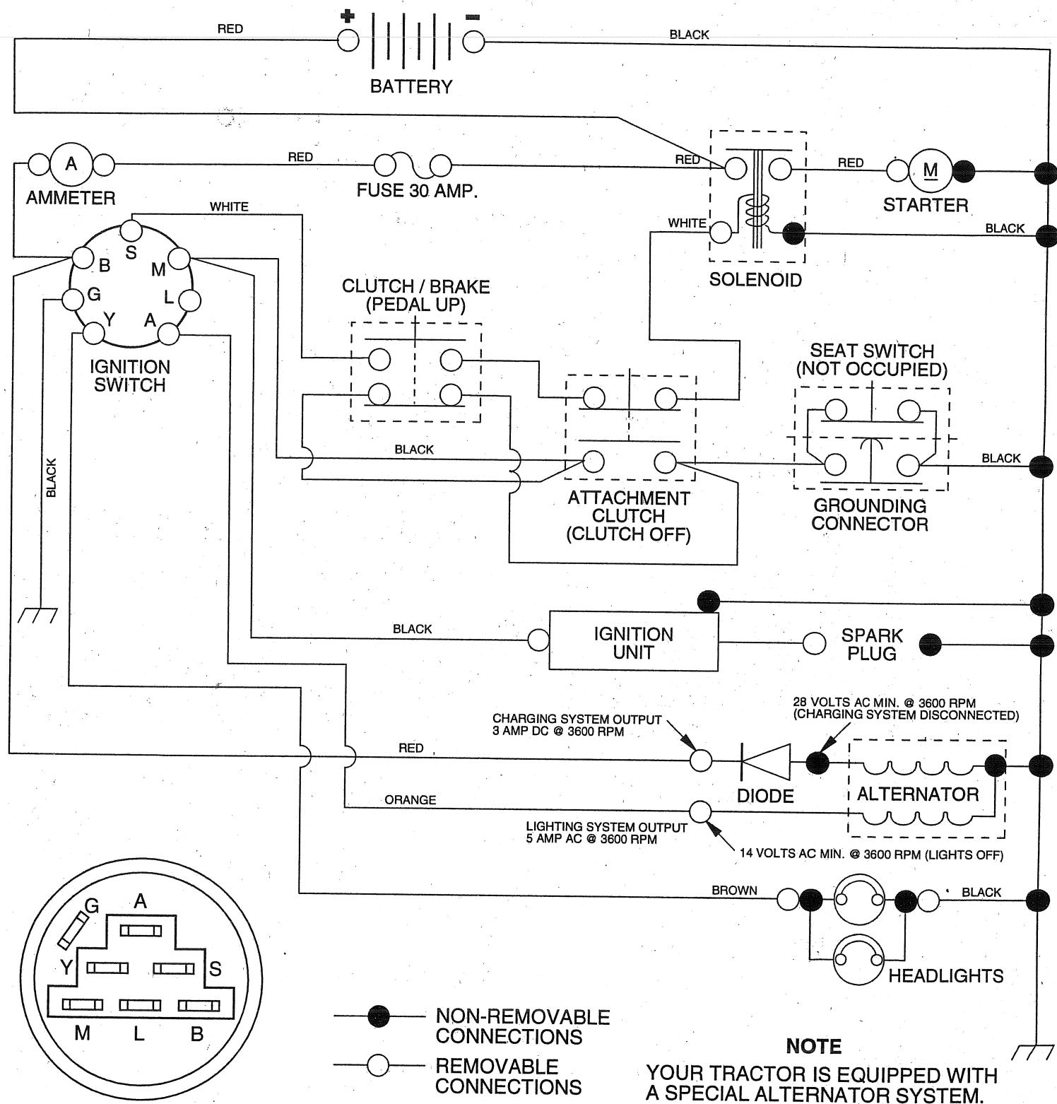
TRACTOR- -MODEL NO. LTH130 (HCLTH130A), PRODUCT NO. 954 88 00-61 SCHEMATIC
IGNITION SWITCH
| POSITION | CIRCUIT | "MAKE" |
| OFF | G + M + L | NONE |
| RUN/LIGHT | B + L | A + Y |
| RUN | B + L | NONE |
| START | B + L + S | NONE |
WIRING INSULATED CLIPS
NOTE: IF WIRING INSULATED CLIPS WERE REMOVED FOR SERVICING OF UNIT, THEY SHOULD BE REPLACED TO PROPERLY SECURE YOUR WIRING
YOUR TRACTOR IS EQUIPPED WITH A SPECIAL ALTERNATOR SYSTEM. THE LIGHTS ARE NOT CONNECTED TO THE BATTERY, BUT HAVE THEIR OWN ELECTRICAL SOURCE. BECAUSE OF THIS, THE BRIGHTNESS OF THE LIGHTS WILL CHANGE WITH ENGINE SPEED. AT IDLE THE LIGHTS WILL DIM. AS THE ENGINE IS SPEEDED UP, THE LIGHTS WILL BECOME THEIR BRIGHTEST.
REPAIR PARTS
TRACTOR- -MODEL NO. LTH130 (HCLTH130A), PRODUCT NO. 954 88 00-61 ELECTRICAL
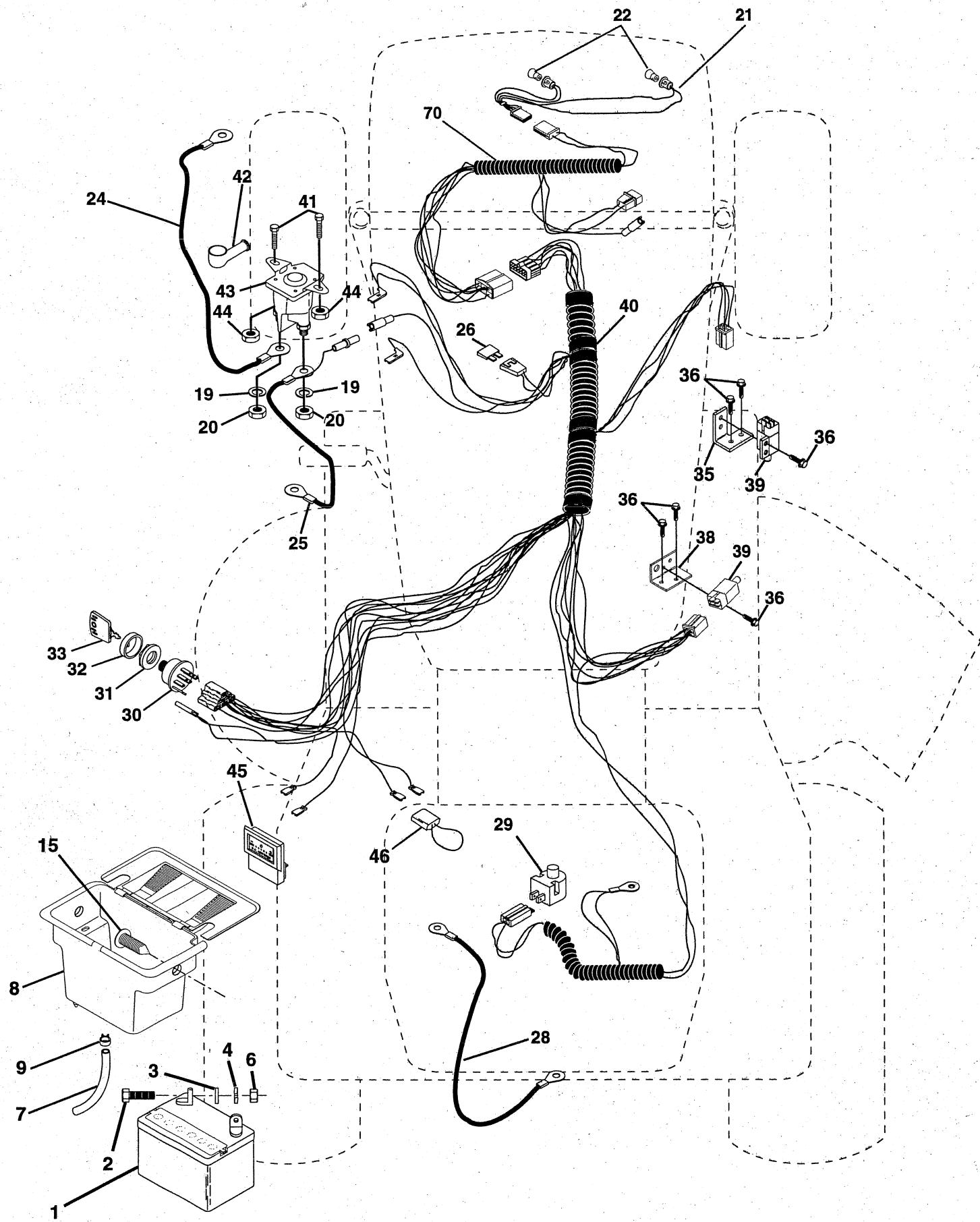
TRACTOR- -MODEL NO. LTH130 (HCLTH130A), PRODUCT NO. 954 88 00-61 ELECTRICAL
KEY PART DESCRIPTION
NO. NO.
1 532144925 Battery 12 Volt 25 Amp
2 874760412 Bolt Hex Hd 1/4-20unc X 3/4
3 819091016 Washer 9/32 X 5/8 X 16 Ga
4 810040400 Washer Lock Hvy Helical 1/4
6 873220400 Nut Fin Hex 1/4-20 Unc
7 532109238 Tube Plastic 20"
8 532144940 Battery Case w/2 Holes W Brty
9 532109596 Clamp Hose Olive
15 532147688 Fastener Snap-In
19 810090400 Washer Lock 1/4
20 873350400 Nut Jam Hex 1/4-20 Unc
21 532147430 Harness Asm Light W/4152j
22 532004152 Bulb Light #1156
24 532124780 Cable Battery 6 Ga 11"red
25 532146147 Cable, Battery 6 Ga Red 44" w/16 W
26 532108824 Fuse 30 AMP Auto Green
28 532124773 Cable Ground 6 Ga 12"black
29 532121305 Switch Plunger Nc Gray
30 532140301 Switch Ign 4 Pos.
31 532124211 Nut Ignition
32 532141226 Cover Sw Key Blk 1 25 Text SLT
33 532122147 Key Ign
35 532108236 Bracket Switch Clutch
36 817021008 Screw Tap Hex #10-24unc X 1/2
38 532140336 Bracket Switch Interlock
39 532109553 Switch Intlk Clutch Gry 4 Term
40 532151212 Harness Ign Lt P/L Mech HM
41 871110408 Bolt Fin Hex 1/4-20 x 1/2
42 532131563 Cover Terminal Red
43 532145673 Solenoid
44 873640400 Nut Keps Hex 1/4-20 Unc
45 532121433 Ammeter Rectangular 6 Amp
46 532141940 Protection Wire Loop (Hourmeter)
70 532141163 Harness Eng. B&S
NOTE: All component dimensions given in U.S. inches.
1 inch = 25.4 mm
REPAIR PARTS
TRACTOR- -MODEL NO. LTH130 (HCLTH130A), PRODUCT NO. 954 88 00-61 CHASSIS AND ENCLOSURES
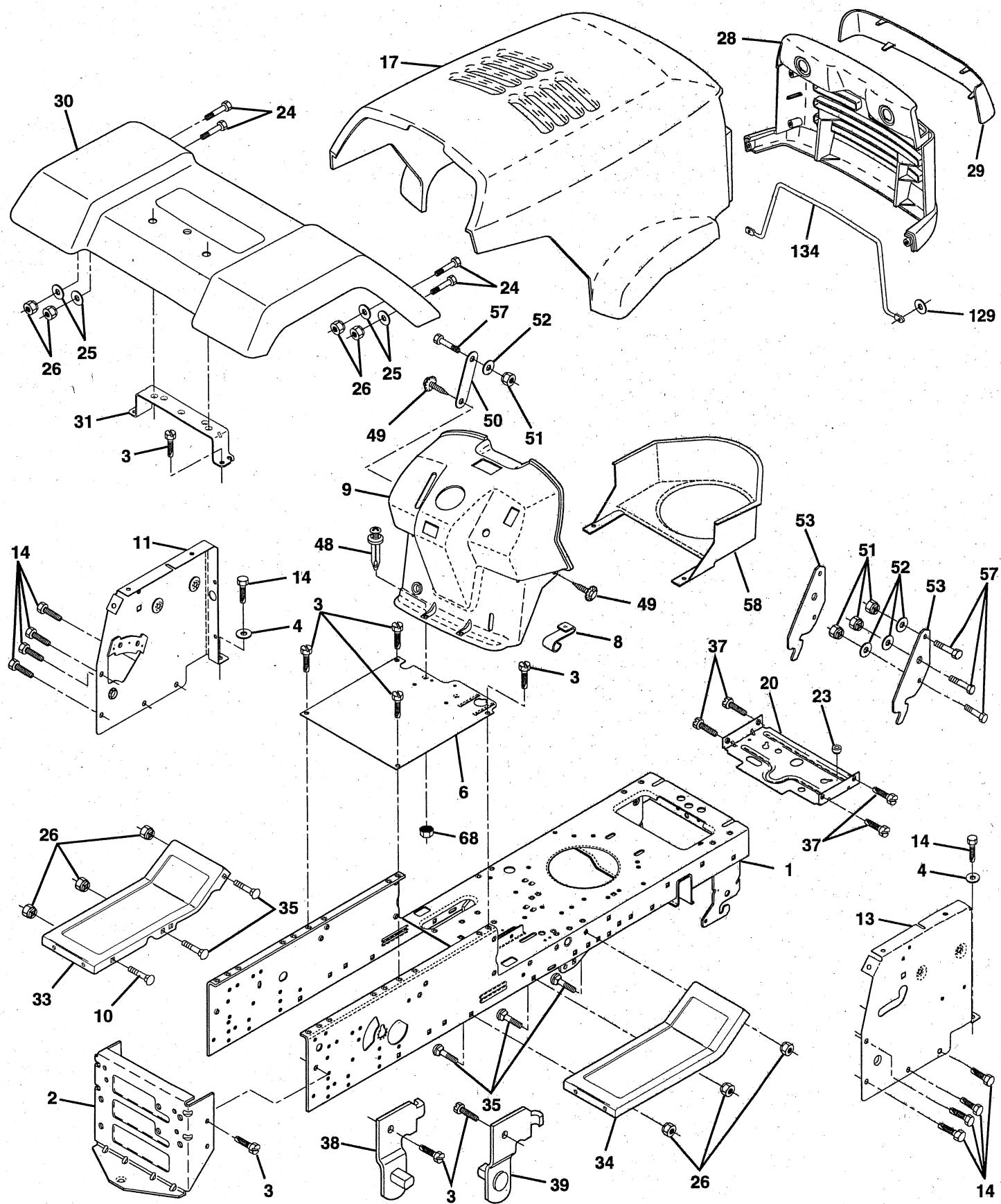
REPAIR PARTS
TRACTOR- -MODEL NO. LTH130 (HCLTH130A), PRODUCT NO. 954 88 00-61 CHASSIS AND ENCLOSURES
KEY PART NO. NO.
DESCRIPTION
| 1 | 532145501 | Chassis Weldment 11ga |
| 2 | 532140356 | Drawbar, Stretch |
| 3 | 817490612 | Screw Thdrol 3/8-16x3/4 Ty- tt |
| 4 | 819131216 | Washer 13/32 x 3/4 x 16 Ga. |
| 6 | 532145206 | Saddle LT Fender Shift |
| 8 | 532126471 | Clip Insulator .406 Mtg Hole |
| 9 | 532151013 | Dash P/L A W/AMM N/HM Grey |
| 10 | 872140608 | Bolt Carriage 3/8-16 x 1 |
| 11 | 532146956 | Panel Pnt Dash Lh |
| 13 | 532146959 | Panel Dash Rh |
| 14 | 817490608 | Screw Thdrol 3/8-16x1/2 Ty- tt |
| 17 | 532149775 | Hood LT/PL Husqvarna |
| 20 | 532145210 | Plate Mtg. Battery Fuel Tank. 95 |
| 23 | 532124028 | Bushing |
| 24 | 874780616 | Bolt Fin Hex 3/8-16unc X 1 Gr. 5 |
| 25 | 819131312 | Washer 13/32 X 13/16 X 12 Ga |
| 26 | 873800600 | Nut Lock Hex W/Ins 3/8-16 Unc |
| 28 | 532149776 | Grille LT/PL Husqvrna |
| 29 | 532149777 | Lens LT/PL Husqvrna |
| 30 | 532143050 | Fender Pnt |
| 31 | 532136619 | Bracket Pnt Fender |
| 33 | 532147203 | Footrest Pnt Lh |
| 34 | 532147202 | Footrest Pnt Rh |
| 35 | 872110606 | Bolt Rdhd Sht Sqnk 3/8-16 X3/4 |
| 37 | 817490508 | Screw Thdrol 5/16-18 X1/2 |
| 38 | 532139886 | Bracket, Asm. Pivot, L.H., Mower Rear |
| 39 | 532139887 | Bracket, Asm. Pivot, R.H., Mower Rear |
| 48 | 532138096 | Rivet Push Plate D Plastick Blk |
| 49 | 817490412 | Screw Hexwsh. Thdrol 1/4-20 x 3/4 |
| 50 | 532142779 | Brace |
| 51 | 873800400 | Nut Lock Hex W/Ins 1/4-20 |
| 52 | 819091416 | Washer 9/32 x 7/8 x 16 Ga. |
| 53 | 532150067 | Bracket Pnt. Pick off LT/PL Husq. |
| 57 | 874780412 | Bolt Hex 1/4-20 x 3/4 |
| 58 | 532150127 | Air Duct Engine P/L |
| 58 | 873510400 | Nut Keps Hex 1/4-20 |
| 59 | 819091016 | Washer 9/32 x 5/8 x 16 Ga. |
| 64 | 532150132 | Rod Support Hood LT/PL Husq. |
| - | 532005479 | Plug Button |
| - | 532134014 | Plug Dome Blk |
NOTE: All component dimensions given in U.S. inches. 1 inch = 25.4 mm
REPAIR PARTS
TRACTOR- -MODEL NO. LTH130 (HCLTH130A), PRODUCT NO. 954 88 00-61 DRIVE
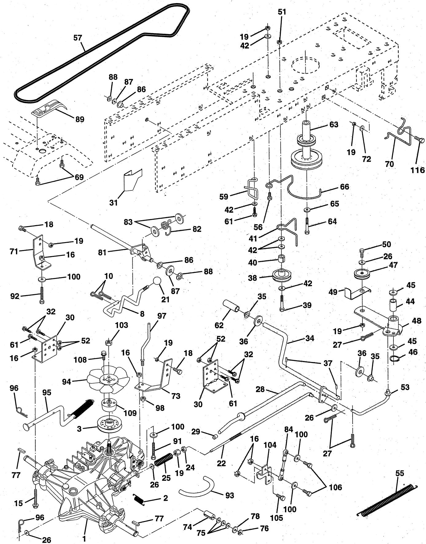
REPAIR PARTS
TRACTOR- -MODEL NO. LTH130 (HCLTH130A), PRODUCT NO. 954 88 00-61 DRIVE
| KEY NO. | PART NO. | DESCRIPTION | KEY NO. | PART NO. | DESCRIPTION |
| 1 | 532140607 | Transaxle Assembly | 61 | 817490612 | Screw Thdrol. 3/8-16 x 3/4 Ty. TT |
| 2 | 532142431 | Spring, Return, Brake | 62 | 532124872 | Cover, Pedal |
| 3 | 532144698 | Pulley, Transaxle | 63 | 532140186 | Pulley, Engine |
| 8 | 532141003 | Rod Shift Hydro LT | 64 | 871170764 | Bolt, Hex |
| 10 | 876020416 | Pin Cotter 1/8 x 1 CAD | 65 | 810040700 | Washer |
| 15 | 874490544 | Bolt Hex Flghd 5/16-18 Gr 5 | 66 | 532129921 | Keeper Belt Engine |
| 16 | 873800500 | Nut Lock Hex W/Ins 5/16-18 Unc P | 69 | 532142432 | Screw |
| 18 | 874780616 | Bolt Fin Hex 3/8-16 Unc x 1 Gr. 5 | 70 | 532134683 | Keeper Belt Engine |
| 19 | 873800600 | Nut Lock Hex W/Wsh 3/8-16 Unc | 71 | 532141417 | Strap Torque Lh Hydro 500 18" |
| 21 | 532140845 | Knob 1/2-13 | 72 | 819132012 | Washer 13/32 x 1-1/4 x 12 Gauge |
| 22 | 532145627 | Rod, Brake Hydro | 73 | 532141418 | Strap Torque Rh Hydro 500 18" |
| 24 | 873350600 | Nut | 74 | 532121199 | Spacer, Split |
| 25 | 532106888 | Spring, Brake Rod | 75 | 532121749 | Washer 25/32 x 1-1/4 x 16 Gauge |
| 26 | 819131316 | Washer | 76 | 812000001 | E-Ring |
| 27 | 876020412 | Pin Cotter 1/8 x 3/4 CAD. | 77 | 532123583 | Key, Square |
| 28 | 532145204 | Rod, Parking Brake | 78 | 532121748 | Washer 25/32 x 1-5/8 x 16 Gauge |
| 29 | 532071673 | Cap, Parking Brake | 81 | 532141420 | Shaft Asm. Cross Hydro 500 |
| 30 | 532130807 | Bracket, Transaxle | 82 | 532123782 | Spring Torsion T/A |
| 31 | 532127275 | Keeper Belt Lh | 83 | 819171216 | Washer 17/32 x 3/4 x 16 Ga. |
| 32 | 874760512 | Bolt Hex Hd 5/16-18 Unc x 3/4 | 84 | 532141423 | Rod, Tie Hydro Sph Ball 500 |
| 34 | 532149001 | Shaft, Foot Pedal | 86 | 532071208 | Bushing Rod Strig. 629/632 ID |
| 35 | 532120183 | Bearing, Nylon | 87 | 819212016 | Washer 21/32 x 1-1/4 x 16 Ga. |
| 36 | 819211616 | Washer | 88 | 812000008 | Ring Klip #5304-62 |
| 37 | 532124963 | Pin, Roll | 89 | 532139988 | Console, Shift |
| 38 | 532123674 | Pulley, Idler, Flat | 91 | 874780536 | Bolt Fin Hex 5/16-18 x 2-1/4 |
| 39 | 874760644 | Bolt | 92 | 874780524 | Bolt Fin Hex 5/6-18 Unc x 1-1/2 |
| 40 | 532124965 | Spacer, Split | 93 | 532142564 | Line Fuel Hydro 4" |
| 41 | 532109070 | Keeper, Belt Retainer | 94 | 532140462 | Fan, Hydro 7" |
| 42 | 819131312 | Washer 13/32 x 13/16 x 12 Gauge | 95 | 532144643 | Control Asm. Bypass Hydro |
| 44 | 532105706 | Bearing, Nylon | 96 | 532124788 | Retainer Spring 1" Zinc/Cad |
| 45 | 532110812 | Washer, Hardened | 97 | 532144201 | Keeper Belt Rh Hydro 500 |
| 46 | 812000039 | Ring, Klip | 98 | 873510600 | Nut Keps Hex 3/8-16 Unc |
| 47 | 532127783 | Pulley, Idler, V-Groove | 100 | 819111216 | Washer 11/32 x 3/4 x 16 Ga. |
| 48 | 532123789 | Bellcrank Assembly | 103 | 873940800 | Nut, Hex Jam Toplock 1/2-20 Unf |
| 49 | 532123205 | Retainer, Belt | 104 | 532141421 | Arm, Control Pump |
| 50 | 874760624 | Bolt | 105 | 871070516 | Screw Cap Hex 5/16 x 18 x 1 |
| 51 | 873680600 | Nut Crownlock 3/8-16 | 106 | 874780520 | Bolt Fin Hex 5/16-18 Unc x 1-1/4 |
| 52 | 873680500 | Nut Crownlock 5/16-18 | 108 | 817541026 | Screw Hex Wh Hd #10-24 x 1-5/8 |
| 53 | 532105710 | Link, Clutch | 109 | 532145098 | Adaptor Fan/Hydro Lt Hyd Alum |
| 55 | 532105709 | Spring, Return, Clutch | |||
| 56 | 874760620 | Bolt Fin Hex 3/8-16 Unc x 1-1/4 | |||
| 57 | 532141416 | V-Belt, Ground Drive | |||
| 59 | 532140312 | Keeper, Center Span |
REPAIR PARTS
TRACTOR- -MODEL NO. LTH130 (HCLTH130A), PRODUCT NO. 954 88 00-61 STEERING AND FRONT AXLE
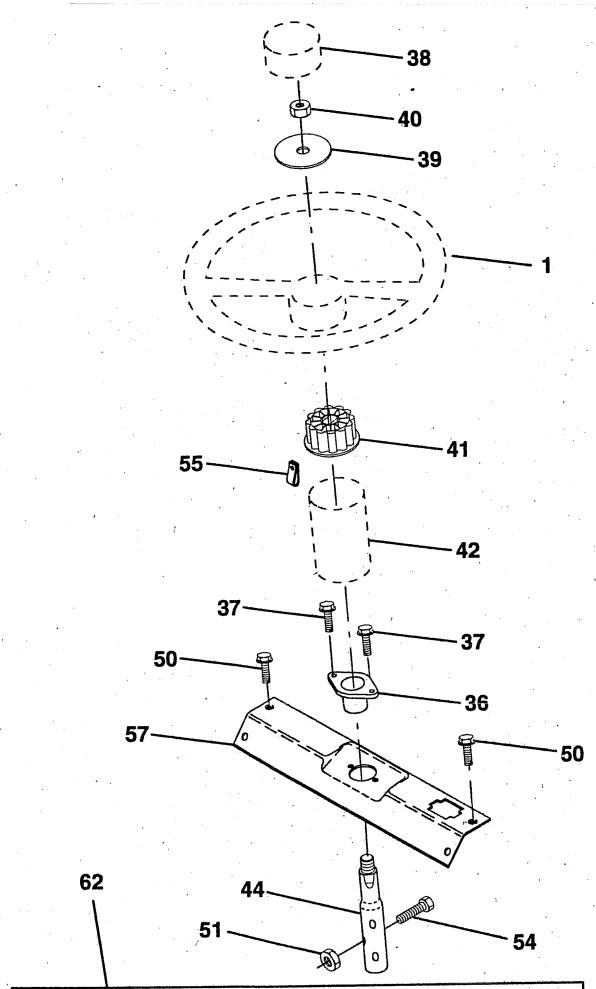
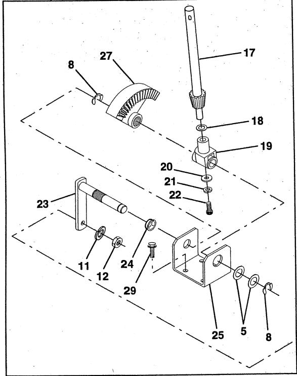
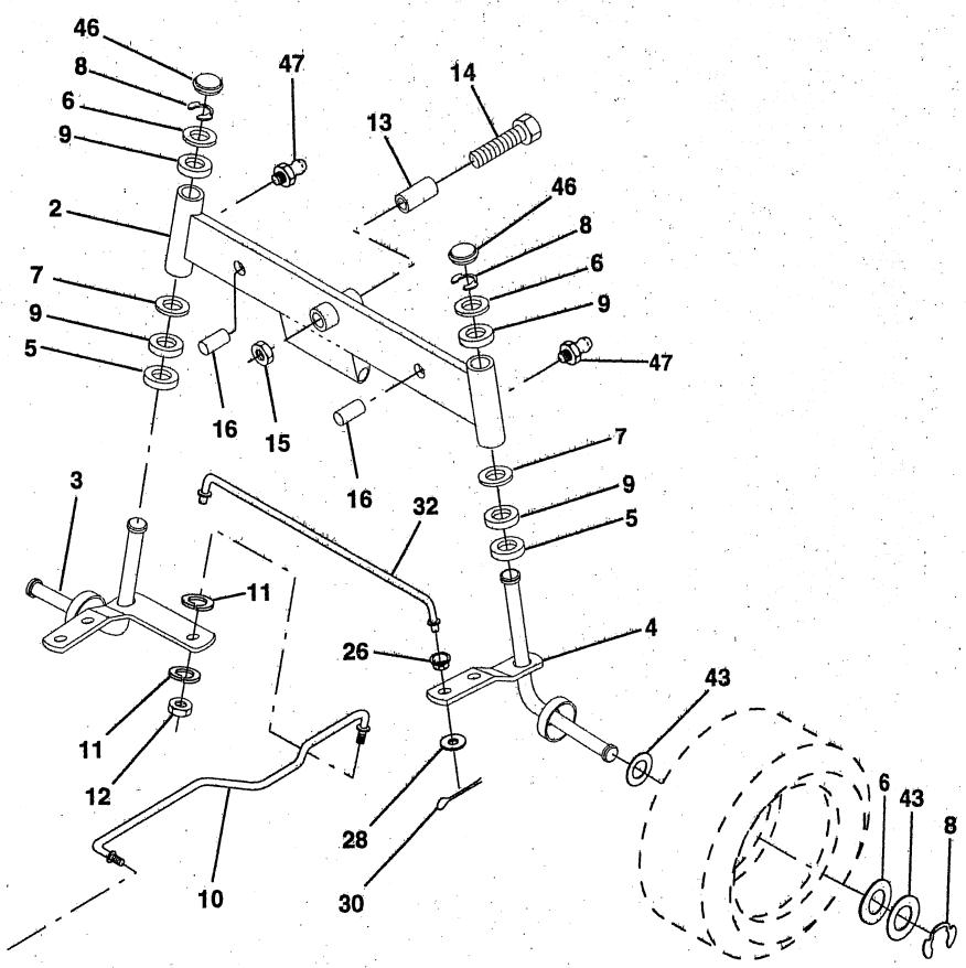
REPAIR PARTS
TRACTOR- -MODEL NO. LTH130 (HCLTH130A), PRODUCT NO. 954 88 00-61 STEERING AND FRONT AXLE
| KEY NO. | PART NO. | DESCRIPTION |
| 1 | 532124415 | Wheel Steering Auto Grey |
| 2 | 532142033 | Axle Asm Fr LT W/gzks 38/42 |
| 3 | 532135227 | Spindle Asm LH |
| 4 | 532135228 | Spindle Asm RH |
| 5 | 532124931 | Bearing Race Thrust Harden |
| 6 | 532121748 | Washer 25/32 X 1-5/8 X 16ga |
| 7 | 819272016 | Washer 27/32 X 1-1/4 X 16 Ga |
| 8 | 812000029 | Ring Klip #t5304-75 |
| 9 | 532124937 | Bearing Col Strg Blk |
| 10 | 532130468 | Link Drag Sol Ball Jt 20 064 |
| 11 | 810040600 | Washer Lock Hvy Hcl Spr 3/8 |
| 12 | 873610600 | Nut Fin Hex 3/8-24 Unf |
| 13 | 532110438 | Spacer Bearing Axle Front |
| 14 | 874011056 | Bolt Hex 5/8-11 Unc X 3-1/2 |
| 15 | 873901000 | Nut Lock Flange 5/8-11 Unc |
| 16 | 532132624 | Pin Axle 5/8 X 1 55/1 54 Lg |
| 17 | 532140176 | Shaft Asm Strg Private Label |
| 18 | 532057079 | Washer Thrust 515x 750x 033 |
| 19 | 532124035 | Support Shaft |
| 20 | 532126684 | Washer Shim 1/4 X 5/8 X 062 |
| 21 | 810040400 | Washer Lock Hvy Helical 1/4 |
| 22 | 871070410 | Screw Hex Socket 1/4-20 X 5/8 |
| 23 | 532127501 | Shaft Asm Pittman |
| 24 | 532109816 | Nyliner Snap In |
| 25 | 532124036 | Bracket Steering |
| KEY NO. | PART NO. | DESCRIPTION |
| 26 | 532126847 | Bushing Link Drag Blk LR |
| 27 | 532136874 | Gear Sector 22 Teeth |
| 28 | 819131416 | Washer 13/32 X 7/8 X 16ga |
| 29 | 817490612 | Screw Thdrol 3/8-16x3/4 Ty-tt |
| 30 | 876020412 | Pin Cotter 1/8 X 3/4 Cad |
| 32 | 532130465 | Rod Tie Wire Form 19 75 Mech |
| 36 | 532102803 | Bushing Strg |
| 37 | 817431008 | Screw Slftp #10-16 X 1/2 Ty-b |
| 38 | 532124416 | Insert Cap Strg Wh Au Gen Grey |
| 39 | 819133808 | Washer 13/32 X 2-3/8 X 8 Ga |
| 40 | 532124701 | Nut Lock Center 3/8-24unf |
| 41 | 532104820 | Adaptor Wheel Strg 640/ 635id |
| 42 | 532150390 | Boot Shaft Steering |
| 43 | 532121749 | Washer 25/32 X 1 1/4 X 16 Ga |
| 44 | 532146690 | Shaft Extension Steering |
| 46 | 532121232 | Cap Spindle Fr Top Blk |
| 47 | 532124836 | Fitting Grease |
| 50 | 817490412 | Screw Hex Wsh Thdrol 1/4-20 x 3/4 |
| 51 | 873800500 | Nut Lock Hex w/Insert 5/16-18 |
| 54 | 874780520 | Bolt Fin Hex 5/16-18 unc x 1-1/4 |
| 55 | 532140285 | Clip Tinnerman |
| 57 | 532140172 | Support Shaft Steering |
| 62 | 532149686 | Kit, Steering Assembly |
NOTE: All component dimensions given in U.S. inches. 1 inch = 25.4 mm
REPAIR PARTS
TRACTOR- -MODEL NO. LTH130 (HCLTH130A), PRODUCT NO. 954 88 00-61 ENGINE
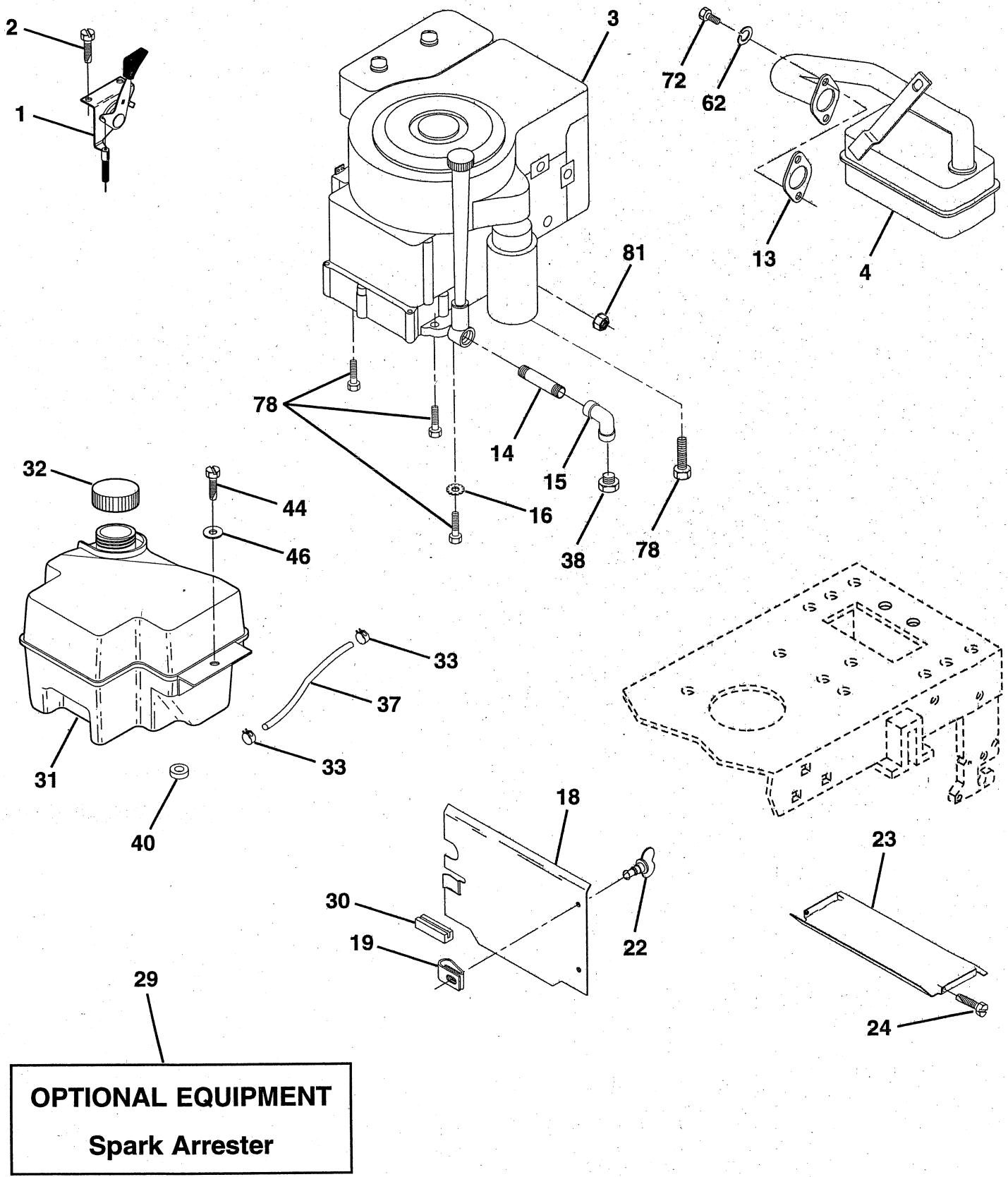
REPAIR PARTS
TRACTOR- -MODEL NO. LTH130 (HCLTH130A), PRODUCT NO. 954 88 00-61 ENGINE
| KEY NO. | PART NO. | DESCRIPTION |
| 1 | 532140310 | Control Th/ch RH Blk Tee Eec |
| 2 | 817720410 | Screw Hex Thd Cut 1/4-20x5/8 T |
| 3 | -------- | Engine, B&S 12.5 ICQ/13 D/IC 1 DC Model No. 28M707 |
| 4 | 532137348 | Muffler LT B&s 12/12.5 HP |
| 13 | 532272293 | Gasket Eng 1 313 Id Tin Plated |
| 14 | 813280324 | Nipple Pipe 3/8 Npt X 3" |
| 15 | 813200300 | Elbow Std 90 Degree 3/8-18 Npt |
| 16 | 811050600 | Washer Lock Ext Tooth 3/8 |
| 18 | 532136718 | Shield Heat LT |
| 19 | 532105839 | Receptacle 1/4 Turn dacrotized |
| 20 | 532105838 | Retainer 1/4 Turn 365 OD x .222 ID |
| 21 | 819091016 | Washer 9/32 x 5/8 x 16 Ga |
| 22 | 532123650 | Stud 1/4 Turn (replaces 105751) |
| 23 | 532128953 | Shield Heat Browning LT/YT |
| 24 | 817021008 | Screw Tap Hex #10-24unc X 1/2 |
| 29 | 532137180 | Kit Spark Arrestor 1 25 |
| 30 | 532127057 | Pinch Weld Hood Black 2.00 |
| 31 | 532140280 | Tank Fuel Front 2.00 |
| 32 | 532140527 | Cap Asm Fuel W/sym Vented |
| 33 | 532123487 | Clamp Hose Blk |
| 37 | 532137040 | Line Fuel 9 20" |
| 38 | -------- | Plug Oil Drain (Order From Engine Manufacturer) |
| 40 | 532124028 | Bushing Snap Nyl Blk Fuel Line |
| 44 | 817490412 | Screw Hexwsh Thdrol 1/4-20x3/4 |
| 46 | 819091416 | Washer 9/32 X 7/8 X 16ga |
| 62 | 810040500 | Washer Lock Hvy Hcl Spr 5/16 |
| 72 | 871070512 | Screw Hexhd Cap 5/16-18x3/4 |
| 78 | 817490620 | Screw Thdrol 3/8-16x1-1/4 TYTT |
| 81 | 532128861 | Nut Flange 1/4-20 Starter Nut |
NOTE: All component dimensions given in U.S. inches. 1 inch = 25,4 mm.
REPAIR PARTS
TRACTOR- -MODEL NO. LTH130 (HCLTH130A), PRODUCT NO. 954 88 00-61 SEAT
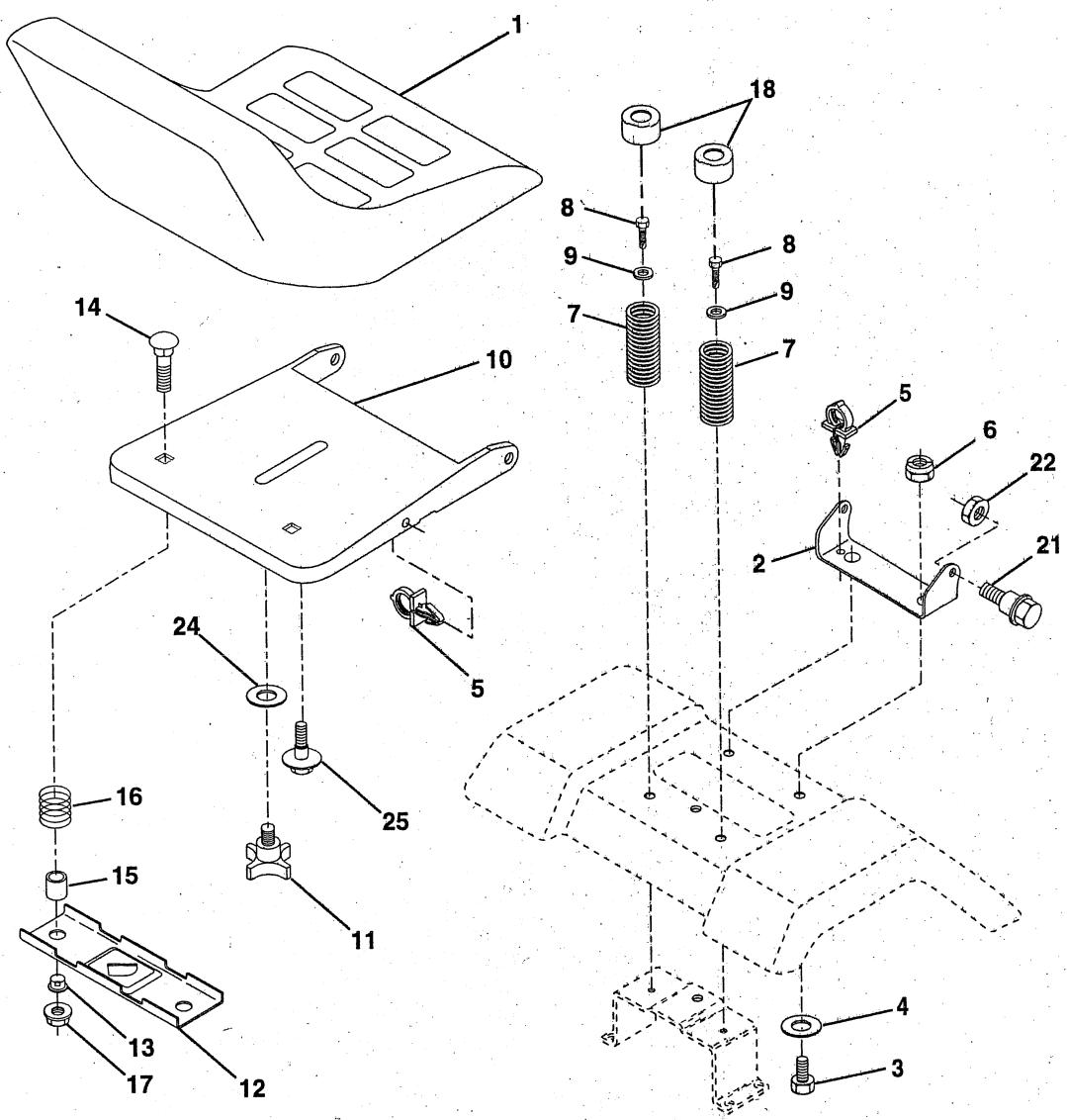
KEY PART NO. NO.
1 532127398
2 532140551
3 874760616
4 819131610
5 532145006
6 873800600
7 532124181
8 817490616
9 819131614
0 532140552
11 532120068
12 532121246
13 532121248
DESCRIPTION
Seat
Bracket Pivot Seat 8720
Bolt Fin Hex 3/8-16unc X 1
Washer 13/32 X 3/4 X 10 Ga
Clip Push-In Hinged
Nut Lock Hex w/Ins 3/8-16 Unc
Spring Seat Cprsn 2 250 Blk Zi
Screw Thdrol 3/8-16 X 1 Ty- tt
Washer 13/32 X 1 X 14 Ga
Pan Seat
Knob Seat 1/2-13unc Blk
Bracket Mounting Switch
Bushing Snap Bk Nyl 50 Id
KEY PART NO. NO.
DESCRIPTION
14 872050411 Bolt Rdhd Sht Nk 1/4-20x1-3/8
15 532134300 Spacer Split 28x 96 Yel Zinc
16 532121250 Spring Cprsn 1 27 Blk Pnt
17 532123976 Nut Lock 1/4 Lge Flg Gr 5 Zinc
18 532124238 Cap Spring Seat Blk 1.75 x 1.0
21 532139888 Bolt Shoulder 5/16-18 Type T.T.T.R.
22 873800500 Nut Lock 5/16-18
24 819171912 Washer 17/32 X 1-3/16 X 12 Ga
25 532127018 Bolt Shoulder 5/16-18 X 62
NOTE: All component dimensions given in U.S. inches.
1 inch = 25.4 mm
REPAIR PARTS
TRACTOR- -MODEL NO. LTH130 (HCLTH130A), PRODUCT NO. 954 88 00-61 DECALS
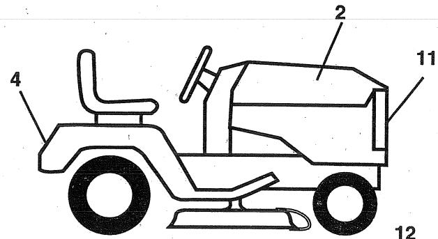
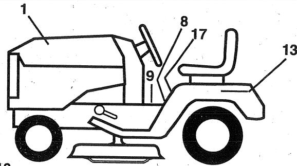
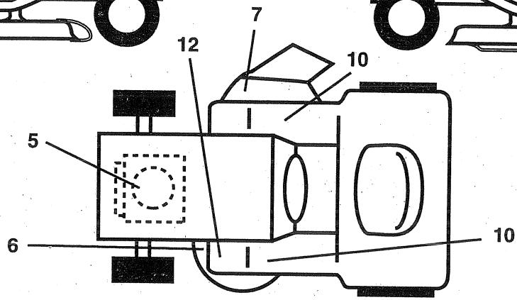
KEY PART
NO. NO.
DESCRIPTION
1 532150726
2 532150725
4 532150617
5 532273212
6 532136832
7 532137259
8 532140820
9 532142337
11 532150616
12 532101892
13 532145005
17 532133795
Decal Hood Husqvarna LH
Decal Hood Husqvarna RH
Decal Fender
Decal Engine 13 HP B&S Dia. I/C
Decal, V-Belt Sch 38"/42" LT
Decal Warning MULT-LANGUAGE
Decal Dash Instructions Operating Eng/Fr
Decal Sdl Cold Start Hydo Eng/Fr
Decal Grille Husqvarna
Decal Clutch/brake Eng/Fr/Ger/Du
Decal Battery Dan/Poi P/L Sym WPN
Decal Caution Fender Eng/Fr
KEY PART
NO. NO.
DESCRIPTION
532138311 Decal Handle Lift Height Adjust
--- 532142341 Decal Drawbar Control
- - 532145246 Pad Footrest Rbr Sq Generic 95
--- 532145247 Fastener Pop In Footrest (8 per)
532151177 Manual Owner's (English)
532151178 Manual Owner's (French)
Available accessories (not included with tractor)
LA018 Tire Chains (18 x 9.5 x 8)
- LSB42 42” Snow Thrower
LBD48 48" Snow Blade
- LC05 33 lb. Wheel Wts. (pair)
- MP42 Mulching Plate for 42"
WHEELS AND TIRES
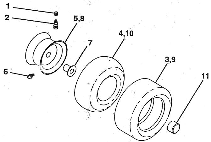
KEY PART
NO. NO.
DESCRIPTION
1 532059192
2 532065139
3 532106222 Tire F Ts 15 X 6 0 - 6 Service
4 532059904 Tube Front (Service Item Only)
5 532138336 Rim Asm 6" front Service
6 532124957 Fitting Grease (Front Wheel Only)
7 532124959 Bearing Flange (Service Item Only)
8 532138337 Rim Asm 8” rear Service
9 . 532106268 – Tire R Ts 18x9 5- 8 C Service
10 532124926 Tube Rear (Service Item Only)
11 532104757 Cap Axle Blk 1 50 X 1 00
--- 532144334 Sealant, Tire (10 oz. Tube)
REPAIR PARTS
TRACTOR- -MODEL NO. LTH130 (HCLTH130A), PRODUCT NO. 954 88 00-61 LIFT
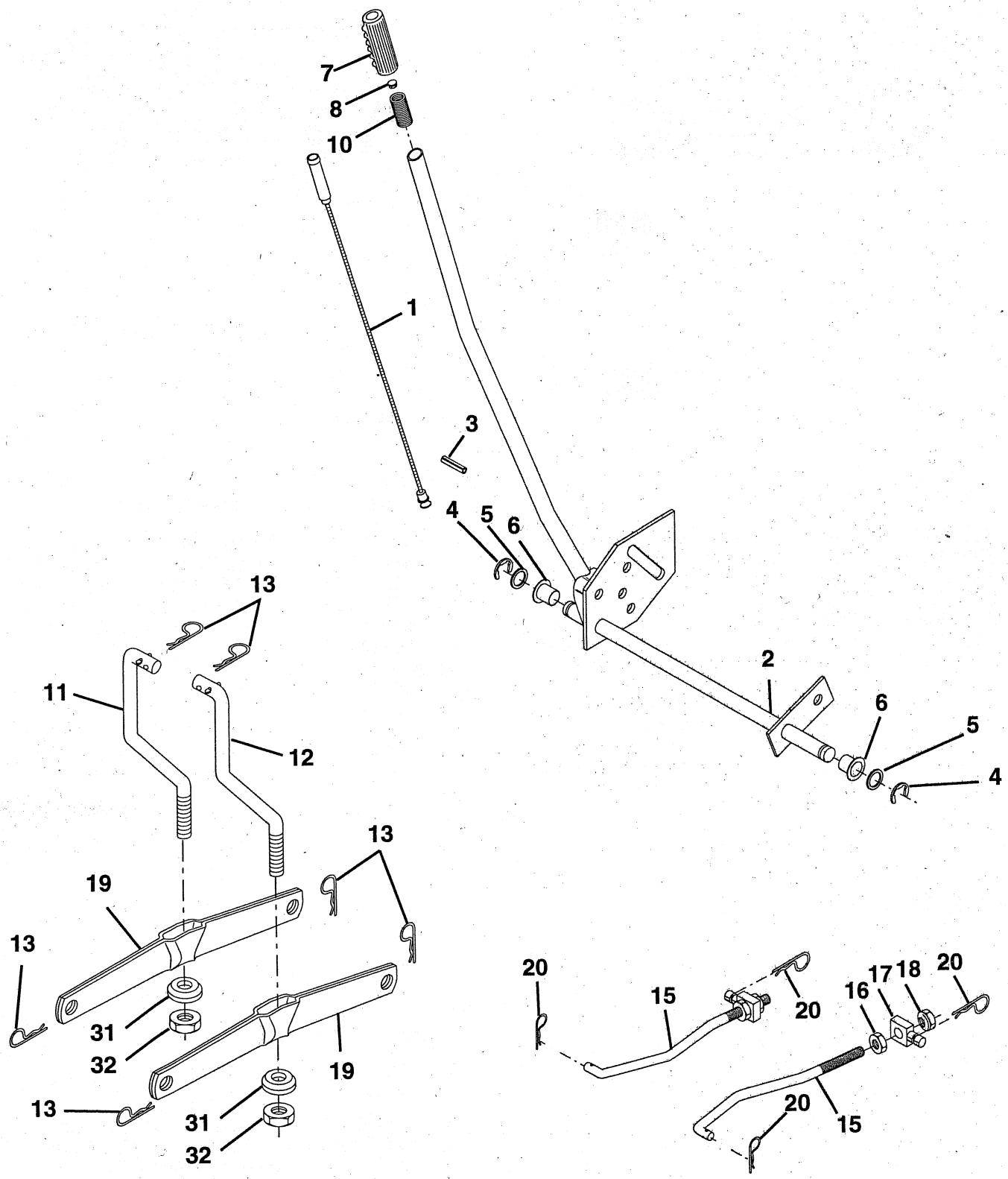
REPAIR PARTS
TRACTOR- -MODEL NO. LTH130 (HCLTH130A), PRODUCT NO. 954 88 00-61 LIFT
KEY PART
NO. NO.
DESCRIPTION
1 532136973
2 532150588
3 532138284
4 812000002
5 819211621
6 532120183
7 532109413
8 532124526
0 532122512
11 532139865
12 532139866
13 532124670
15 532127218
16 873350800
17 532130171
18 873800800
19 532139868
20 532124660
31 532140302
32 873540600
Wire Asm Inner w/plunger
Handle Asm Lift Lh Inf P/L
Pin Groove
E Ring #5133-62
Washer PLTD 21/32 X 1 X 21ga
Bearing Nylon Blk 629 Id
Grip Handle Bicycle Matte Blk
Button Plunger Black
Spring Cprsn 3 750 Oiled
Link Lift LH
Link Lift RH
Retainer Spring
Link Front
Nut Jam Hex 1/2-13 Unc
Trunnion Bulk Zinc
Nut Lock W/wsh 1/2-13unc
Arm Suspension Rear
Retainer Spring
Bearing Pivot Lift Spherical
Nut Crownlock 3/8-24
NOTE: All component dimensions given in U.S. inches 1 inch = 25.4 mm
REPAIR PARTS
TRACTOR- -MODEL NO. LTH130 (HCLTH130A), PRODUCT NO. 954 88 00-61 MOWER DECK
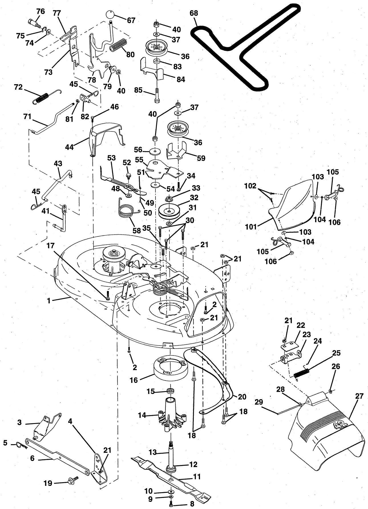
REPAIR PARTS
TRACTOR- -MODEL NO. LTH130 (HCLTH130A), PRODUCT NO. 954 88 00-61 MOWER DECK
| KEY | PART |
| NO. | NO. |
1 532144393
2 872140506
3 532138017
4 532138440
5 532124670
6 532130832
8 532850857
9 810030600
10 532140296
11 532134149
12 532129895
13 532137645
14 532128774
15 532110485
16 532140329
17 872110610
18 872140505
19 532132827
20 532136888
21 873680500
22 532134753
23 532131267
24 532105304
25 532123713
26 532110452
27 532130968
28 819111016
29 532131491
30 532138776
31 532129963
32 532129861
33 532137266
34 872110614
35 532133835
36 532131494
37 819131316
40 873680600
41 532133551
43 532140083
44 532140088
45 532124788
46 532137729
DESCRIPTION
Deck Asm Mower 42"
Bolt Rdhd Sqnk 5/16-18unc X3/4
Bracket ASM Fr Sway Bar
Bracket Asm Deck Sway Bar 42"
Retainer Spring
Arm Suspension Rear
Bolt 3/8-24x1 25 Gr8 Patched
Washer Lock Hwy 3/8 Unplated
Washer Hard Blade Mower Vented
Blade
Bearing Ball #6204 (Mandrel)
Shaft Asm W/lower Bearing
Housing Mandrel Vented(machd)
Bearing Ball Mandrel
Stripper Mower Vented
Bolt Rdhd Sqnk 3/8-16 X 1-1/4
Bolt Rdhd Sqnk 5/16-18 X 5/8
Bolt Shoulder 5/16 - 18
Baffle Vortex 42
Nut Crownlock 5/16-18
Stiffener Bracket 42" deck
Bracket Deflector Mower 42"
Cap Sleeve 80x 112 Blk Mower
Spring Torsion Deflector 2 52
Nut Push Phos & Oil
Shield Deflector Mower 42" Blk"
Washer 11/32 X 5/8 X 16 Ga
Röd Hinge 42" 6 75 Wlg
Screw Thdrol Hex Head
Washer Spacer Mower Vented
Pulley Mandrel 42"
Nut Flg Top Lock Cntr B 9/16
Bolt Rdhd 3/8-16uncx1-3/4 Gr5
Fastner Christmas Tree
Pulley Idler Flat 3 060
Washer 13/32 X 13/16 X 16 Ga
Nut Crownlock 3/8-16
Rod Pivot W/nibs
Rod Clutch Secondary W/nibs
Guard Mandrel LH Black
Spring Retainer 1" Zinc/cad
Screw Hex Thd Cut 1/4-20x5/8 T
DESCRIPTION
| KEY | PART |
| NO. | NO. |
48 532133944
49 532133940
50 532131340
51 532069180
52 532139888
53 532131845
54 532133943
55 532140084
56 532122052
58 532140086
59 532141043
67 532106933
68 532144200
71 532142427
72 532131870
73 532127847
74 532121748
75 812000029
76 532128903
77 532127845
78 532140179
79 532127498
80 532128759
81 873350600
82 532142028
83 532120958
84 532144394
85 872140618
101 532136420
102 871161010
103 810071000
104 819061216
105 532130758
06 532125004
-- 532130794
-- 532145411
Washer Hardened Smaller
Roller Asm Cam Follower 42" dec
Bolt Shldr 10-24 Zinc Gr 5 42"
Nut Lock #10-24 Unc Bolt Shoulder 5/16-18
Arm Asm Pad Brake
Washer HardenedArm Idler 42" mower LT/YT
Spacer Retainer Pm Mower
Spring Torsion Brakes
Guard Tuv Idler Knob Rd 1/2-13 Plstc Thds Blk
V-Belt Mower
Rod Clutch Primary 38/42
Spring Return Arm Clutch Secondary
Washer 25/32 X 1- 5/8 X 16 Ga ®
Ring Klip #t5304-75
Bolt Shoulder 3/8- 16 Unc 1 44
Keeper Spring 4 000
Arm ASM Clutch Primary
Bushing 747 Od X 794 Lq Brass
Spring Clutch Mower 2 750 Zinc
Nut Hex Jam 3/8-16 unc
Trunnion Adj.
Washer Sintered
Keeper Belt Idler Fixed
Bolt Carriage 3/8-16 x 2-1/4 Gr.5
Cover Mulching 42" Black
Screw
Washer Lock #10
Washer #10
Latch Asm Bagger
Nut Weld .3277.304 #10-24
Mandrel Asm Service (Includes Key)
Nos. 8-10, 12-15, 31 and 33)
Deck Serv 42" mech (Std. Deck -
Order Mulcher Plate Components
separately-KeyNos.101-106)
NOTE: All component dimensions given in U.S. inches. 1 inch = 25.4 mm
REPAIR PARTS
TRACTOR- -MODEL NO. LTH130 (HCLTH130A), PRODUCT NO. 954 88 00-61 HYDRO-GEAR TRANSAXLE - MODEL NO. 319-0500
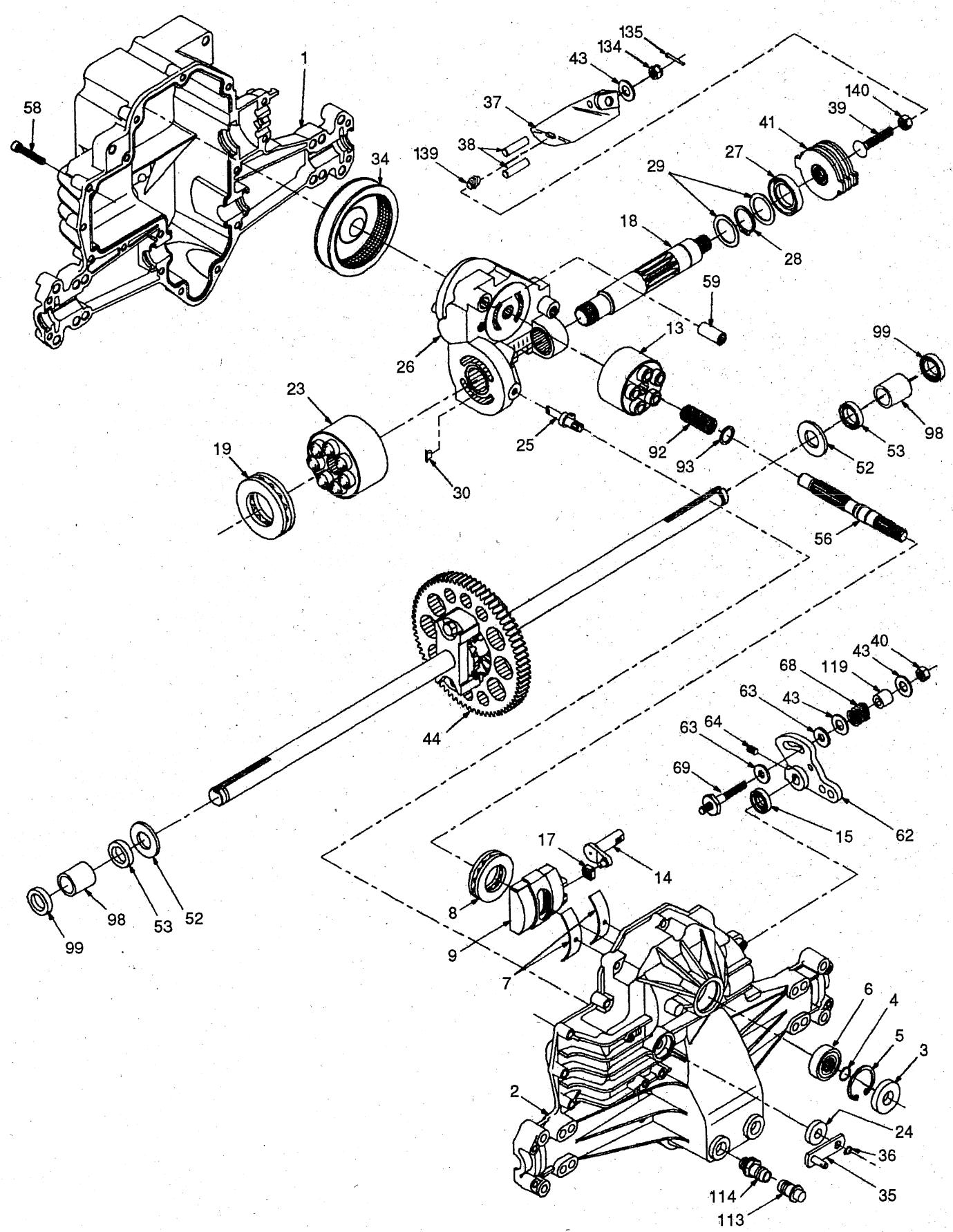
REPAIR PARTS
TRACTOR- -MODEL NO. LTH130 (HCLTH130A), PRODUCT NO. 954 88 00-61 HYDRO-GEAR TRANSAXLE - MODEL NO. 319-0500
KEY PART NO. NO.
| 1 | 532142986 | Housing, Lower |
| 2 | 532142987 | Assembly, Upper Housing |
| 3 | 532142932 | Seal, Lip |
| 4 | 532142928 | Ring, Wire Retaining |
| 5 | 532142933 | Ring, Retaining |
| 6 | 532142934 | Bearing, Shaft Ball |
| 7 | 532142935 | Bearing, Cradle |
| 8 | 532150771 | Bearing, Thrust 30 x 52 x 13 |
| 9 | 532142937 | Swashplate, Variable |
| 13 | 532142938 | Block, Cylinder Assembly |
| 14 | 532142939 | Arm, Trunnion |
| 15 | 532142940 | Seal, Lip |
| 17 | 532142941 | Guide, Slot |
| 18 | 532150772 | Shaft, Motor |
| 19 | 532150773 | Bearing, Thrust 42 x 68 x 16 |
| 23 | 532142944 | Block, Cylinder Assembly |
| 24 | 532142945 | Seal, Lip 10 x 25 x 7 |
| 25 | 532142946 | Actuator, Bypass |
| 26 | 532150774 | Center Section Assembly Kit |
| 27 | 532142948 | Seal, Lip 26 x 42 x 8 |
| 28 | 532142949 | Ring, Retaining |
| 29 | 532142950 | Washer 26 x 35 x 1 |
| 30 | 532150787 | Nut, Jam |
| 34 | 532142951 | Oil Filter Element |
| 35 | 532142952 | Arm, Bypass |
| 36 | 532142953 | Ring, Retaining |
| 37 | 532142954 | Arm, Actuating |
| 38 | 532142955 | Pin, Actuating |
| 39 | 532150777 | Bolt 5/16-24 x 1-3/4 |
KEY PART NO. NO.
| 40 | 532150778 | Locknut, Hex 5/16-24 UNJC |
| 41 | 532142958 | Brake Rotor/Stator Kit |
| 43 | 532142884 | Washer 7/16 x 7/8 x .060 |
| 44 | 532142990 | Differential Assembly |
| 52 | 532142991 | Washer 3/4 x 1.5 x .13 |
| 53 | 532142961 | Seal .75 x 1.25 x .250 |
| 56 | 532142963 | Shaft, Input |
| 58 | 532142964 | Bolt 1/4-20 x 1.38 |
| 59 | 532142965 | Pin .5 OD x .43 ID x .750 |
| 62 | 532142966 | Arm, Control |
| 63 | 532142967 | Puck, Dampener |
| 64 | 532142920 | Set Screw |
| 68 | 532142969 | Spring |
| 69 | 532144610 | Stud 5/16-24 |
| 92 | 532142977 | Spring, Block |
| 93 | 532142978 | Washer, Block Thrust |
| 98 | 532142993 | Sleeve Bearing |
| 99 | 532142976 | Seal, Wiper |
| 113 | 532142917 | Cap, Vent Assembly |
| 114 | 532142918 | Fitting, O-Ring Assembly |
| 119 | 532142980 | Spacer |
| 134 | 532144607 | Nut, Castle 5/16-24 |
| 135 | 532144608 | Pin, Cotter |
| 139 | 532150775 | Spring, Compression |
| 140 | 532150776 | Nut, Hex 5/16-24 |
NOTE: All component dimensions given in U.S. inches 1 inch = 25.4 mm

Operate your Tractor up and down the face of slopes (not greater than 15^ ), never across the face. Make turns gradually to prevent tipping or loss of control. Exercise extreme caution when changing direction on slopes.

Husqvarna
SECTION 1: LIMITED WARRANTY
Husqvarna Forest & Garden Company ("Husqvarna") warrants Husqvarna product to the original purchaser to be free from defective material and workmanship from the date of purchase for the "Warranty Period" here stated dependent upon the type of product use. Warranty period is as follows for products listed: 5 Year Warranty: Plastic walk behind mower decks for noncommercial, noninstitutional or nonincome producing use.
2 Year Warranty: Riding lawn mowers, yard and garden tractors, walk behind mowers, tillers and attachments for noncommercial, noninstitutional or nonincome producing use. Ignition coils or modules on the chain saws, clearing saws and trimmers.
1 Year Warranty: Chain saws, clearing saws, trimmers, blowers and batteries for noncommercial, noninstitutional or nonincome producing use.
90 Day Warranty: Any Husqvama product used for rental, commercial, professional, or income pro use.
30 Day Warranty: Husqvarna professional bow bars.
30 Day Replacement Part Warranty: Unless otherwise stated, replacement parts are warranted for 30 days from date of purchase.
SECTION 2: HUSQVARNA'S OBLIGATIONS UNDER THE WARRANTY Husqvarna will remedy defects in material and workmanship during the warranty period by repairing or replacing, at Husqvarna's option, the defective component without charge for parts or labor.
SECTION 3: ITEMS NOT COVERED BY THIS WARRANTY
The following items are not covered by the
(1) Normal customer maintenance items (i.e., belts, blades, blade adapters, bulbs, filters, guide bars, lubricants, rewind springs, saw chain, spark plugs, starter ropes and tines).
(2) Normal wear, normal adjustment, standard hardware or items worn through regular use.
(3) Natural discoloration of material due to ultraviolet light.
(4) The replacement or maintenance of worn items.
(5) Briggs & Stratton, Kawasaki and Kohler engines, including starters, generators, alternators and accessories. These items are covered by the engine manufacturer's warranty as stated with the product information supplied at the time of purchase. All claims for specified engines, starters, generators, alternators and accessories should be sent to the appropriate manufacturer.
(6) Agri-Fab, Foote, and Tecumseh-Peerless drive systems. These items are covered by the drive system manufacturer's warranty as stated with the product information supplied at the time of purchase. All claims for specified drive systems should be sent to the appropriate manufacturer.
SECTION 4: EXCEPTIONS AND LIMITATIONS
This warranty shall be inapplicable to defects resulting from the following:
(1) Accident, abuse, misuse, negligence and neglect, including stale fuel, dirt abrasives, moisture, rust, corrosion, or any adverse reaction due to incorrect storage habits.
- HcLTH1304
- GENERAL OPERATION
- SLOPE OPERATION
- DO:
- DO NOT:
- CHILDREN
- SERVICE
- CUSTOMER RESPONSIBILITIES
- INDEX
- A
- B
- C
- E
- F
- H
- L
- M
- 0
- P
- R
- s
- T
- W
- Parts Bag contents shown full size
- Parts packed separately in carton
- Parts bag contents not shown full size
- TOOLS REQUIRED FOR ASSEMBLY
- TO REMOVE TRACTOR FROM CARTON
- UNPACK CARTON
- BEFORE ROLLING TRACTOR OFF SKID
- ATTACH STEERING WHEEL (See Fig. 1)
- ASSEMBLE EXTENSION SHAFT
- INSTALL STEERING WHEEL
- TO ROLL TRACTOR OFF SKID (See Operation section for location and function of controls)
- CONNECT BATTERY (See Figs. 2 and 3)
- INSTALL SEAT (See Fig. 4)
- INSTALL MULCHER PLATE (See Figs. 5 and 6)
- TO CONVERT TO BAGGING OR DISCHARGING
- ASSEMBLY
- CHECK TIRE PRESSURE
- CHECK DECK LEVELNESS
- CHECK FOR PROPER POSITION OF ALL BELTS
- CHECK BRAKE SYSTEM
- √CHECKLIST
- KNOW YOUR TRACTOR
- READ THIS OWNER'S MANUAL AND SAFETY RULES BEFORE OPERATING YOUR TRACTOR
- HOW TO USE YOUR TRACTOR
- TO SET PARKING BRAKE (See Fig. 8)
- STOPPING (See Fig. 8)
- TO USE THROTTLE CONTROL (See Fig. 8)
- TO MOVE FORWARD AND BACKWARD (See Fig. 8)
- TO ADJUST MOWER CUTTING HEIGHT (See Fig. 8)
- TO OPERATE MOWER (See Fig. 9)
- TO OPERATE ON HILLS
- TO TRANSPORT (See Figs. 7 and 10)
- BEFORE STARTING THE ENGINE CHECK ENGINE OIL LEVEL (See Fig. 15)
- ADD GASOLINE
- TO START ENGINE (See Fig. 7)
- PURGE TRANSMISSION
- CAUTION: Never engage or disengage freewheel lever while the engine is running.
- MOWING TIPS
- MULCHING MOWING TIPS
- GENERAL RECOMMENDATIONS
- BEFORE EACH USE
- TRACTOR
- BRAKE OPERATION
- TIRES
- BLADE CARE
- BLADE REMOVAL (See Fig. 13)
- TO SHARPEN BLADE (See Fig. 14)
- BATTERY
- TO CLEAN BATTERY AND TERMINALS
- V-BELTS
- TRANSAXLE COOLING
- TRANSAXLE PUMP FLUID
- ENGINE
- LUBRICATION
- AIR FILTER (See Fig. 16)
- CLEAN AIR SCREEN (See Fig. 17)
- ENGINE COOLING FINS (See Fig. 17)
- MUFFLER
- SPARK PLUGS
- IN-LINE FUEL FILTER (See Fig. 18)
- CLEANING
- CAUTION: BEFORE PERFORMING ANY SERVICE OR ADJUSTMENTS:
- TO REMOVE MOWER (See Fig. 19)
- TO INSTALL MOWER (See Fig. 19)
- TO LEVEL MOWER HOUSING
- SERVICE AND ADJUSTMENTS
- TO REPLACE MOWER BLADE DRIVE BELT (See Fig. 24)
- BELT REMOVAL -
- BELT INSTALLATION -
- TO ADJUST BRAKE (See Fig. 25)
- TO REPLACE MOTION DRIVE BELT (See Fig. 26)
- TO ADJUST MOTION CONTROL LEVER (See Fig. 27)
- TRANSMISSION REMOVAL/REPLACEMENT
- TO ADJUST STEERING WHEEL ALIGNMENT
- FRONT WHEEL TOE-IN/CAMBER
- TO REMOVE WHEEL FOR REPAIRS (See Fig. 28)
- TO START ENGINE WITH A WEAK BATTERY (See Fig. 29)
- TO ATTACH JUMPER CABLES -
- TO REPLACE HEADLIGHT BULB
- INTERLOCKS AND RELAYS
- TO REPLACE FUSE
- TO REMOVE HOOD AND GRILL ASSEMBLY (See Fig. 30)
- TO ADJUST THROTTLE CONTROL CABLE (See Fig. 31)
- TO ADJUST CARBURETOR (See Fig. 32)
- ACCELERATION TEST -
- STORAGE
- FUEL SYSTEM
- ENGINE OIL
- CYLINDERS
- OTHER
- TRACTOR- -MODEL NO. LTH130 (HCLTH130A), PRODUCT NO. 954 88 00-61 SCHEMATIC
- WIRING INSULATED CLIPS
- REPAIR PARTS
- TRACTOR- -MODEL NO. LTH130 (HCLTH130A), PRODUCT NO. 954 88 00-61 ELECTRICAL
- KEY PART DESCRIPTION
- NO.
- TRACTOR- -MODEL NO. LTH130 (HCLTH130A), PRODUCT NO. 954 88 00-61 CHASSIS AND ENCLOSURES
- DESCRIPTION
- TRACTOR- -MODEL NO. LTH130 (HCLTH130A), PRODUCT NO. 954 88 00-61 DRIVE
- TRACTOR- -MODEL NO. LTH130 (HCLTH130A), PRODUCT NO. 954 88 00-61 STEERING AND FRONT AXLE
- TRACTOR- -MODEL NO. LTH130 (HCLTH130A), PRODUCT NO. 954 88 00-61 ENGINE
- TRACTOR- -MODEL NO. LTH130 (HCLTH130A), PRODUCT NO. 954 88 00-61 SEAT
- KEY PART NO. NO.
- TRACTOR- -MODEL NO. LTH130 (HCLTH130A), PRODUCT NO. 954 88 00-61 DECALS
- KEY PART
- WHEELS AND TIRES
- TRACTOR- -MODEL NO. LTH130 (HCLTH130A), PRODUCT NO. 954 88 00-61 LIFT
- TRACTOR- -MODEL NO. LTH130 (HCLTH130A), PRODUCT NO. 954 88 00-61 MOWER DECK
- TRACTOR- -MODEL NO. LTH130 (HCLTH130A), PRODUCT NO. 954 88 00-61 HYDRO-GEAR TRANSAXLE - MODEL NO. 319-0500
- Husqvarna
- SECTION 1: LIMITED WARRANTY
- SECTION 4: EXCEPTIONS AND LIMITATIONS
Marque : HUSQVARNA
Modèle : IPL
Catégorie : Tondeuse autoportée