ENT-KT-40-C12 - Contacteur électrique ENTES - Notice d'utilisation et mode d'emploi gratuit
Retrouvez gratuitement la notice de l'appareil ENT-KT-40-C12 ENTES au format PDF.

| Caractéristique | Détails |
|---|---|
| Type de produit | Non catégorisé |
| Dimensions | Non spécifiées |
| Poids | Non spécifié |
| Matériaux | Non spécifiés |
| Utilisation | Non spécifiée |
| Maintenance | Non spécifiée |
| Sécurité | Non spécifiée |
| Informations générales | Non spécifiées |
FOIRE AUX QUESTIONS - ENT-KT-40-C12 ENTES
Questions des utilisateurs sur ENT-KT-40-C12 ENTES
0 question sur cet appareil. Repondez a celles que vous connaissez ou posez la votre.
Poser une nouvelle question sur cet appareil
Téléchargez la notice de votre Contacteur électrique au format PDF gratuitement ! Retrouvez votre notice ENT-KT-40-C12 - ENTES et reprennez votre appareil électronique en main. Sur cette page sont publiés tous les documents nécessaires à l'utilisation de votre appareil ENT-KT-40-C12 de la marque ENTES.
MODE D'EMPLOI ENT-KT-40-C12 ENTES
E/NTES
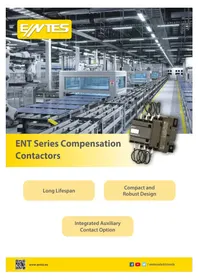
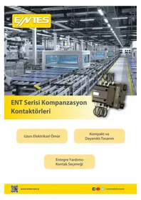
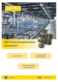
ENT Series Compensation Contactors
natural_image
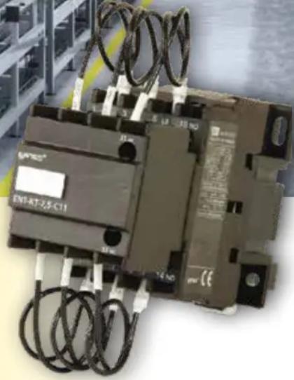
Close-up of an ENF-AT-2,5-C11 electrical contactor with coiled wires and no visible text or symbols on the device itself.Long Lifespan
Compact and Robust Design
Integrated Auxiliary Contact Option
Why Use a Compensation Contactor?
At the moment of switching, a capacitor practically behaves like a short circuit.
The magnitude of the inrush (charging) current depends on the AC voltage level at the moment of switching, as well as the impedance of the supply cable and power transformers.
In single capacitor applications, the peak charging current can reach up to 30 times the capacitor's rated current. For multi-step capacitor banks, inrush currents may exceed 180 times the rated value.
text_image
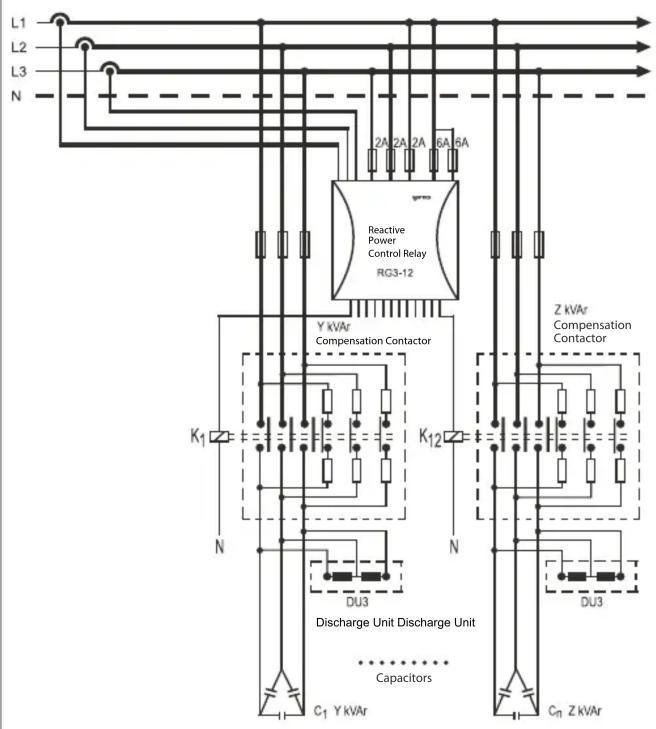
L1 L2 L3 N 2A 2A 2A 6A 6A Reactive Power Control Relay RG3-12 Y kVar Compensation Contactor Z kVar Compensation Contactor K1 K12 N N DU3 Discharge Unit Discharge Unit Capacitors C1 Y kVar DU3 Cn Z kVarThis excessive inrush current may pass through the contactor due to the contribution from both the supply network and the previously connected capacitors. Such current levels can be sufficient to cause welding of the main contacts in standard contactors.
- To limit current fluctuations, add a series damping resistor for fast discharge.
- Make sure to use a specially designed capacitor contactor.
line
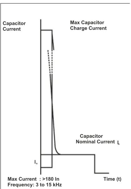
| Time (t) | Capacitor Current | Max Capacitor Charge Current | Capacitor Nominal Current Iₙ | | -------- | ----------------- | ---------------------------- | ---------------------------- | | 0 | 0 | 0 | 0 | | >180 | >180 | 180 | 180 | | 3 to 15 | 0 | 0 | 0 |Working Princible
The ENT Series Capacitor Contactors are specially designed to meet capacitor application requirements. The contactors are equipped with three early-make auxiliary contact blocks and six series-connected resistors—two fast discharge damping resistors per phase. This design limits the inrush current to remain within the contactor's making capacity. The main contacts are designed to carry the normal rated capacitor current, and after closing, effectively short-circuit the resistors.
This design enables safe and reliable switching of capacitor loads with high efficiency.
Product Series
- The contactors are three-phase, rated for 415V AC, 50/60 Hz, with capacities ranging from 2.5 kVAr to 100 kVAr.
• They comply with IEC 60947-4-1 and IS/IEC 60947-4-1 standards for AC-6B utilization category.
Benefits:
- Compliant with IS 13947-4-1 Standard for AC-6B Utilization Category
- Reduces costly spare part expenses.
- Ensures long electrical lifetime.
- Provides low power loss in the 'ON' position, contributing to energy savings.
- Offers high safety.
- Eliminates the risk of dangerous voltage.
- Enables parallel switching of capacitors without requiring power derating.
- Increases operational efficiency with less maintenance and downtime.
Technical Specifications
| "Operating Power (kVAr) 0<55 °C 50/60Hz" | Instantaneous Auxiliary Contacts | Maximum Operations per Hour | Switching Life | |||||
| 220V-240V 400V-440V | ||||||||
| Power (kVAr) | Akım @220V | Power (kVAr) | Akım @400V | NO NC | Number of Uses | |||
| ENT-KT-2,5-C10 1,4 3,67 | 2,5 3,6 1 0 24 | 0 150.000 | ||||||
| ENT-KT-5-C10 2,8 7,34 5 | 7,21 1 0 240 | 150.000 | ||||||
| ENT-KT-7,5-C11 4 10,49 | 7,5 | 10,82 | 1 1 240 200.000 | |||||
| ENT-KT-12-C11 | 6,7 | 17,58 | 12,5 | 18,04 | 1 | 1 | 240 | 200.000 |
| ENT-KT-16-C11 | 8,5 | 22,3 | 16,7 | 24,1 | 1 | 1 | 240 | 200.000 |
| ENT-KT-20-C11 | 10 | 26,24 | 20 | 28,86 | 1 | 1 | 240 | 100.000 |
| ENT-KT-25-C11 | 15 | 39,36 | 25 | 36,08 | 1 | 1 | 240 | 100.000 |
| ENT-KT-33-C12 | 20 | 52,48 | 33,3 | 48,06 | 1 | 2 | 240 | 100.000 |
| ENT-KT-40-C12 | 25 65,6 40 | 57,73 1 2 240 100.000 | ||||||
| ENT-KT-50-C12 | 30 | 78,72 | 50 | 72,16 | 1 | 2 | 240 | 100.000 |
| ENT-KT-60-C12 | 40 | 104,97 | 60 | 86,6 | 1 | 2 | 240 | 100.000 |
| ENT-KT-75-C12 | 40 | 104,97 | 75 | 108,25 | 1 | 2 | 240 | 100.000 |
| ENT-KT-100-C12 | 60 | 262,43 | 100 | 144,33 | 1 | 2 | 240 | 100.000 |
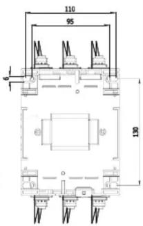
Technical Drawings
ENT-KT-33-C12, ENT-KT-40-C12, ENT-KT-75-C12, ENT-KT-50-C12 ENT-KT-60-C12
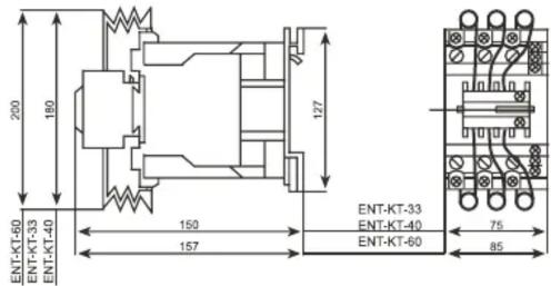
text_image
200 180 127 ENT-KT-60 ENT-KT-33 ENT-KT-40 150 157 ENT-KT-33 ENT-KT-40 ENT-KT-60 75 85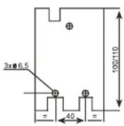
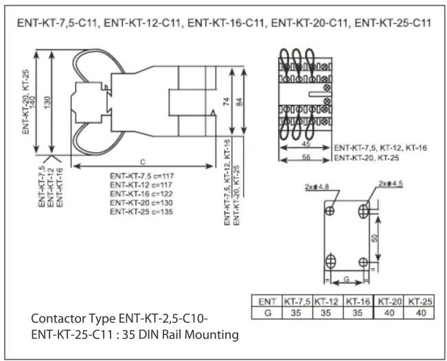
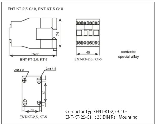
Contactor Type ENT-KT-2,5-C10-ENT-KT-25-C11:35 DIN Rail Mounting
ENT-KT-100-C12
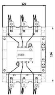
text_image
120 154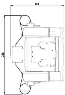
text_image
154 236