
DC10223 - Système de sécurité et de contrôle d'accès ABUS - Notice d'utilisation et mode d'emploi gratuit
Retrouvez gratuitement la notice de l'appareil DC10223 ABUS au format PDF.

| Type de produit | Ferme-porte |
| Marque | ABUS |
| Modèle | DC10223 |
| Utilisation | Portes intérieures et extérieures |
| Matériau | Acier et aluminium |
| Dimensions (L x l x h) | 195 x 50 x 65 mm |
| Poids | 1,5 kg |
| Finition | Argenté |
| Montage | Standard, haut-bas inversé, parallèle (selon modèle) |
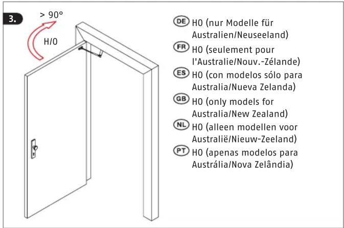
| Réglage de la force de fermeture | Oui (H0 pour modèles spécifiques) |
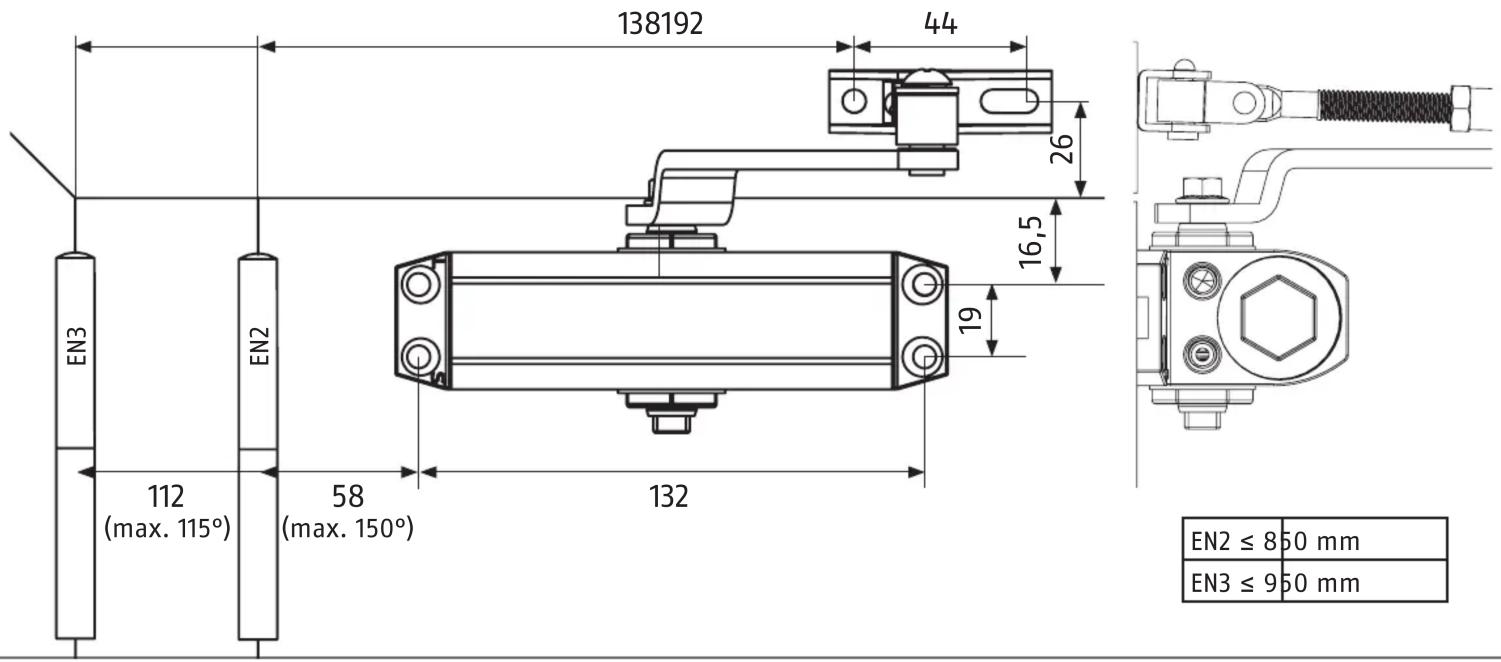
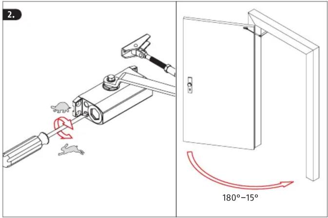
| Angle d'ouverture maximal | 150° |
| Norme EN | EN2, EN3 (selon modèle) |
| Température d'utilisation | -20°C à +60°C |
| Garantie | 2 ans |
| Entretien | Lubrification périodique des pièces mobiles |
| Sécurité | Vérifier la compatibilité avant montage |
| Contenu du pack | Ferme-porte, bras, platine, vis, notice |
| Pays d'origine | Allemagne |
FOIRE AUX QUESTIONS - DC10223 ABUS
Questions des utilisateurs sur DC10223 ABUS
0 question sur cet appareil. Repondez a celles que vous connaissez ou posez la votre.
Poser une nouvelle question sur cet appareil
Téléchargez la notice de votre Système de sécurité et de contrôle d'accès au format PDF gratuitement ! Retrouvez votre notice DC10223 - ABUS et reprennez votre appareil électronique en main. Sur cette page sont publiés tous les documents nécessaires à l'utilisation de votre appareil DC10223 de la marque ABUS.
MODE D'EMPLOI DC10223 ABUS
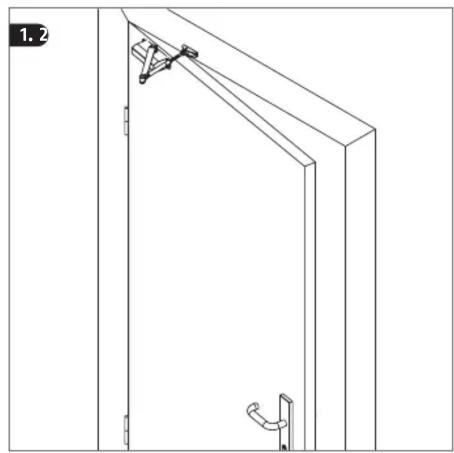
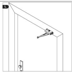
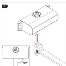
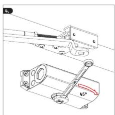
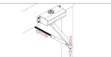
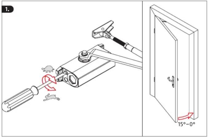
DE Standardmontage | GB Standard installation | FR Montage standard | ES Montaje estándar | PT Montagem padrão | NL Standaard montage
natural_image
Line drawing of a door frame with handle and bracket, no text or symbols present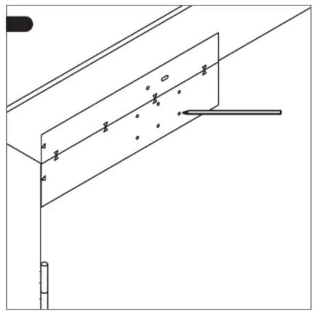
natural_image
Pure technical line drawing of a structural support frame with no text, numbers, or symbols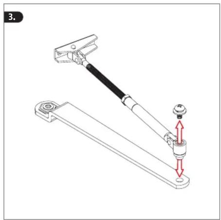
natural_image
Mechanical linkage diagram showing a lever and base assembly with red directional arrows indicating motion (no text or symbols)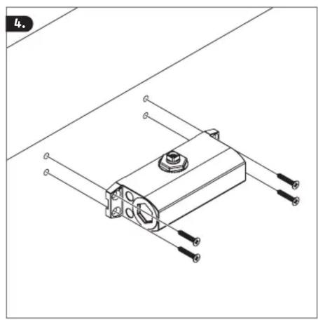
natural_image
Technical line drawing of a mechanical assembly with mounting holes and connectors (no text or symbols)
natural_image
Mechanical linkage diagram showing a lever system with two red arrows indicating motion direction (no text or symbols present)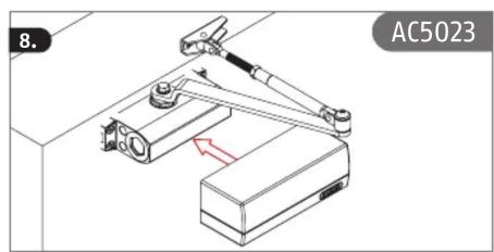
natural_image
Technical line drawing of a mechanical assembly with no visible text or symbolsDE Sturzmontage | GB Overhead installation | FR Montage haut-bas inversé | ES Montaje en la parte superior |
PT Montagem acima do nível da cabeça NL Montage boven het hoofd
DE Parallelarmmontage (nur Modelle für Australien/Neuseeland) FR Montage parallèle (seulement pour l'Australie/Nouv.-Zélande) ES Montaje con brazo paralelo (con modelos sólo para Australia/Nueva Zelanda)
GB Parallel arm installation (only models for Australia/New Zealand) NL Parallelarmmontage (alleen modellen voor Australië/Nieuw-Zeeland) PT Montagem de braços paralelos (apenas modelos para Austrália/ Nova Zelândia)
natural_image
Simple line drawing of a door frame with a handle and lock (no text or symbols)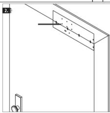
natural_image
Pure technical line drawing of a mechanical assembly without any text, numbers, or symbols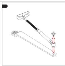
natural_image
Mechanical linkage diagram showing a lever and pivot point (no text or labels)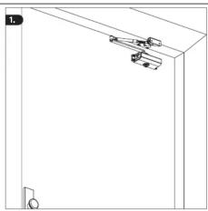
natural_image
Simple line drawing of a door frame with hanging objects (no text or symbols)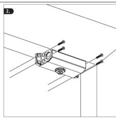
natural_image
Pure technical diagram showing a mechanical assembly with arrows indicating direction (no text or symbols)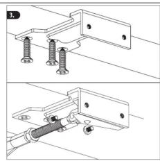
natural_image
Technical line drawing of two mechanical assembly configurations with screws and rods (no text or symbols)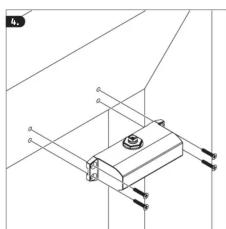
natural_image
Technical line drawing of a mechanical assembly with no visible text or symbols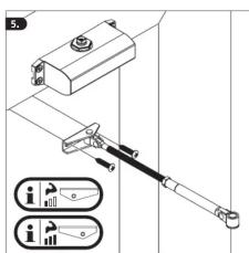
natural_image
Technical line drawing of a mechanical assembly with no visible text or symbols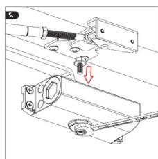
natural_image
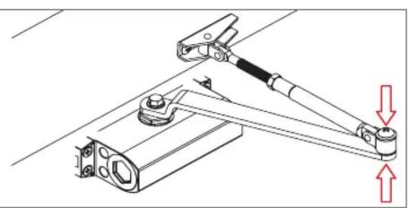
Mechanical assembly diagram showing a bracket with a g spring and a red arrow indicating a force or adjustment (no text or symbols present)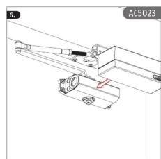
natural_image
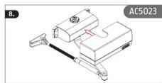
Technical line drawing of a mechanical assembly with labeled components and reference number AC5023 (no text or symbols beyond label)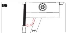
DE Allgemeine Hinweise: Vor der Montage ist sicherzustellen, dass der Türschließer für die baulichen Gegebenheiten geeignet ist. Für eventuell auftretende Verletzungen bzw. Schäden, die bei der Montage und/oder durch unsachgemäße Handhabung entstehen, übernimmt der Hersteller keine Haftung! Wir empfehlen, die Montage durch einen speziell geschulten Facherrichter ausführen zu lassen.
GB General tips: Before installation, please make sure that the door closer will work within the constructional conditions.
The manufacturer takes no responsibility for any injuries or damages that occur during installation and/or that are caused by abnormal handling! We recommend that the installation is done by a specially trained expert.
FR Consignes générales : Vérifiez avant le montage que le ferme-porte convient pour les conditions d'installation.
Le fabricant décline toute responsabilité en cas d'accident ou de dommage survenu lors du montage et/ou dû à une manipulation non conforme ! Nous conseillons de faire réaliser le montage par un installateur spécialement formé.
ES Indicaciones generales: Antes del montaje hay que asegurarse de que el cierrapuertas sea apto para las condiciones de montaje. El fabricante no se hace responsable de posibles daños o lesiones que se produzcan durante el montaje y/o por un manejo indebido. Le recomendamos encargar el montaje a una empresa especializada.
PT Instruções gerais: Antes da montagem, é necessário garantir que a mola de porta é adequada para as condições estruturais do local. O fabricante não assume quaisquer responsabilidades por eventuais ferimentos ou danos que ocorram durante a montagem e/ou resultem do uso indevido! Recomendamos que a montagem seja realizada por um técnico especializado.
NL Algemene instructies: Voorafgaand aan de montage dient u te controleren of de deurdranger geschikt is voor de bouwkundige situatie. De fabrikant aanvaardt geen verantwoordelijkheid voor eventueel letsel of schade, welke ontstaat bij de montage en/of door verkeerd gebruik! Wij raden aan de montage door een speciaal opgeleide vakman uit te laten voeren.
© ABUS 2022
ABUS August Bremicker Söhne KG | D 58292 Wetter | Germany.
Tel.: +49 (0) 23 35 63 40 | www.abus.com info@abus.de
UK-Importer: ABUS (UK) Ltd.
Unit 8 Third Way Corner, Avonmouth
Bristol BS11 9HL, UK
Tel.: +44 117 204 70 00 | info@abus-uk.com

Marque : ABUS
Modèle : DC10223
Catégorie : Système de sécurité et de contrôle d'accès