2CKA006189A0102 - Maison intelligente Busch-Jaeger - Notice d'utilisation et mode d'emploi gratuit
Retrouvez gratuitement la notice de l'appareil 2CKA006189A0102 Busch-Jaeger au format PDF.

| Type de produit | Actionneur de commutation KNX |
| Marque | Busch-Jaeger |
| Modèles | 6194/25 (2 voies), 6194/26 (4 voies), 6194/27 (8 voies), 6194/28 (12 voies) |
| Alimentation | Bus KNX (21-30 V DC) |
| Courant nominal par sortie | 16 A |
| Tension de commutation | 250/440 V AC |
| Type de contact | Potentiel libre, indépendant |
| Dimensions (L x H x P) | 2 voies : 36 x 90 x 58 mm ; 4 voies : 72 x 90 x 58 mm ; 8 voies : 144 x 90 x 58 mm ; 12 voies : 216 x 90 x 58 mm |
| Montage | Sur rail DIN 35 mm (EN 60715) |
| Indice de protection | IP20 |
| Classe de protection | II |
| Température de fonctionnement | -5°C à +45°C |
| Température de stockage | -25°C à +55°C |
| Programmation | Via logiciel ETS (Engineering Tool Software) |
| Affichage | LED rouge de programmation, indicateur de position du contact |
| Commande manuelle | Levier ON/OFF par voie |
| Nettoyage | Chiffon sec ou légèrement humide (solution savonneuse) ; ne pas utiliser de solvants |
| Sécurité | Installation par électricien qualifié ; déconnecter tous les pôles avant extension ou modification du circuit |
FOIRE AUX QUESTIONS - 2CKA006189A0102 Busch-Jaeger
Questions des utilisateurs sur 2CKA006189A0102 Busch-Jaeger
0 question sur cet appareil. Repondez a celles que vous connaissez ou posez la votre.
Poser une nouvelle question sur cet appareil
Téléchargez la notice de votre Maison intelligente au format PDF gratuitement ! Retrouvez votre notice 2CKA006189A0102 - Busch-Jaeger et reprennez votre appareil électronique en main. Sur cette page sont publiés tous les documents nécessaires à l'utilisation de votre appareil 2CKA006189A0102 de la marque Busch-Jaeger.
MODE D'EMPLOI 2CKA006189A0102 Busch-Jaeger
Montage- und Betriebsanleitung
Installation and Operating Instructions
Mode a emploi
Montage- en bedieningshandleiding
Istruzioni per l'uso
Instrucciones de montaje de servicio
Bruksanvisning för montering och drift
安装和使用说明
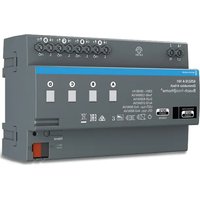
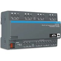
6194/25, 6194/26, 6194/27, 6194/28
DE Schaltaktor, 2-, 4-, 8-, 12-fach, 16 A
EN Switch Actuator, 2-, 4-, 8-, 12fold, 16 A
FR Module 2-, 4-, 8-, 12 sorties TOB, 16 A
ES Actuador interruptor 2-4-8-12 canales 16 A
① Rotadora interrupa, 2-4-8-12 canali, 16 A ② Terminale di uscita, 2-4-8-12 canali, 16 A
Terminalic di ascerta, 2, 4, 6, 12 canali Schakelaktor 2, 4, 8, 12-voudig 16 A
(1) Schäkerlaktor 2-, 4-, 6-, 12-voudig to A Wyjścia bignego 3, 4, 8, 12 kanak
RL Wyjscie binałne, 2-, 4-, 8-, 12 Kanalowe, 10 A
мactivator, 2-, 4-, 8-, 12-кан., 16 А
CN 开关驱动器,2-,4-,8-,12路,16 A
Busch-Installationsbus ^® KNX
2CDG 941 093 P0102
0173-1-7782 - 20.01.2016

BUSCH-JAEGER
CE
text_image
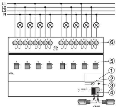
L1 L2 L3 N A B C D E F G H 6 5 ① ② ③ ④ KNY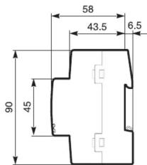
text_image
58 43.5 6.5 90 45 2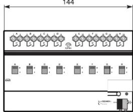
text_image
144 A: B: C: D: E: F: G: H: I: J: K: L: M: N: O: P: Q: R: S: T: U: V: W: X: Y: Z: A B C D E F G H I J K L M N O P Q R S T U V W X Y Z
| 6194/25 | 6194/26 6 | 94/27 | 6194/28 | |
| B | 36 mm2 TE | 72 mm4 TE | 144 mm8 TE | 216 mm12 TE |
| P_16A | 2 W | 4 W | 8 W | 12 W |


Geräte-Anschluss
1 Schildträger
2 Taste Programmieren
3 LED Programmieren, rot
4 Anschlussklemme KNX
5 Schaltstellungsanzeige und
EIN / AUS Betätigung
6 Laststromkreis, je 2 Schraubklemmen
Geräte-Beschreibung
Die 2-, 4-, 8- und 12-fach Schaltaktoren sind Reiheneinbaugeräte im ProM Design.
Die Schaltaktoren schalten mit 2, 4, 8, bzw. 12 potenzialfreien unabhängigen Kontakten elektrische Verbraucher (Wechsel- oder Drehstrom) über Busch Installationsbus ^® KNX oder über Schaltknebel durch Handbetätigung. Die Geräte werden über den KNX versorgt und benötigen keine zusätzliche Stromversorgung.
Technische Daten (Auszug)
Stromversorgung über Busch-Installa-
tionsbus ^® KNX
(21...30 V DC)
Anschlussklemmen Schraubklemme
0,2... 6 mm ^2 feindrähtig
0,2... 6 mm
Kabelschuh Lange Kontaktstift
min. 10 mm
Anzugsdrehmoment max. 0,6 Nm KNX Anzahlung, Bupenzahlungsklamma
KNX Anschluss Busanschlussklemme,
Verlustleistung P max. siehe Tabelle
Leistungs Ausgänge 2, 4, 8 oder 12
potentialfreie Kontakte
Schaltspannung 250/440 VAC
Nennstrom 16 A, pro Ausgang
Schaltvermögen
nach DIN EN 60947-4 16A (AC1)
Temperaturbereich
im Betrieb -5^ C ... + 45^ C
Lagerung -25°C ...
Transport -25°C ...
Schutzart IP20 nach DIN EN 60529
Schutzklasse II nach DIN EN 61140
Überspannungs-
kategorie III nach DIN EN 60664-1
Verschmutzungsgrad 2 nach DIN EN 60664-1
Luftdruck Atmosphäre bis 2.000 m
Bedienung und Anzeige

- Schalterstellungsanzeige (5)
- EIN / AUS manuelle Bedienung
Über ein Schaltknebel können
die Lastkreise manuell EIN (I)
oder AUS (0) geschaltet werden
Gleichzeitig dient der Schaltkne
bel zur Anzeige der Kontaktstel
lung geschlossen (I) geöffnet (0)
Programmier-LED (3)
leuchtet rot, wenn das Gerät im
Programmiermodus ist (Nachdem
der Programmiertaster (2)
ckt wurde).
Montage
Das Gerät ist geeignet zum Einbau in Verteilern
oder Kleingehäusen für Schnellbefestigung auf 35 mm Tragschienen, nach EN 60715.
Die Zugänglichkeit des Gerätes zum Betreiben,
Prüfen, Besichtigen, Warten und Reparieren muss sichergestellt sein.
Anschluss
Der elektrische Anschluss erfolgt über Schraub-
klemmen. Die Klemmenbezeichnungen
befinden sich auf dem Gehäuse. Die Verbindung wurde KNX erfolgt mit davon mit
Die verbindung zum KNX erfolgt mit der mitgelieferten Busanschlussklemme.
Inbetriebnahme
Die Inbetriebnahme erfolgt mit der Engineering
Tool Software (ETS). Eine ausführliche
Beschreibung der Parametrierung und Inbetriebnahme finden Sie in der technischen
Inbetriebnahme finden Sie in der technischen Dokumentation des Gerätes. Diese finden Sie
zum Download unter www.BUSCH-JAEGER.
de.

Wichtige Hinweise
Achtung! Gefährliche Spannung! Installation
nur durch elektrotechnische Fachkraft. Bei
der Planung und Errichtung von elektrischen Anlagen sind die einschlägigen Normen
Anlagen sind die einschlagigen Nornen, Richtlinien, Vorschriften und Bestimmungen
Richtlichen, Vorschriften und Bestimmungen zu beachten.
- Gerät bei Transport, Lagerung und im Betrieb
vor Feuchtigkeit, Schmutz und Beschä
gung schützen!
- Gerät nur innerhalb der spezifizierten
technischen Daten betreiben!
- Gerät nur im geschlossenen Gehäuse
(Verteiler) betreiben!
Um gefährliche Berührungsspannung durch
Rückspeisung aus unterschiedlichen Aus-
senleitern zu vermeiden, muss bei einer
Erweiterung oder Änderung des elektrischen Anschlusses eine allolige Abschaltung vorge-
Anschlusses eine allolige Abschaltung vorge- nommen werden
Reinigen
Verschmutzte Geräte können mit einem
trockenen oder leicht mit Seifenlösung ange-
feuchteten Tuch gereinigt werden. Auf keinen Fell dürfen ötzende Mittel oder Lösungsmittel
Fair durfen atzende Mittel oder Lösungsmittel verwendet werden.
Wartung
Das Gerät ist wartungsfrei. Bei Schäden z.B.
durch Transport oder Lagerung, dürfen keine Reparaturen vorgenommen werden.

Device connection 4 Label carrier
1 Label carrier 2 Programerin
2 Programming key 3 Programming LED
3 Programming LED, red 4 Connecting terminal IKN
4 Connecting terminal KN.
5 Switch position display and
ON/OFF operation
6 Load current circuit, each with 2 screw terminals
Device description
The 2, 4, 8 and 12-fold switch actuators are
modular installation devices in ProM design.
The switch actuators switch electrical
consumers with 2, 4, 8 or 12 potential-free independent contacts (single phase or three
independent contacts (single-phase of three-phase alternating current) via an Busch-
Phase alternating currently via an Busen Installationsbus ^® KNX or using manually
operated toggle switches.
The devices are supplied with power via the
KNX and do not require an additional power
sup
Technical data (excerpt)
Power supply via Busch-Installations-
bus ^® KNX
(21...30 V DC)
Connection terminals
0.2... 6 mm
^2 , fine-wire
0.2..
^2 single wire
Cable shoe
Long contact pin
10 mm min
[Non-Text]
Tightening torque
0.6 Nm max.
KNX connecto
bus terminal screwless
Power loss P
Max. see table 1
Power outputs
2, 4, 8 or 12
Floating contacts
[Non-Text]
Switch voltage 250/440 VAC
440 VAC
Rated current
16 A, per output
Switching capa
[Non-Text]
per EN 60947-
16A (AC1)
Temperature range
[Non-Text]
when operating
5^ +45^
Storage
-25°C ... + 55°C
Transport -25°C ... + 70°C
+ 70° C
IP20
in accordance with
EN 60529
[Non-Text]
Safety class
II according with
EN 61140
[Non-Text]
Overvoltage category
III, EN 60664-1 compliant
Pollution class
2, in accorda
[Non-Text]
EN 60664-1
Atmospheric pressure
Atmosphere up to 2,000 m
Operation and display

itch position display (5)
- Manual ON/OFF
The load circuits can be switched
ON (I) or OFF (0) manually via a
toggle switch. The toggle switch
is also used to display the contact
position closed (I) or open (O).

Programming LED (3)
Lights up red when the device is
operated in programming mode
(after pressing the Programming
button (2)).
Installation
The unit is designed to be installed in
distribution boxes or small housings for
quick mounting on 35 mm support rails in accordance with EN 60715.
Ensure that the unit can be accessed at all
times for operation, examination, inspection,
maintenance, and repair.
Connection
The electrical connections are made via screw
terminals. The terminal identifiers can be found on the housing.
The connection to KNX is made via the
supplied bus terminal.
Commissioning
Commissioning of the system is carried out
using the Engineering Tool Software (ETS).
A detailed description of the parameter configuration and commissioning steps can
configuration and commissioning steps can be found in the technical documentation of
be found in the technical documentation of the unit. This information can be downloaded
at www.BUSCH-JAEGER.de.

Important notes
Attention! Hazardous voltage! Installation by
person with electrotechnical expertise only.
The relevant standards, directives, regulations and instructions must be observed when
tions and instructions must be observed when planning and implementing the electrical
planning and implementing the electrical installation.
- Protect the device against moisture, dirt
and damage during transport, storage
and operation!
- Always operate the device within the speci-
fied technical data.
- The unit may only be operated in closed
enclosures (e.g. distribution boards).
In order to avoid dangerous contact voltages
that are caused by feedback from various
phase conductors, an all-pole disconnection
must be ensured prior to extending or changing the electrical connection.
ing the electrical connection.
Cleaning
Soiled units can be cleaned with a dry cloth
or with a cloth that is slightly moistened with
a soap solution. Do not use corrosive agents or solvents.
or solvents.
Maintenance
The unit is maintenance-free. Do not carry out
any repairs when the unit is damaged (e.g.
during transport, storage).
[Non-Text]
[Non-Text]
[Non-Text]
[Non-Text]
[Non-Text]
[Non-Text]
[Non-Text]
[Non-Text]
[Non-Text]
[Non-Text]
[Non-Text]
[Non-Text]
[Non-Text]
[Non-Text]
[Non-Text]
[Non-Text]
[Non-Text]
Device connection 1 Label carrier 2 Programming key 3 Programming LED, red 4 Connecting terminal KNX 5 Switch position display and ON/OFF operation 6 Load current circuit, each with 2 screw terminals
Device description The 2, 4, 8 and 12-fold switch actuators are modular installation devices in ProM design. The switch actuators switch electrical consumers with 2, 4, 8 or 12 potential-free independent contacts (single-phase or three-phase alternating current) via an Busch-Installationsbus® KNX or using manually operated toggle switches. The devices are supplied with power via the KNX and do not require an additional power supply.
Technical data (excerpt) Power supply via Busch-Installations-bus® KNX (21...30 V DC) Connection terminals screw terminal 0.2...6 mm 0.2...6 mm Cable shoe Long contact pin 10 mm min. Tightening torque 0.6 Nm max. KNX connector bus terminal screwless Power loss P Max. see table [1] Power outputs 2, 4, 8 or 12 Floating contacts Switch voltage 250/440 VAC Rated current 16 A, per output Switching capacity as per EN 60947-4 16A (AC1) Temperature range when operating -5°C ... +45°C Storage -25°C ... +55°C Transport -25°C ... +70°C IP20 in accordance with EN 60529 Safety class II according with EN 61140 Overvoltage category III, EN 60664-1 compliant Pollution class 2, in accordance with EN 60664-1 Atmospheric pressure Atmosphere up to 2,000 m
Operation and display - Switch position display (5) - Manual ON/OFF The load circuits can be switched ON (I) or OFF (O) manually via a toggle switch. The toggle switch is also used to display the contact position closed (I) or open (O).
Programming LED (3) Lights up red when the device is operated in programming mode (after pressing the Programming button (2)).
Installation The unit is designed to be installed in distribution boxes or small housings for quick mounting on 35 mm support rails in accordance with EN 60715. Ensure that the unit can be accessed at all times for operation, examination, inspection, maintenance, and repair.
Connection The electrical connections are made via screw terminals. The terminal identifiers can be found on the housing. The connection to KNX is made via the supplied bus terminal.
Commissioning Commissioning of the system is carried out using the Engineering Tool Software (ETS). A detailed description of the parameter configuration and commissioning steps can be found in the technical documentation of the unit. This information can be downloaded at www.BUSCH-JAEGER.de.
Important notes Attention! Hazardous voltage! Installation by person with electrotechnical expertise only. The relevant standards, directives, regulations and instructions must be observed when planning and implementing the electrical installation. - Protect the device against moisture, dirt and damage during transport, storage and operation! - Always operate the device within the specified technical data. - The unit may only be operated in closed enclosures (e.g. distribution boards).
Cleaning Soiled units can be cleaned with a dry cloth or with a cloth that is slightly moistened with a soap solution. Do not use corrosive agents or solvents.
Maintenance The unit is maintenance-free. Do not carry out any repairs when the unit is damaged (e.g. during transport, storage).
[Non-Text]
[Non-Text]
[Non-Text]
(2)
Device connection EN
1 Label carrier
2 Programming key
3 Programming LED, red
4 Connecting terminal KNX
5 Switch position display and ON/OFF operation
6 Load current circuit, each with 2 screw
terminals
[Non-Text]
Device description
The 2, 4, 8 and 12-fold switch actuators are
modular installation devices in Prom design. The switch actuators switch electrical
The switch actuators switch electrical consumers with 2, 4, 8 or 12 potential-free
independent contacts (single-phase or three-
phase alternating current) via an Busch-
Installationsbus ^® KNX or using manually
operated toggle switches.
The devices are supplied with power via the KNY and do not require an additional power
Collegamento dell'apparecchio
1 Portatarghetta
2 Tasto Programmazione
3 LED di programmazione, rosso
4 Morsetto KNX
5 Indicatore di posizione e
azionamento ON / OFF 6. Circuito di azione, risso, nel 2 marmatti e vite
6 Circuito di carico, risp. per 2 morsetti a vite
Descrizione dell'apparecchio
Gli attuatori a 2, 4, 8 e 12 poli sono apparecchi
da incasso in serie con design ProM.
Gli attuatori attivano le utenze elettriche
(corrente alternata o trifase) con 2, 4, 8 o
12 contatti indipendenti a potenziale zero attraverso Busch Installationsbus® KNX
attraverso Busch-installationsbus KNX oppure attraverso nettele ad azionements
oppure attraverso nottole ad azionamento manuale.
Gli apparecchi vengono alimentati da KNX
e non richiedono un'alimentazione elettrica
esterr
(1)
Aansluiting van het apparaat
1 Bevestiging voor plaatje
2 Toets "Programmeren"
3 LED "Programmeren", rood
4 Aansluitklem KNX
5 Schakelstandindicatie en AAN/UIT schakelen
6 Laststroomkring, telkens 2 schroefklemmen
Beschrijving van het apparaat
De 2-, 4-, 8- en 12-voudige schakelactoren zijn apparaten voor de seriële montage in het ProM design.
De schakelactoren schakelen elektrische ver-
bruikers (wissel- of draaistroom) met 2, 4, 8,
of 12 potentiaalvrije contacten via de Busch-
Installationsbus® KNX of handmatig via de
schakelknop. De gevoersten worden via de KNX van stroom
De apparaten worden via de KNX van stroom voorzien, zedet geen extra stroomvoorzie
voorzien, zodat geen extra stroomvoorziening noodzakelijk is.
NE
Przyłącze urządzenia
1 Podstawa tabliczki
2 Przycisk programowania
3 LED programowania, czerwona
4 Zacisk przyłączeniowy KNX
5 Wskazanie połączenia łączeniowego
i uruchomienie WŁ./WYŁ
6 Obwód prądu obciążenia, po 2 zaciski
śrubowe
TE
1 Крепление таблички
2 Кнопка программирования
3 Программируемый светодиод, красный
4 Присоединительный зажим KNX
5 Индикатор положения переключения и
переключатель ВКЛ/ВЫКЛ
zaciski 6 Силовая цепь, по 2 винтовых зажима
No
1 Крепление таблички
2 Кнопка программирования
3 Программируемый светодиод, красный
4 Присоединительный зажим KNX
5 Индикатор положения переключения и
переключатель ВКЛ/ВЫКЛ
6 Силовая цепь, по 2 винтовых зажима
Описание устройства
2-, 4-, 8- и 12-контактные приводы переключателя
представляют собой последовательные
встраиваемые приборы, выполненные в ProM
Design
Приводы переключателя с 2, 4, 8 или 12
независимыми контактами с нулевым
потенциалом обеспечивают включение
электрических потребителей (переменный или
трехфазный ток) через Busch-Installationsbus®
KNX или ручку переключателя вручную.
Питание подается на устройства через KNX,
поэтому потребность в дополнительном
электроснабжении отсутствует.
(2.1)
1 铭牌托
2 编程按钮
3 编程 LED
4 接线端子
5 开关位置
开 / 关操作装置
- 负载电路,每 2 个螺旋接线端子
设备描述
2/4/8/12 路开关致动器是采用 PROM 设计的系列安
装设备。
这款开关致动器通过手动操作Busch-Installationsbus®
KNX 或开关旋钮,借助独立的 2/4/8/12 路无电势触点
接通/断开用电器(交流电或三相电流)
设备均通过KNX供电,无需额外电源供应。
Dati tecnici (estratto)
Alimentazione elettrica tramiteBusch-Installa-
tionsbus ^® KNX
(21...30 V DC)
Morsetto a vite
0,2... 6 mm² conduttore
flessibile
0,2... 6 mm² conduttore
rigido
Terminale cavo Lunghezza spina a contatto
min. 10 mm
max. 0,6 Nm
Collegamento KNX Morsetto di collegamen-
senza viti
Potenza dissipata P Max. vedere tabella 11
2, 4, 8 o 12
contatti a potenziale zero
Tensione di
commutazione 250/440 V AC
Corrente nominale 16 A, per uscita
Potere di interruzione
a norma EN 60947-4 16A (AC1)
Intervallo di temperatura
durante il funzionamento -5°C ... + 45 °C
Technische gegevens (uittreksel)
Stroomvoorziening via Busch-Installations-
bus ^® KNX
(21...30 V DC)
Aansluitklemmen Schroefklemmen
0,2... 6 mm ^2 fijne draad
0,2... 6 mm² enkele
draad
Kabelschoen Lengte contactpen
[Non-Text]
Aanhaalmoment max. 0,6 Nm
saansluitklem.
schroefloos
Vermogensverlies P Max. zie tabel 1
Vermogens uitgangen 2, 4, 8 of 12
potentiaalvrije contacten
schakelspanning 250/440 VAC
Nominale stroom 16 A. per uitgand
schakelvermogen
Conform EN 60947-4 16A (AC1)
,
in bedrijf -5°C ... + 45°C
-25°C ... + 55°C
Transport -25°C ... +70°C
Dane techniczne (wyciąg)
Zasilanieprzezmagistrale
Busch-Installations-
bus ^® KNX
(21...30 V DC)
Zaciski przyłączeniowe zaciski śrubowe
0,2... 6 mm² cienkodrutowe
0,2... 6 mm² jednodrutowe
Końcówka kablowa długość bolca styku
min. 10 mm
Moment dokręcania maks. 0,6 Nm
sk przyłączeniowy
magistrali, bezśru
Strata mocy Maks. patrz tabela 1
Wyjścia robocze 2, 4, 8 lub 12
styki bezpotencjałowe
Napiecie łączeniowe 250/440 V AC
Prad znamionowy 16 A. na wyiście
Zdolność przełączania
według EN 60947-4 16A (AC1)
Zakres temperatury
podczas pracy -5 °C ... + 45 °C
składowanie -25 °C ... + 55 °C
transport -25 °C ... + 70 °C
Технические характеристики (фрагмент)
Электропитание через Busch-
Installationsbus
(21 – 30 В пост. тока)
Присоединительные
зажимы Винтовой зажим
0,2 - 6 MM
многожильный 0,2 – 6 мм² одножильный
Кабельный наконечник Длина контактного стержня
мин. 10 мм
Момент затяжки макс. 0,6 Нм
Зажим KNX Шинная клемма.
безвинт.
Мощность потерь Р Макс. см. в таблице
Силовые выходы 2,4,8 или 12
контактов с нулевым
потенциалом
Переключающее
напряжение 250/440 В перем. тока
Номинальный ток 16 А, на выход
Коммутационная способность
в соотв. с EN 60947-4 16A (AC1)
Температурный диапазон
во время эксплуатации от -5° C до + 45° C
при хранении от -25° С до + 55° С
技术参数(摘录)
电源 通过Busch-Installationsbus*
KNX 供应 (21...30 V DC)
接线端子 螺旋接线端子
0.2...6mm2细电缆
0.2... 6 mm2 单线
电缆接头套管
接触销长度
至少 10mm
紧固扭矩 最大 0.6 Nm
[Non-Text]
KNX接口 总线接线端子,
无螺丝
功率损耗
最大值参见表
功率输出 2/4/8/12 路
(No text)
[Non-Text]
无电势触点
开关电压 250/440 VAC
额定电流 每个输出端16
开关电容
[Non-Text]
按照 EN 60947-4 16A (AC1)
温度范围
[Non-Text]
运行时 -5^ +45^
存放 -25^ C ... + 55^ C
C
运输 -25^ +70^
C
防护类型 IP20,按照 EN 60529
61140
[Non-Text]
过电压
类别 III,按照 EN 60664-
污染程度 2,按照 EN 60664-1
空气压力 2000 m以下的大气压
Immagazz
-25°C ... + 55 °C
-25°C ... + 70 °C
Tipo di protezione IP2 0 a norma EN 60529
Classe di protezione Il a norma EN 61140
Categoria di
sovratensione III a norma EN 60664-1
Grado di inquinamento 2 a norma EN 60 60664-1
Pressione aria Atmosfera fino a 2.000 m
Comando e visualizzazione
- Indicatore dello stato operativo (5)
omando manuale ON / OFF
Con una nottola si possono
attivare (I) e disattivare (0) ma-
nualmente i circuiti di carico. La
nottola svolge anche la funzione
di visualizzazione di contatto chiu-
so (l) e di contatto aperto (0).
LED
ammazione (3)
è acceso in rosso, quando
l'apparecchio si trova in modalità
di programmazione (dopo aver
premuto il tasto di programma-
zione (2)
Montaggio
L'apparecchio può essere montato in distributori
o in piccoli quadri elettrici per il fissaggio rapido
su guide di montaggio da 35 mm a norme EN 60715.
Deve essere assicurata l'accessibilità
all'apparecchio a scopo di controllo, ispezione,
manutenzione e riparazione.
Collegamento
Il collegamento elettrico viene eseguito
mediante morsetti a vite. Le sigle dei morsetti
sono riportate sulla scatola dell'apparecchio.
Il collegamento ai KNX viene realizzato con il morsetto di collegamento del bus in dotazione.
Messa in servizio
La messa in servizio viene eseguita mediante
I'Engineering Tool Software (ETS). Per la
descrizione dettagliata della parametrizzazione
e della messa in servizio consultare la documentazioni tecnico dell'operaeschie
documentazione tecnica dell'apparecchio scaricabile dal sito www.BUSCH-JAEGER.de
Beschermingstype IP20 conform EN 60529
Beschermingsklasse II conform EN 61140
Overspannings
categorie III conform EN 60664-1
Verontreinigingsgraad 2 conform EN 60664-1
Luchtdruk Atmosfeer tot 2.000 m
Bediening en weergave
0
- Schakelaarstandindicatie (5)
- Handmatige AAN/UIT bediening
Via een schakelknop kunnen de
lastkringen handmatig AAN (I) of
UIT (0) geschakeld worden. Ge-
lijktijdig dient de schakelknop als
weergave van de contactstanden
"gesloten" (I) en "geopend" (0)
The image is too blurry to recognize any text content.
Programmeer-LED (3)
brandt rood, wanneer het apparaat
in de programmeermodus staat
(nadat de programmeertoets (2) is
ingedrukt).
Stopień ochrony IP20 wg DIN EN 60529
Klasa ochrony II wg EN 61140
Kategoria
przepięciowa III wg EN 60664-1
Stopień zabrudzenia 2 według EN 60664-1
Ciśnienie powietrza Atmosfera do 2 000 m
(No text)
- Wskazanie stanu przełącznika (5)
D. 100%
- Ręczna obsługa WŁ./WYŁ.
Za pomoca przełącznika można
La pomocą przolgelnika można recznie włącać (I) lub wyłącać
(0) obwody robocze. Bównocze-
(6) obwoy robosze: Nownozośnie przełącznik stanowi wskaza-
nie stanu styku: zwarty (i) rozwarty
(Ⅲ)
(ii)
The image is too blurry to recognize any text content.