JA50W - Caméra de surveillance Jablotron - Notice d'utilisation et mode d'emploi gratuit
Retrouvez gratuitement la notice de l'appareil JA50W Jablotron au format PDF.


| Type de produit | Caméra de surveillance sans fil (système d'alarme) |
| Marque | Joblotron |
| Modèle | JA50W |
| Alimentation secteur | 220 V / 50 Hz (110 V / 60 Hz) |
| Batterie de secours | 12 V / 1,2 Ah (rechargeable) |
| Zones de détection | 4 zones : retard, instantanée, 24h, feu |
| Sirène intégrée | 120 dB à 1 m |
| Sortie sirène externe | 12 V / 1 A |
| Portée détecteur - panneau | 60 m (champ libre) |
| Alimentation des détecteurs | Pile 9 V (alcaline recommandée) |
| Retard d'entrée/sortie | Programmable de 10 s à 5 min (défaut 20 s) |
| Durée d'alarme | Programmable de 10 s à 5 min (défaut 5 min) |
| Sortie relais d'alarme | Contact sec 1 A / 60 V max |
| Mémoire des codes | EEPROM non volatile |
| Entretien et nettoyage | Essuyer avec un chiffon doux et sec. Ne pas utiliser de solvants. |
| Sécurité | Utiliser uniquement des piles alcalines de haute qualité. Respecter les polarités. |
| Pièces détachées et réparabilité | Piles 9 V et batterie de secours 12 V remplaçables. Pour autres pièces, contacter le SAV. |
| Informations générales | Système d'alarme sans fil avec détecteurs de mouvement, télécommande et panneau de contrôle. |
FOIRE AUX QUESTIONS - JA50W Jablotron
Questions des utilisateurs sur JA50W Jablotron
0 question sur cet appareil. Repondez a celles que vous connaissez ou posez la votre.
Poser une nouvelle question sur cet appareil
Téléchargez la notice de votre Caméra de surveillance au format PDF gratuitement ! Retrouvez votre notice JA50W - Jablotron et reprennez votre appareil électronique en main. Sur cette page sont publiés tous les documents nécessaires à l'utilisation de votre appareil JA50W de la marque Jablotron.
MODE D'EMPLOI JA50W Jablotron
WIRELESS ALARM SYSTEM
JA-50
installation manual
ver. 1.4.

contents:
I. BASIC INSTALLATION
- Before starting
- Required tools
- Installation of control panel
3.1. Opening of control panel
3.2. Fixing of control panel on the wall
3.3. Connecting of A.C. adapter
3.4. Back up battery installation
- Installation of detectors
4.1. Preparation of detectors
4.2. Location of motion detectors
4.3. Motion detectors installation
4.4. Determination of detectors to zones
4.5. Walking test of JA-50P detector
- Testing of complete system JA-50W
II. ADVANCED CUSTOMER MODIFICATION OF THE SYSTEM
- Detector setting
6.1. Detector's HOUSE CODE
6.2. Setting of a new HOUSE CODE in detectors
6.3. The other DIP switches in detectors
- Control panel setting
7.1 Control code setting (remote control or digital keypad)
7.2. Control panel HOUSE CODE setting
7.3. Setting of EXIT/ENTRY delay
7.4. Setting of alarm duration
7.5. Loudness of arming confirmation, pre-alarm sound
7.6. Switching off the built in siren
- System extension
8.1. More detectors
8.2. More remote controls or digital keypads
8.3. Terminals of JA-50K control panel
- Wiring of optional devices
9.1. Pre-alarm buzzer
9.2. External siren
9.3. Outdoor siren OS-200
9.4. Telephone dialer TD-100
- Important Warning
- Specifications
I. Basic installation
1. Before starting
Read this manual and attached JA-50 catalog sheet before attempting installation. If you have any questions or do not understand any steps, contact your supplier.
2. Required tools
Before installation, you should be sure to have the following tools and equipment: An assortment of screwdrivers, a pencil, a drill with an assortment of bits. You should also prepare a 9V battery for each detector. We recommend that you use only high quality alkaline batteries.
3. Installation of control panel
The Control panel should be fixed to a wall using the two screws (provided in the kit). We recommend that you use the plastic screw setting devices supplied if you are setting the screws into a hard material wall.
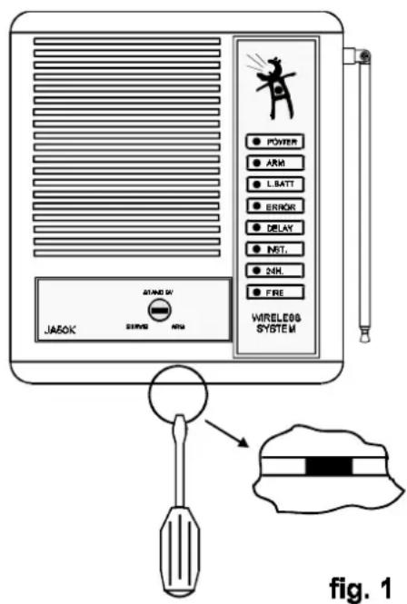

fig. 2
3.1. Opening of control panel
Open the front panel by pressing the lock located on the bottom of the JA-50K. Place a narrow screwdriver into the small slot and press the plastic tab inside (see fig.1). While pushing down the small tab, pull the bottom of the front panel away from the rear panel. Do not great force. Remove the panel slowly to insure that the two cables connecting the front and back panel are not damaged.
After the panel is open, disconnect the cables from the back panel by pulling the connectors from the rear board. It is O.K. to hold the wires while pulling.
3.2. Fixing of control panel on the wall
Find a suitable location for the control panel. Be sure that the surface of the wall is level. Avoid placing the panel in a location that will result in the antenna being near any large metal objects. Doing so may interfere in your unit's reception.
There are two slots for screws on the back side of the rear panel (see fig.2). Once you have the panel in the desired location, use the pencil to mark on the wall the spot of the top screw.
To mount the panel, first partially screw in the top screw, leaving part of the head sticking out. Slide the screw head through the small round hole in the upper half of the back side of the rear panel.
Once the screw is in, slide the plastic housing down so that so slides to the middle of the slot. Now mark the position of the lo screw and again take down the rear panel.
Make a hole in the wall for the second screw. Also, place the cable from the A.C. adapter through the hole for cables in the rear panel. If you are installing any optional device, such as a telephone dialer, you want to place its cable through this hole also. Refer to figure 2 again if you can not locate the hole for the cables.
Confirm one more time that the surface of the wall is level and that the location is your desired spot for the control panel. Now replace the rear panel on the wall and screw in the top and bottom screws tightly.
3.3.Connection of A.C. adapter
Connect the A.C. adapter jack to the "POWER" connector on the control panel's board. It is located on the bottom left hand corner and is marked in figure two. Plug in the A.C. adapter to the A.C. power supply for a moment (the control panel is still without the front part). If adapter has been connected properly, the green LED (Light Emitting Diode) on the board should light up and a buzzer will sound for a short while.
Unplug A.C. adapter again!
Note: If you install any optional devices - (telephone dialer etc.) make sure their wiring is installed at this moment. See chapter 9.

fig. 3
3.4. Back up battery installation
Remove the protection folio from the fixing tape which is located in the battery compartment (see fig.2).
Be sure to only use a Jablotron branded battery size 12V 1.2Ah (which comes with your system).
WARNING - Do not make any short connection of battery terminals under any circumstance!
To connect the battery, first locate the two wires with fast-on connectors (red & black) on the rear panel. Slide the black connector over the black colored terminal on your battery (negative one).
Then place the battery to the battery compartment. The black terminal must be inside the housing (see fig.3). Attach the battery to the tape inside the housing.
Now connect the red wire to the battery's red terminal (positive pole) for a moment. If the battery is ready the buzzer will sound for a while. Disconnect the red wire again after this test!
NOTE: The control panel charges the battery automatically. The battery can provide over 48 hours of operating electricity for the control panel when there is a failure of the A.C. power. Before the battery is discharged completely, the control panel will trigger a "Technical Alarm" to call for help.
4. Installation of detectors

fig. 4
4.1. Preparation of detectors
There are two motion detectors (JA-50P) and one remote control (JA-50C) in each standard JA-50W set.
Open the front cover of each motion detector (see fig.4). Install 9V battery to each detector (leave them open).
Plug the A.C. adapter into the A.C. power source (control panel is still without the front cover). Buzzer will confirm it by sounding.
Press the remote control button for a moment. The buzzer in the control panel should confirm this with one beep, signifying the control code is o.k.
Press the tamper switch in one of the detectors and hold it for about 3 seconds. Then release it and control panel should answer with one beep. Check all detectors the same way.
If this test was successful, unplug the A.C. adapter and disconnect batteries from the detectors.
NOTE: If the control panel doesn't work as described above or if you bought more detectors or remote controllers which were not set for your system by distributor, see chapter 7.
4.2. Location of motion detectors
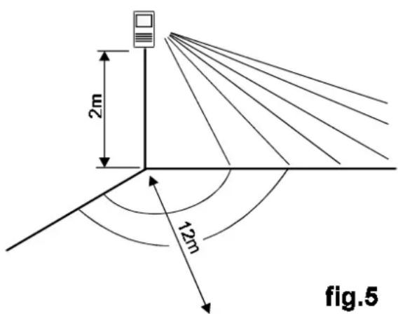
The JA-50P indoor motion detector detects human body movement within a 12 meter distance. We recommend to mount the detector in the corner of a room, 2 meters above the floor (see fig. 5).
Consider, that this detector is also sensitive to animal body movement (dogs, cats, etc.).
If you install the detector to the place, which is more problematic (frequent changes of temperature, high RF noise etc.), set the NORMAL/TEST DIP switch to TEST position (detector will test the signal twice, reaction will be a bit slower, but its immunity will be much higher).
Do not install the detector near heating devices or so sunlight can shine directly into the lens (fig. 6).
The detector must have a direct view of the room (there must not be any curtains or glass in front of it).
Large metal objects near the detector can also be an obstacle for detector communication with the control panel.

4.3. Motion detectors installation
Unscrew the Printed Circuit Board (PCB) from the rear part of opened detector housing. To do this, remove the one screw that is shown in figure 4.
Remove the punch out screw holes for mounting on the housing (one hole on the top and the second one on the bottom).
We suggest that you use a screw driver or some other sharp device.
Be careful not to place your hand on the opposite side of the hole that will be punched.
Screw the housing in the desired location (the arrow inside the housing should point up).
Install the PCB back into the housing (battery holder down).
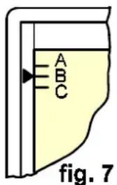
Adjust the position of PCB in the housing in such a way that the small arrow on the left side of the plastic housing will point to the "B" on the scale printed on the top left corner of PCB (see fig.7).
4.4. Determination of detectors to zones
You can select which of the control panel's zones will be triggered after a detector's activation. There is a miniature DIP switch marked INST/DEL in each JA-50P detector.
When you set this switch to INST position (upward), the detector will trigger the INSTANT zone of the control panel. This means that an alarm starts immediately after such a detector was triggered (when the control panel is in the "ARM" position). Use this setting for detectors inside the house.
If the switch is in "DEL" position (down), the detector triggers the DELAY zone of the control panel. This zone provides for an exit and entrance delay (see users manual). Use this setting for detectors which are close to the main entrance door of the house.
You can set as many detectors to each zone as you want. The tamper switch signal is always sent to 24Hr zone. The 24 hour zone will trigger an alarm immediately, regardless if the control panel is in the "Arm" or "Home" setting.
4.5. Walking test of JA-50P detector
Testing
Install a 9V battery (Jablotron recommends that you use only high quality alkaline batteries). Close the housing of detector (lens upward). Wait 1 minute for the detector to warm-up. Test how the detector covers the room by walking across the room.
The built-in LED indicates the sensor's function. If you continue to walk, the LED will remain light continuously for a while. It indicates that the detector was triggered and the corresponding signal was transmitted to the control panel. At the same moment the control panel will beep and a corresponding LED on it will flash to show which zone was triggered.
Warning: the detector has a built-in energy saving function, which is activated automatically 10 minutes after closing of the detector housing. After this period the LED is switched off completely and the signal from the detector can be transmitted to the control panel only if 5 minutes elapsed from the previous transmission as a minimum. If you need a longer period for detector testing, simply open and close the housing again (you will get next 10 minutes of testing period).


fig.8
If the detector does not cover the room properly (looks too high or too low), you can adjust its detection range. This is usually only necessary when the detector was not installed 2m above the floor. Open the detector housing and loosen the screw in the middle of the PCB a bit. By sliding the PCB up or down in its housing the area coverage can be modified (see fig. 8). If you change the position of the PCB, close the housing and perform test again. Once you have the PCB in the desired position, tighten the screw. Leave the battery installed in detector and replace the cover, being sure that the Lens is towards the top.
Test each installed detector the same way as above. If you also install other detectors (JA-50T, JA-50S) see the individual manuals that come with each detector for instructions on installation.
5. Testing of complete system JA-50W
Prepare the front panel of control panel. Use the provided system clock that the lock front panel is switched to the SERVICE position (all the way counter-clockwise).
Connect both the cables to the corresponding connectors on the PCB. The built in plastic guides will prevent you from connecting the cables upside down. You may need to push firmly to make the connector completely slide together.
Connect the red wire of the backup battery (confirmed by buzzer sounding).
To close the control panel housing, put the top side of the front panel over the back panel and then push the bottom side of the front panel against the wall gently (the tab will click).
Plug in the A.C. adapter to the power supply and check the control panel display. The POWER LED and ERROR LED should light permanently, indicating that the central unit is in "Service Mode".
You can check the communication with all of the detectors now (each must have battery connected). At first open and close again the detector housing to test tamper switch function. Control panel will respond with a beep sound and a flash of 24h LED. Then you can perform a walking test of JA-50 PIR movement detectors (see item 4.5). The corresponding zone LED and beep sound on the control panel will confirm detector triggering.
If the other JA-50 detectors were installed (JA-50T, JA-50S) follow their instructions for testing.
Test also the remote control by pressing its button. When you do this, the control panel should beep and the "ARM" LED should flash. If all detectors work properly, your system is now ready to be put into operation.
Use the key to switch the control panel to the "STAND BY" position. Two beeps will confirm that the control panel is ready and the ERROR LED should turn off.
This is the end of basic installation procedure.
NOTE: If there is any trouble with detector or remote control communication, check setting of codes (see chapter 6.1). If you want to modify some function of your system or to add some more detectors or other accessories, you will find all details in the second part of this manual.
II. ADVANCED CUSTOMER MODIFICATION OF THE SYSTEM
Your system was adjusted at the factory for you to install it with ease. But you can also simply modify some functions, or extend your system when you want to.
6. Detector setting
6.1. Detector's HOUSE CODE
There are 8 DIP switches marked HOUSE CODE in each detector (see fig.4). This code protects your system from triggering a false alarm when your neighbor install the same device. All the detectors in your system must have the same HOUSE CODE.
In the case that you buy some new detectors or you want to change your own HOUSE CODE proceed according the following description.
6.2. Setting of a new HOUSE CODE in detectors
Open the detector. At this point, you must randomly select a new code. We suggest that you use a coin and throw the coin to the air having pre-decided which side of the coin will represent "ON" and which side will represent "OFF". Use this procedure eight times to randomly set the eight switches to an "ON" or "OFF" position.
Once you have selected a new code, copy this code for all the other detectors. Remember that you also have to set the new house code on the control panel once you have changed it in the detectors (see chapter 7).
6.3. The other DIP switches in detectors
The JA-50P motion detector and the JA-50T universal transmitter are equipped with the following other DIP switches:
NORMAL/TEST (JA-50P) - The built-in sensor detects any movement of subjects which temperature which is close to human body temperature. The signal from the sensor is converted to the digital form and analyzed by a special software. This software checks, if the signal has a form which is characteristic for a human body movement. This way the false alarms can be eliminated. The longer time for analyze is provided to the microcontroller, the more exact result it can make. This time can be adjusted NORMAL/TEST miniature DIP switch. If you install the detector to the place, which is more problematic (frequent changes of temperature, high RF noise etc.), set th switch to TEST position (it will test the signal twice, reaction will be a bit slower but its immunity will higher).
INST/DEL - this switch determines which control panel's zone will be activated after the detector triggering (see chapter 4.4).
FIRE (JA-50T only) - if you set this switch to the "ON" position (upward), triggering of the INP terminal will activate the "FIRE" zone on the control panel. This is regardless of what setting the "INST/DEL" switch is on..
Triggering of the 24H terminal or the tamper switch will always result in a signal being sent to the 24Hr. control panel zone.
JA-50S - smoke detector has only HOUSE CODE switches and a testing button. Press this button and hold it for a moment to test the fire alarm zone. Be sure that you first switch the control panel to the "SERVICE" mode in order to prevent an alarm from sounding.
NOTE: You will find more details about all detectors in the individual manuals that come with each detector.
7. Control panel setting
Switch the control panel to the "SERVICE them open the front panel and disconnect the front panel" cables from the PCB. The A.C. adapter should remain plugged in and the back up battery should remain connected as well.
7.1 Control code setting (remote control or digital keypad)
The JA-50K control panel can be controlled by up to ten controllers with different codes, and an unlimited number of controllers with the same code. Each control panel comes equipped with one remote control from factory. But, it is very easy to add more remote controls or digital keypads.
The JA-50D keypad is especially suitable in the case that many people will operate the alarm system. From the point of view of communication, the keypad is similar to the remote control JA-50C. The major difference is that you can program your own communication code on the keypad. So it means that you can set the same code to an unlimited number of keypads. This results in your being able to add as many JA-50D keypads to your system as you desire.
Setting procedure:
Prepare all remote controls (max. 10) which will be used to communicate with the control panel. If you also install a digital keypad, place a 9V battery in it and check that it reacts to entering of access code (CODE OK LED). The tamper switch on the back side of the keypad must be pressed down at all times during the setting. Note that if you use a keypad, it will take the place of one of the remote controllers. So, you may use 10 controllers, or nine controllers and an unlimited number of keypads. If you desire to use more than 10 controllers, contact your dealer for help in obtaining a controller with the same code as your current controller.
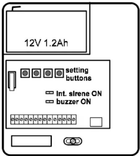
Press the button marked "LEARN CODE" inside the control panel (see fig.9) for a moment. The control panel buzzer will sound continuously, confirming that you have entered the "learning mode". Press the button of one remote control for about 1 second. The control panel confirms the code learning with a pause in the buzzer sound. When the buzzer starts to sound again, press the button on the next remote control and so on. Remember that you can teach your control panel only 10 different codes (nine controllers and keypad or ten controllers). If you attempt to teach an eleven code, the first code you taught will be erased and so on.
If you need to teach a JA-50D keypad code to the main unit, simply enter your access code. It will work the same way as if you pressed the next remote control button.
To leave the "LEARN CODE" modepress the "LEARN CODE" button inside the control panel and the control panel will "twitter" to confirm the leaving of "LEARN CODE" mode. You can check the function of all controllers now. Press a remote control button (or enter access code) and the control panel should confirm reception of the valid code by beeping.
fig. 9
NOTE: If you activated only one remote control or keypad during "learning mode", you can operate the control panel only with this one controller or keypad. All the previous control codes are forgotten. If you activate one remote control during "learning mode" two or more times, nothing will happen: the control panel can recognize that it has learned this code before and it will ignore it.
One remote control can be even taught to more control panels. So you can operate an JA-50 alarm system in your home and the second JA-50 alarm system in your office by the same remote control for example.
You can set the controller and keypad codes any time you desire. These codes are stored into the non-voltage memory, so the control panel will remember them even if the power or back up battery is disconnected.
7.2. Control panel HOUSE CODE setting
The control panel uses an extra code (HOUSE CODE) to communicate with all detectors. All detectors must have the same code (see chapter 6.2).
If you set a new HOUSE CODE in the detectors, you must teach the control panel this code.
Setting procedure:
Prepare one JA-50P (or JA-50T) with the new HOUSE CODE. Open the detector, connect the battery and leave it open.
Press the button LEARN CODE in the control panel (see fig.9) for a moment. The control panel buzzer will sound continuously, representing that you have entered "learning mode".
Activate the detector you have prepared by pressing the detector tamper switch (Refer to fig. 4), and hold it down for about 3 seconds before releasing it. The LED in the detector will flash and the control panel will confirm learning the HOUSE CODE by a pause in the buzzer sound.
Press the LEARN CODE button in the control panel again to exit the "learning mode" The control panel will "twitter" for confirmation.
You can check function of all installed detectors now. Press each detector tamper switch and hold it down for about 3 seconds before releasing. The control panel should confirm reception of the signal by beeping if HOUSE code is correct.
NOTE: The HOUSE CODE is stored in the non voltage memory.
7.3. Setting of EXIT/ENTRY delay
The duration of the E/E (Exit/Entry) delay is programmable. To set the duration of this delay, push the E/E button in the control panel once (see fig. 9). The built in buzzer will emit one or more "beeps". Each beep represents 10 seconds. So, if the buzzer beeps two times after you pushed the E/E button, then the exit/entry delay is set for 20 seconds.
If you would like to change the set duration of the exit/entry delay, first push and hold down the SET button. While holding down this button, push the E/E button. Each time you push the E/E button, the set duration will increase by 10 seconds. If you push it once, the set duration will be 10 seconds, regardless of the previous setting. The maximum setting is for 320 seconds.
To check your setting, push the E/E button once while not holding down the SET button. The number of "beeps" will confirm the current setting.
The setting is stored in the non-voltage memory.
7.4. Setting of alarm duration
The ALARM duration is programmable. To set the ALARM duration, push once the button marked ALARM in the control panel (see fig. 9). The built-in buzzer will emit one or more "beeps". Each beep represents 10 seconds. So if the buzzer beeps six times after you pushed the ALARM button, then the ALARM duration is set for 1 minute.
If you would like to change the ALARM duration, first push and hold down the SET button. While holding down this button, push the ALARM button. Each time you push the ALARM button, the set duration will increase by 10 seconds. If you push it once, the set duration will be 10 seconds, regardless of the previous setting. The maximum setting is for 320 seconds.
To check your setting, push the ALARM button once while not holding down the SET button. The nu "beeps" will confirm the current setting.
The ALARM duration setting is stored in the non-voltage memory.
7.5. Loudness of arming confirmation, pre-alarm sound
Arming and disarming of the control panel is confirmed by sounds. You can select if these sounds are generated by the built-in buzzer (factory default) or the built-in siren. There are two jumpers on the control panel PCB used in making this selection (Refer to fig. 9). The buzzer also works as pre-alarm indicator (sounds during entry delay).
INT.SIRENE ON - if you close this link, arming/disarming will be confirmed by the built-in siren It is very loud. To close the link, slide the small plastic "jumper" off of the one prong, and slide it onto both prongs. To open this, slide the "jumper" off of the two prongs and replace it onto the one prong.
BUZZER ON - opening this link (removing the jumper from both prongs) will turn the built-in buzzer completely off (switch off arming, disarming and pre-alarm sounds). In this case it will not sound even in the SERVICE mode.
7.6. Switching off the built in siren
If you want to switch the built-in siren completely off, do not connect the narrow cable to the connector (INT. SIRENE) on the control panel PCB.
8. System extension
If you want to extend your system, study this manual first, or consult with your supplier.
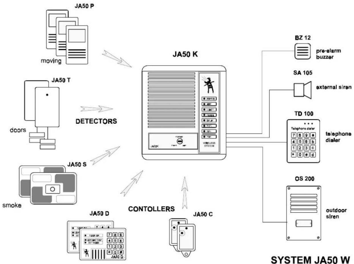
flowchart
graph TD
    A["JP50 P"] -->|DOORS| B["JP50 T"]
    B --> C["DOORS"]
    C --> D["JP50 S"]
    D --> E["JP50 K"]
    E --> F["JP50 K"]
    F --> G["JP50 K"]
    G --> H["BZ 12"]
    H --> I["pre-alarm buzzer"]
    G --> J["SA 105"]
    J --> K["external siren"]
    G --> L["TD 100"]
    L --> M["Telephone dialer"]
    M --> N["7 8 9 a"]
    M --> O["4 5 6 b"]
    M --> P["1 2 3 c"]
    M --> Q["* 0 # d"]
    L --> R["OS 200"]
    R --> S["outdoor siren"]
    E --> T["CONTOLLERS"]
    T --> U["JP50 D"]
    U --> V["JP50 C"]
    V --> W["JP50 D"]
8.1. More detectors
You can use as many JA-50 detectors as you need for your system. These detectors include the JA-50P (body movement detector), JA-50S (smoke detector) and JA-50T (Universal transmitter).
The universal transmitter can change any standard sensor into a wireless detector. For example you can combine it with the SA-200 magnetic switch to create a wireless door opening detector or with a GS-100 for a wireless gas leak detector.
Do not forget to set the HOUSE CODE when you install any new detector to your system.
8.2. More remote controls or digital keypads
The JA-50K control panel can learn up to ten controller codes. So, if you need to add a remote control, simply buy one and teach it to your system (see chapter 7.1. for more details).
The JA-50D keypad is especially suitable in the case that many users will operate the alarm system. You can add as many JA-50D keypads to your system as you need. This is possible because you are able to program all of them with the same communication code if necessary). Refer to the JA-50D manual for programming information.
8.3. Terminals of JA-50K control panel
There is an A.C power connector and 10 terminals on the PCB of the control panel. These are used for the A.C. power supply and to allow you to connect external devices.
Disconnect the A.C. adapter and the backup battery every time you work with any of these terminals.
Terminal description:
FIRE - output of fire alarm signal. This output is switched to the GND during the alarm period, if the alarm is triggered in the "FIRE" zone. Maximum load of this output is 0.2A/12V.
CHIME - output is switched to the GND during the entry delay. It can be used as an external pre-alarm buzzer. Maximum load of this output is 0.2A/12V.
GND - ground terminal (common negative pole)
+12 - back up voltage output for optional devices. Maximum current consumption is 500mA. This output is protected by a FU1(1.6A) fuse.
SIR, +SIR - external siren output, 12V/max.1A.
C,NC,NO - over switching dry contact of alarm output relay, max. load 1A/60V
B.S. - this terminal can be used for connection with an OS-200 outdoor back up siren. There is positive voltage provided by this terminal when there is no alarm condition.
AUX - these two terminals can be used as hard wire input for 24h zone (N.C. input)
9. Wiring of optional devices
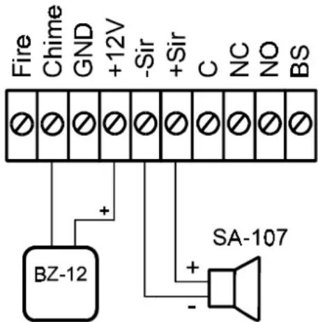
fig. 10
9.1. External pre-alarm buzzer
Use BZ-12 Jablotron buzzer for an external audible indication that entry delay timer has been triggered (see fig.10). This device warns you not to forget to disarm your alarm when you enter your home.
The buzzer should be installed close to the entrance, and away from the control panel.
You can switch off the internal buzzer if you install the external one.
9.2. External siren
Use SA-107 (piezo siren 123dB) or SA-114 (horn siren 115dB) as an external siren (see fig.10).
These sirens should be installed in a place that is not exposed to direct rain.

fig. 11
9.3. Outdoor siren OS-200
The OS-200 high powered electronic siren with rechargeable back-up battery is designed for outdoor installation. Solid double steel cover with an excellent anti corrosion protection provides resistance against physical tampering and atmospheric conditions.
Only two wires are necessary between the central unit and siren for both battery recharging and siren triggering (see fig.11).

9.4. Telephone dialer TD-100
This device can call for help automatically. When the alarm system activates the TD-100, it performs the following: the TD-100 automatically calls up to four programmed numbers. Each number can be up to 16 digits long. A prerecorded message is played for each telephone number dialed.
The auto dialer takes priority on your telephone line over incoming and outgoing phone calls (see fig. 12 for more information about connection with the JA-50K control panel).
We recommend professional installation of this device.
10. Important Warning
If there is any reason to switch your alarm system totally off, do not forget to disconnect the back up battery inside the control panel. If you leave it connected, it could be permanently damaged by becoming over discharged after a few months.
11. Specifications:
A.C. power 220V/50Hz (110V/60Hz), back-up battery 12V/1.2Ah, four zones (delay, instant, 24hr., fire), exit/entry delay programmable from 10 seconds to 5 minutes (20sec. factory default), alarm duration programmable from 10 seconds to 5 minutes (5 minutes factory default), built-in siren 120dB/1m, external siren output 12V/1A, dry contacts of alarm relay output max.1A/60V, back-up voltage output 12V/max.500mA, detectors powered by 9V batteries working distance detector - control panel 60m (open area), all the codes and settings are stored in non voltage EEPROM memory.
- WIRELESS ALARM SYSTEM
- JA-50
- installation manual
- BASIC INSTALLATION
- ADVANCED CUSTOMER MODIFICATION OF THE SYSTEM
- Before starting
- Required tools
- Installation of control panel
- Opening of control panel
- Fixing of control panel on the wall
- 3.3.Connection of A.C. adapter
- Back up battery installation
- Installation of detectors
- Preparation of detectors
- Location of motion detectors
- Motion detectors installation
- Determination of detectors to zones
- Walking test of JA-50P detector
- Testing
- Testing of complete system JA-50W
- This is the end of basic installation procedure.
- Detector setting
- Detector's HOUSE CODE
- Setting of a new HOUSE CODE in detectors
- The other DIP switches in detectors
- Control panel setting
- Control code setting (remote control or digital keypad)
- Setting procedure:
- Control panel HOUSE CODE setting
- Setting of EXIT/ENTRY delay
- Setting of alarm duration
- Loudness of arming confirmation, pre-alarm sound
- Switching off the built in siren
- System extension
- More detectors
- More remote controls or digital keypads
- Terminals of JA-50K control panel
- Terminal description:
- Wiring of optional devices
- External pre-alarm buzzer
- External siren
- Outdoor siren OS-200
- Telephone dialer TD-100
- Important Warning
- Specifications:
Marque : Jablotron
Modèle : JA50W
Catégorie : Caméra de surveillance