OS-365A - Caméra de surveillance Jablotron - Notice d'utilisation et mode d'emploi gratuit
Retrouvez gratuitement la notice de l'appareil OS-365A Jablotron au format PDF.


| Type de produit | Caméra de surveillance |
| Marque | Joblotron |
| Modèle | OS-365A |
| Dimensions | 12 x 8 x 6 cm |
| Poids | 250 g |
| Alimentation | 12V DC, 1A (adaptateur secteur inclus) |
| Résolution vidéo | 1080p Full HD (1920 x 1080 pixels) |
| Vision nocturne | Infrarouge jusqu'à 20 mètres |
| Angle de vue | 90 degrés |
| Connectivité | Wi-Fi 2.4 GHz, Ethernet RJ45 |
| Stockage | Carte microSD jusqu'à 128 Go, stockage cloud optionnel |
| Fonctions principales | Détection de mouvement, alertes push, audio bidirectionnel, enregistrement programmé |
| Audio | Microphone et haut-parleur intégrés |
| Installation | Montage mural ou sur support, application mobile gratuite |
| Entretien et nettoyage | Nettoyer la lentille avec un chiffon doux et sec ; ne pas utiliser de solvants |
| Sécurité | Cryptage AES, authentification à deux facteurs, accès protégé par mot de passe |
| Pièces détachées et réparabilité | Indice de réparabilité 7.5/10 ; pièces disponibles : adaptateur secteur, support, câble Ethernet |
| Garantie | 2 ans (hors pièces d'usure) |
| Température de fonctionnement | -10°C à 50°C |
| Humidité | Jusqu'à 90% sans condensation |
FOIRE AUX QUESTIONS - OS-365A Jablotron
Questions des utilisateurs sur OS-365A Jablotron
0 question sur cet appareil. Repondez a celles que vous connaissez ou posez la votre.
Poser une nouvelle question sur cet appareil
Téléchargez la notice de votre Caméra de surveillance au format PDF gratuitement ! Retrouvez votre notice OS-365A - Jablotron et reprennez votre appareil électronique en main. Sur cette page sont publiés tous les documents nécessaires à l'utilisation de votre appareil OS-365A de la marque Jablotron.
MODE D'EMPLOI OS-365A Jablotron
The OS-360A / OS-365A outdoor siren
The OS-360A / OS-365A is an outdoor siren with a rechargeable backup battery.
Model OS-360A is equipped with a piezo-electric siren mainly suitable for urban areas with a high building density. If necessary another piezo-electric siren (ACM-OS360) can be used.
Model OS-365A is equipped with a compressive magnetodynamic horn siren mainly suitable for family houses or for buildings with more space around them.
Two tamper sensors are built into the unit. They react to removing the cover from the unit or tearing the siren off its position. The siren's housing is made of mechanically, weather and UV-resistant plastic. The circuit board is protected against air humidity by a layer of special varnish.
The built-in flashing light can be operated separately.
Installation
The siren should be fixed to a place which is not easily accessible, but which allows for free sound transmission and, preferably, which is also protected against direct rain. It is recommended to position the siren in visible places to discourage criminals. It is also an advantage if the flashing light can be seen from a distance to help the police or security guards with locating the active siren.
Avoid installation near eaves where ice could form in winter.
- Remove the plastic cover by unscrewing the two screws under plastic caps (the cover remains hanging on a cord).
- Fix the siren's rear part onto the desired place.
- Route the cable into the siren through a suitable hole in the rear part and tighten the fixing screws.
- Connect the cable to the PCB terminals, first removing the PCBs protective plastic cover by unscrewing its fixing screw.
- Push the cable under the plastic tabs left of the PCB.
- Connect the back-up battery on the PCB, check that the sounder is connected too and replace the PCB cover.
- Put the siren unit's plastic cover back on and tighten the screws.
- Insert the plastic caps onto the screws
- Connect the power supply wires from the control panel to the siren and perform a function test.
Please keep in mind the high acoustic power of the siren and protect your hearing during testing.
Terminals
+12V - supply voltage (10 to 15 V DC)
GND – common ground
Power supply voltage drops cause the siren to sound (for 5 minutes maximum) and the flashing light to flash (for a period of 30 minutes).
SIR – siren activation (the flasher is not affected)
FLA – flashing light activation (the siren is not affected)
The SIR and FLA input terminals react to a connection/disconnection to/from GND according to the NO/NC setting of the jumper located on the siren circuit board (NO = react to a connection, NC = react to a disconnection).
ARM – a terminal for additional features
TMP, TMP – NC tamper switch output
Removing the siren cover or tearing the siren off its position causes the tamper switches to disconnect. The tamper sensors are connected in series with a 68R resistor which provides magnetic contact protection against faulty wiring.
There are also NiCd backup battery and siren connectors on the board. The NiCd backup battery comes from the factory disconnected. Only connect it during installation.
The ARM, FLA and SIR terminals can also be used for backup battery instantaneous voltage measurement. (e.g. during security system checking). You can perform the measurement remotely without any direct access to the siren. A voltage parameter is measured using a voltmeter on the corresponding wire (see Table 1) when the wire is disconnected from GND and the NC/NO jumper is set to ON.
| ARM disconnected | voltage during battery charging |
| FLA disconnected | voltage during flashing (battery load approx. 100mA) |
| SIR disconnected | voltage during siren sounding (battery load. approx. 1A) |
Table 1

Fig. 1 : Electronic circuit board front scheme
Setting jumpers
The three jumpers allow for the following settings:
| OK | ON | the siren flashes 1x in 45 sec (ready state indication) | |
| OFF | no ready state indication | ||
| NC/NO | ON | SIR and FLA inputs react to a disconnection from GND | |
| OFF | SIR and FLA inputs react to a connection to GND | ||
| FLASH | ON | flash for 30 minutes after a deactivation of the siren | |
| OFF | stop flashing immediately after a deactivation of the siren |
Table 2
You can take the circuit board out of the housing to get easier access to the jumpers.
Finishing installation, siren operation
Three seconds after being powered up (via the 12V terminal) the siren briefly flashes to indicate readiness for testing. Perform siren operation tests as described below to check if siren reactions correspond to the jumper setting.
Warning: If the SIR and FLA input terminals are in an activated state (according to the settings), then when the power is connected up the siren will start the sound / light after 3 sec.
Siren operation:
Power supply disconnection. A disconnection from the mains supply activates the siren – the siren starts to sound and flash. Restoring the power supply silences the siren with a 3 sec delay. If the power supply is permanently disconnected, then the siren sounding is stopped in 5 minutes. The flashing always continues for 30 minutes from the last power supply disconnection.
SIR activation. The siren starts to sound for 5 minutes without flash indication. A deactivation of the SIR input silences the siren immediately.
FLA activation. The flashing light starts to flash. Depending on the FLASH jumper setting, flash indication is terminated either immediately or 30 minutes after a deactivation of the siren.
ARM state change. Connecting ARM to GND causes the siren to indicate arming (setting): 1 flash plus 1 short beep. Disconnecting ARM from GND causes the siren to indicate disarming (unsetting): 1 flash plus 2 short beeps.
Ready state. Normal operation is indicated by the siren flashing once in every 45 seconds. This means that SIR and FLA are deactivated, there is a proper power supply and the backup battery is charged. This indication can be enabled/disabled by setting the OK jumper ON/OFF.
Control panel wiring examples
If wired according to figure 2, the siren sounds and flashes during the whole period of control panel alarms. The siren also provides an acoustic confirmation of system setting/unsetting. The flashing stops simultaneously with the sound.

Fig. 2 Connection to the JA-80K control panel
If wired according to figure 3, the siren sounds and flashes during the whole period of control panel alarms, with the light continuing to flash for 30 minutes after alarm deactivation. No confirmation of system setting/unsetting is provided, only a ready-state indication (1x flash in every 45 sec) which is independent of the system status.

Fig. 3 Connection to the JA-82K(R,C) control panel
If wired according to figure 4, the siren sounds and flashes during the whole period of control panel alarms, with the light continuing to flash for 30 minutes after alarm deactivation. Both acoustic confirmation of system setting/unsetting and ready-state indication are provided – 1x flash in every 45 sec, independently of the system status.
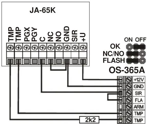
Fig. 4 Connection to the JA-65K control panel
If wired according to figure 5, the siren sounds and flashes during power supply faults, with the sound continuing for just 3 more seconds from the moment the power supply is restored. The flashing continues for 30 minutes. No confirmation of system setting/unsetting and no ready-state indication is provided.

Fig. 5 A simplified two-wired siren-connection
Maintenance
The siren does not need any special maintenance. The NiCd battery lifetime is about 3 years, depending on the working conditions. Specialized auto-recharge mode keeps the battery in optimum state. If the power supply (+12V and GND) is disconnected for a significantly long period of time, then also disconnect the battery. It is recommended to perform siren battery checking within general security system testing – you can check the battery remotely without any direct access to the siren.
Note: Whenever you handle any of the terminals (e.g. 12V disconnection) disconnect the battery to avoid siren activation.
Important: An activation of the siren with a disconnected sounder (see Fig. 1) does not cause any damage to the electronic circuits. Instead, a high voltage is produced on the sounder connector.
Specification
Power supply 10 to 15 V DC
Standby consumption < 50 mA / 12 V
Maximum load consumption < 800 mA /12 V
Backup battery NiCd pack 4.8 V / 1800 mAh
Lifetime approx. 3 years
Piezoelectric siren (OS-360) sound level 113 dB / 1 m
With second piezo-electric siren (ACM-OS360) 118 dB / 1 m
Electro-acoustic siren (OS-365) sound level 110 dB / 1 m
Siren timer max. 5 minutes
Flasher time alarm duration +15 minutes / 0
Resistance of the tamper loop < 70 Ω
Enclosure
IP
Security grade 2 EN 50131-1, CLC/TS 50131-4
Working environment class IV, outdoor general
Operational temperature -25 to +60°C
EMC EN 50130-4, EN 55022
Safety
EN 60950-1
Dimensions
230 × 158 × 75 mm

Jablotron Ltd. hereby declares that the OS-360A/365A is in compliance with the essential requirements and other relevant provisions of Directives 2004/108/EC and 2006/95/EC. The original of the conformity assessment can be found on the web site www.jablotron.com, Technical Support section.

Note: The NiCd backup battery contains cadmium (Cd). Dispose of batteries safely depending on battery type and local regulations. Although this product does not contain any harmful materials we suggest you return the product to the dealer or directly to the manufacturer after use.

Jablotron Ltd., Pod Skalkou 33
466 01 Jablonec nad Nisou
Czech Republic
Tel.: +420 483 559 911
fax: +420 483 559 993
Internet: www.jablotron.com
Marque : Jablotron
Modèle : OS-365A
Catégorie : Caméra de surveillance