
Beolab 5000 - Enceintes BANG & OLUFSEN - Notice d'utilisation et mode d'emploi gratuit
Retrouvez gratuitement la notice de l'appareil Beolab 5000 BANG & OLUFSEN au format PDF.

| Type de produit | Enceinte colonne amplifiée |
| Marque | Bang & Olufsen |
| Modèle | Beolab 5000 |
| Dimensions (L x H x P) | 45 x 101 x 8 cm |
| Poids | 15 kg |
| Alimentation | 220-240 V, 50/60 Hz, 130 W max, 2,6 W en veille |
| Puissance maximale (IEC long terme) | 120 W |
| Impédance | 8 ohms |
| Réponse en fréquence (+4/-8 dB) | 60 - 20 000 Hz |
| Haut-parleurs | 2 x 5" woofer, 1" tweeter |
| Fréquence de coupure | 3500 Hz |
| Principe de l'enceinte | Bass reflex |
| Amplificateur intégré | 65 W RMS DIN, <0,1% de distorsion |
| Fonctions audio | Dynamic Bass Equalizing, affichage du statut |
| Connectiques | POWER LINK (x2), SPEAKER LINK, LINE IN |
| Affichage | Volume, source, piste, balance, tonalité |
| Compatibilité | Récepteurs, téléviseurs et MCL B&O |
| Montage mural | Support fourni, fixation sur chevilles ou montants bois |
| Entretien | Polir avec chiffon doux sec, nettoyer avec détergent doux |
| Protection | Circuit anti-surchauffe, affichage ERROR/TURN OFF |
| Accessoires optionnels | Câbles Power Link, cache-câbles métal ou plastique |
| Garantie | Internationale, selon pays d'achat |
FOIRE AUX QUESTIONS - Beolab 5000 BANG & OLUFSEN
Questions des utilisateurs sur Beolab 5000 BANG & OLUFSEN
0 question sur cet appareil. Repondez a celles que vous connaissez ou posez la votre.
Poser une nouvelle question sur cet appareil
Téléchargez la notice de votre Enceintes au format PDF gratuitement ! Retrouvez votre notice Beolab 5000 - BANG & OLUFSEN et reprennez votre appareil électronique en main. Sur cette page sont publiés tous les documents nécessaires à l'utilisation de votre appareil Beolab 5000 de la marque BANG & OLUFSEN.
MODE D'EMPLOI Beolab 5000 BANG & OLUFSEN
Special note for the UK market:
IMPORTANT!
The wires in the mains lead supplied with this apparatus are coloured in accordance with the following code:
BLUE: NEUTRAL
BROWN: LIVE
As the colours of the wires in the mains lead of this apparatus may not correspond with the coloured markings identifying the terminals in your plug, proceed as follows:
- The wire which is coloured blue must be connected to the terminal which is marked with the letter N or coloured BLACK.
- The wire which is coloured brown must be connected to the terminal which is marked with the letter L or coloured RED.
Ensure that your equipment is connected correctly. If you are in any doubt, consult a qualified electrician.
Special note for the US market:
WARNING: To prevent fire or electric shock, do not expose this appliance to rain or moisture.

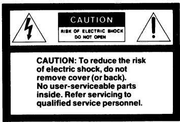
This symbol indicates that a dangerous voltage constituting a risk of electric shock is present within this unit.

This symbol indicates that there are important operating and maintenance instructions in the literature accompanying this unit.
This equipment generates and uses radio frequency energy and if not installed and used properly, that is, in strict accordance with the manufacturer's instructions, may cause interference to radio and television reception. It has been type tested and found to comply with the limits for a Class B computing device in accordance with the specifications in Subpart J of Part 15 of FCC Rules, which are designed to provide reasonable protection against such interference in a residential installation. However, there is no guarantee that interference will not occur in a particular installation. If this equipment does cause interference to radio or television reception, which can be determined by turning the equipment off and on, the user is encouraged to try to correct the interference by one or more of the following measures:
- Reorient the receiving antenna
- Relocate the computer with respect to the receiver
- Move the computer away from the receiver
- Plug the computer into a different outlet so that computer and receiver are on different branch circuits.
If necessary, the user should consult the dealer or an experienced radio/television technician for additional suggestions. The user may find the following booklet prepared by the Federal Communications Commission helpful:
"How to Identify and Resolve Radio-TV Interference Problems".
This booklet is available from the U.S. Government Printing Office, Washington, DC 20402, Stock No. 004-00345-4.
Beolab 3000
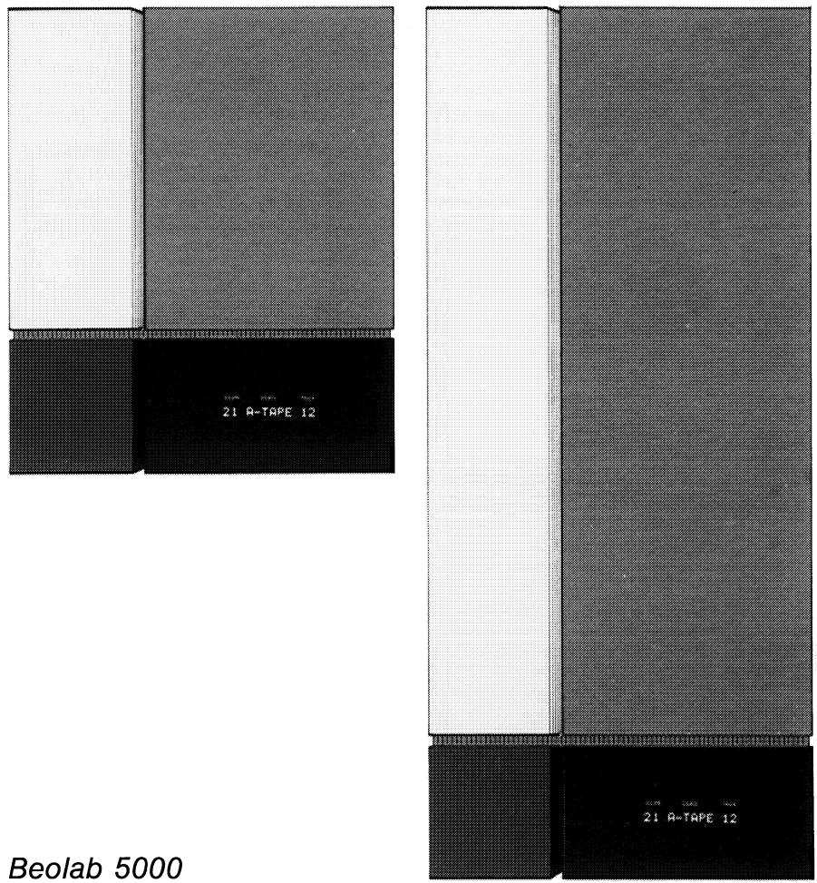
Beolab 5000
The Beolab 3000/5000 is a piece of functional art – a sophisticated combination of superb sound and unique design.
The loudspeaker unit is matched by a built-in amplifier which gives your music a tremendous boost, both in quantity and quality. And, to ensure the best sound possible, the speaker is equipped with the Dynamic Bass Equalizing system which extends the low-frequency performance.
If your Beolab 3000/5000 is connected to compatible Bang & Olufsen products, the display on the panel speaker will keep you informed about the current state of your audio or video system – accurately and yet discretely.
We are pleased that you have decided to bring the Bang & Olufsen panel loudspeaker into your family, and we feel confident that it will enhance the beauty of your home while giving you extraordinary musical experiences.
This manual describes how to mount the loudspeaker on your wall and how to connect and adjust it to your audio or video system.
Table of contents
4 Placement
4 Mounting your loudspeaker
6 Connections
9 Setting the switches on the rear side of the Beolab 3000/5000
11 VIDEO/AUDIO/OFF switch
12 Display
15 What's wrong?
16 Optional accessories
17 Maintenance
18 Developing a Bang & Olufsen loudspeaker
19 Technical specifications
20 International guarantee
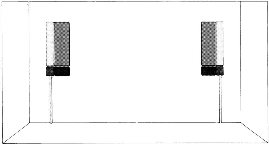
Placement
The Beolab 3000/5000 is designed to be hung on a wall. The wall is not used merely as a supporting structure – it is in fact essential to the sound of the speaker as it helps boost the bass response and ensures optimum speaker performance. Either speaker of the set supplied can be used as right or left speaker.
natural_image
Diagram of two identical rectangular electronic components mounted on a vertical rod, enclosed in a 3D cube frame (no text or symbols)Mounting your loudspeaker
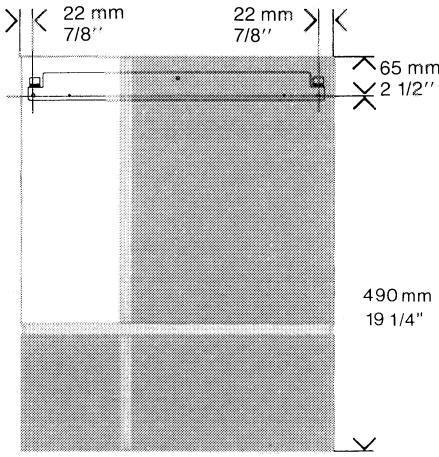
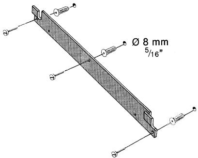
The panel speaker is supplied with a wall bracket on which to mount the speaker. When deciding where to drill the holes for the wall brackets, make sure that there is enough space for the speaker and for adjustment. Do not forget to allow for the Bang & Olufsen cable covers, if any (see page 17).
Beolab 3000:
Beolab 5000:

Using the screws and the wall anchors, fasten the bracket onto the wall.
Important installation note for the USA!
Interior walls are often constructed of gypsum panels – known as drywall or wallboard – secured to vertical wooden studs.
Wallboard is not satisfactory material to support the weight of the Beolab 3000/5000.
If you must mount the Beolab 3000/5000 on a wall of the previously mentioned nature, we recommend that at least one of the two mounting screws be a lag screw and that the lag screw be securely screwed into one of the wooden vertical wall studs.
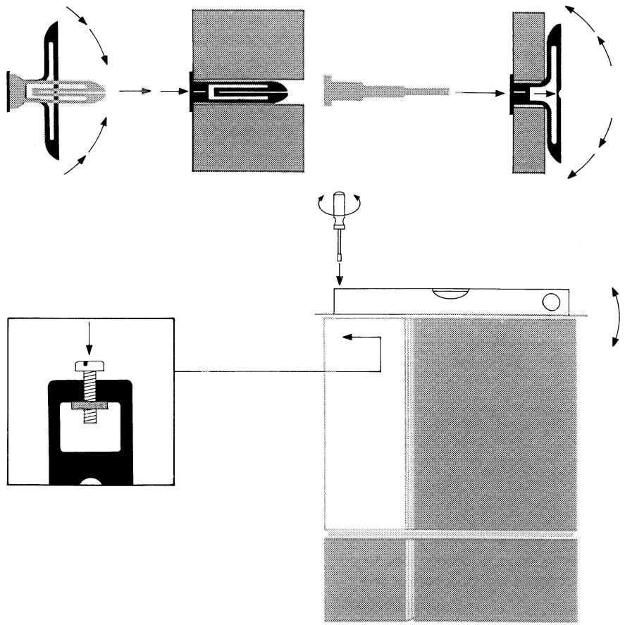
The wall anchors are of a special type. They can be used in both solid walls and light partition walls.
Squeeze the two flaps to insert the wall anchor into the hole.
If the wall anchor is used in a plaster board wall, the two flaps must be completely unfolded before the screw is inserted. Use the tool supplied to do so.
(We recommend that your carry out the connections described in the next section before mounting the Beolab 3000/5000 on the wall bracket).
When mounting the speaker on the wall bracket, make sure that it is seated securely on the hooks.
Adjust the adjustment screw up or down to ensure that the speaker is vertical and level.
flowchart
graph TD
    A["Initial Component"] --> B["Assembly Step 1"]
    B --> C["Assembly Step 2"]
    C --> D["Final Assembly Unit"]
    D --> E["Assembly Step 3"]
    E --> F["Final Assembly Unit"]
    style A fill:#f9f,stroke:#333
    style B fill:#ccf,stroke:#333
    style C fill:#cfc,stroke:#333
    style D fill:#fcc,stroke:#333
    style E fill:#cff,stroke:#333
    style F fill:#ffc,stroke:#333
Connections
The Beolab 3000/5000 can be connected to either a receiver, a TV set, a Master Control Link 2 A or a Master Control Link 2 AV (MCL 2 A/2 AV).
NOTE! Before connecting the Beolab 3000/5000 to the receiver, TV set or MCL 2 A/2 AV, make sure that the VIDEO/AUDIO/OFF switch on the side of the speaker is set to OFF. This precaution applies to both the initial set-up and to later rearrangements of connections.
Do not switch on your audio or video system until you have set the switches on the rear side of the speaker to their correct position (see pp 9-10).
To obtain a neat installation, you may run the cables in the grooves provided on the rear of the Beolab 3000/5000.
For lengths and part numbers of the cables which can be used, see the section "Optional accessories".
Connection to a Bang & Olufsen receiver or TV set or an MCL 2 A/2 AV
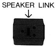
When connecting your Beolab 3000/5000, you may use either the POWER LINK socket or the SPEAKER LINK socket.
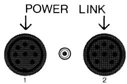
- POWER LINK 1 & POWER LINK 2 sockets (using an 8-pin DIN Power Link cable).
The sockets marked POWER LINK 1 & 2 are identical. This means that either socket can be used when you connect your Beolab 3000/5000 by means of a Power Link cable.
○ Plug one end of the cable into one of the POWER LINK sockets on the Beolab 3000/5000.
○ Plug the other end of the cable into one of the POWER LINK sockets on your receiver, TV set or MCL 2 AV.
○ Repeat the procedure for the other speaker.
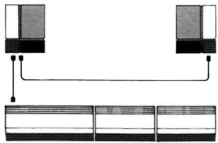
In order to avoid running cables from both speakers to your receiver, TV set or MCL 2 AV, you may loop the signal through:
○ Using one Power Link cable, connect one speaker to your receiver, TV set or MCL 2 AV.
○ Using the other Power Link cable, connect the speakers to one another.
natural_image
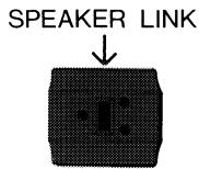
Pure diagram of two connected devices with a connecting line, no text or symbols present○ SPEAKER LINK socket (using a shielded cable with 2-pin, 3-pin or 4-pin DIN speaker plugs)
○ Plug one end of the cable into the SPEAKER LINK socket on the Beolab 3000/5000.
○ Plug the other end of the cable into the appropriate socket on your receiver, TV set or MCL 2 A/2 AV.
○ Repeat the procedure for the other speaker.
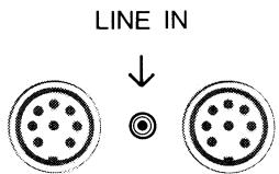
Connection to other receivers When connecting your Beolab 3000/5000, you may use either the SPEAKER LINK socket or the LINE IN socket.
○ SPEAKER LINK socket (using a shielded cable with 2-pin DIN speaker plugs)
○ Plug one end of the cable into the SPEAKER LINK socket on the Beolab 3000/5000.
○ Plug the other end of the cable into the appropriate loudspeaker socket on the receiver.
○ Repeat the procedure for the other speaker.
○ LINE IN socket (using a shielded cable with phono plugs)
○ Plug the appropriate cable end into the LINE IN socket on the Beolab 3000/5000.
○ Plug the other end of the cable into the appropriate phono socket (pre-amplifier output) on your receiver.
○ Repeat the procedure for the other speaker.
Setting the switches on the rear side of the Beolab 3000/5000
On the lower rear side of the speaker there are two switches:
○ The input level switch (the longer of the two - 4 settings)
○ The mode switch (the shorter of the two - 3 settings).
Input level switch
Set the input level switch to the position required to match the Beolab 3000/5000 to the output of your receiver or TV set. If in doubt about your receiver/TV output, consult your Bang & Olufsen dealer.
POWER LINK socket:
If you have connected your speaker via the POWER LINK socket, there are no requirements as to the setting of the input level switch, because the acoustic level is independent of the setting of the switch.
SPEAKER LINK socket:
| Switch position | Receiver/TV output* | |
| 4 ohm | 8 ohm | |
| — | - 40 W | - 20 W |
| ≡ | 40 - 80 W | 20 - 40 W |
| ≡ | 80 - W | 40 - W |
* 4 ohms and 8 ohms receiver/TV output specified for 4 and 8 ohms speaker impedance.
LINE IN socket:
Set the switch to N.


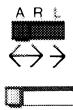
Mode switch
Once connected to the mains supply, the Beolab 3000/5000 is in the stand-by mode. The stand-by mode is indicated by a red light next to the display.
The speaker switches on automatically when it receives a signal, unless, of course, the VIDEO/AUDIO/OFF switch is set to OFF (see page 11).
Set the mode switch to either A, L (left) or R (right):
| Sockets | Mode switch |
| POWER LINK | |
| Left speaker | L |
| Right speaker | R |
| SPEAKER LINK | A |
| LINE IN | A |
When the TV set/receiver to which the Beolab 3000/5000 is connected goes into stand-by, the loud-speaker automatically switches itself off – i.e. reverts to the stand-by mode. This happens instantly if you have connected the speaker using a Power Link cable or a shielded 4-pin DIN speaker cable. In all other cases the Beolab 3000/5000 goes into stand-by after approx. 3 minutes.
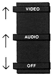
VIDEO/AUDIO/OFF switch
In order to obtain the right status reading from the display, the VIDEO/AUDIO/OFF switch must be set to the correct position:
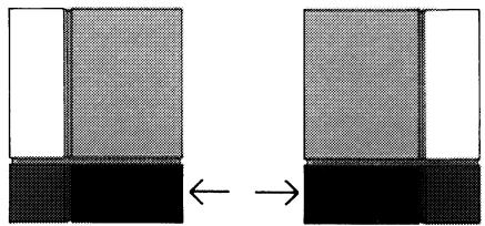
natural_image
Diagram showing two identical rectangular blocks with different fill patterns, connected by an arrow indicating transformation (no text or symbols present)VIDEO
if the Beolab 3000/5000 is connected to a Beovision.
AUDIO
if the Beolab 3000/5000 is connected to a Beomaster, Beocenter or MCL 2 A/2 AV.
For the use of the OFF position, see the sections "Connections" (page 6) and "What's wrong?" (page 15).
Display
If connected to a compatible Bang & Olufsen receiver, TV set or MCL 2 A/2 AV, your Beolab 3000/5000 displays information about the source of the sound reproduced by the speaker. However, in order to give full status reading in the display, the Beolab 3000/5000 must be connected to a Bang & Olufsen product with POWER LINK sockets. If you use a 4-pin DIN speaker cable to connect your Beolab 3000/5000
1
VOLUME
| 22 | Volume level |
| -- | Muted |
to the SPEAKER LINK socket on a Bang & Olufsen product equipped with POWER LINK sockets, you still get full reading in the display.
If the Beolab 3000/5000 is connected to a product without POWER LINK sockets, the status reading will be either slightly reduced or completely missing, depending on the product. If in doubt about which kind of status reading you can get, consult your Bang & Olufsen dealer.
2
SOURCE
| RADIO | Radio |
| CD | Compact disc player |
| PHONO | Record player |
| A-TAPE | Audio tape recorder |
| A-TP2 | Second audio tape recorder |
| A-AUX | Any source connected to the AUX/LINE socket on the receiver |
| TV | TV set |
| V-SAT | TV satellite program |
| V-TAPE | Video tape recorder |
| V-TP2 | Second video tape recorder |
| V-AUX | Any source connected to the AUX/LINE socket on the TV set |
| VOLUME | SOURCE | TRACK |
| 22 | A-TAPE | 11 |
| 1 | 2 | 3 |
The displayed cues and symbols are not all visible at the same time.
Recording:
| A-REC | Recording on audio tape recorder |
| V-REC | Recording on video tape recorder |
3
TRACK
| 12 | Track number on CD, audio tape or video tape; preset radio or TV station |
| > | Tuning up in frequency |
| < | Tuning down in frequency |
| >> | Fast forward (tape); search forward (CD) |
| << | Rewind (tape); search backward (CD) |
| < > | Stop; TV/radio frequency range |
| AM | AM radio station |
| FM | FM radio station |
2 + 3
Sound:
| VOLUME | 22 | Volume level |
| BAL | - - - | Neutral balance |
| 1 - - | Balance adjusted toward the left | |
| - - 1 | Balance adjusted toward the right | |
| TREBLE | - - | Neutral treble |
| + 1 | Increase in treble level | |
| - 1 | Decrease in treble level | |
| BASS | - - | Neutral bass |
| + 1 | Increase in bass level | |
| - 1 | Decrease in bass level | |
| LOUDN ON/OFF | Loudness on/off | |
Status reading on recording
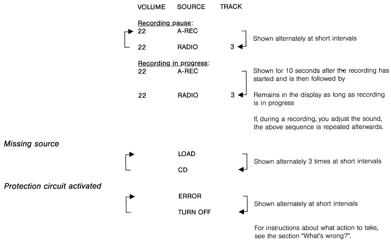
What's wrong?
Display shows ERROR/TURN OFF
The Beolab 3000/5000 features a protection circuit which is automatically activated if something is wrong, e.g.
- if the amplifier unit is overheated,
- if a fault occurs in the amplifier which could damage the loud-speaker units.
If the protection circuit is activated, the sound disappears and the display will alternately show ERROR and TURN OFF.
No display
Should this happen
○ set the VIDEO/AUDIO/OFF switch located on the side of the speaker to the OFF position,
○ allow the amplifier time to cool off,
○ set the VIDEO/AUDIO/OFF switch to the AUDIO or VIDEO position again.
If the sequence ERROR/TURN OFF is still shown in the display, contact your Bang & Olufsen dealer.
If there is no light in the display
○ disconnect the Beolab 3000/5000 from the mains supply,
○ reconnect the Beolab 3000/5000 to the mains supply.
If there is still no light in the display, contact your Bang & Olufsen dealer. Do not cut the power supply in and out several times in a row.
Optional accessories
The accessories listed below are all available as optional extras from your Bang & Olufsen dealer.
| Cables | Part No | |
| 4-pin DIN shielded speaker cables5 m (16') | 6270336 | |
| 10 m (33') | 6270352 | |
| 8-pin DIN Power Link cables2.5 m (8') | 6270417 | |
| 5 m (16') | 6270418 | |
| 10 m (33') | 6270419 | |
| 2-pin DIN shielded speaker cable5 m (16') | 6270350 | |
| Adaptor for Power Link | ||
| 8-pin DIN female/8-pinDIN female | 7229075 |
Cable covers
Metal finish:
| The Bang & Olufsen metal finish cable covers are designed to match and enhance the beauty of the Beolab 3000/5000 while concealing the speaker cables. They come in the following versions: | Cable Cover 5000, length 0.85 m ( 331/2 ") | 8960280 |
| Cable Cover 3000, length 1.30 m (51") | 8960290 |
Plastic:
| The Bang & Olufsen plastic cable covers are designed to help you conceal your cables in a neat way. They come in the following versions: | Length 2.50 m (98 12 ")Internal dimensions 10 x 20 mm ( 3/8 " x 3/4 ")Length 2.10 m (82")Internal dimensions 10 x 46 mm ( 3/8 " x 13/4 ") | 25602322560202 |
Maintenance
To make the stainless steel surfaces shiny, polish them thoroughly using a dry, soft cloth.
Remove fingerprints and grease stains using a mild detergent on a soft cloth.
Developing a Bang & Olufsen loudspeaker
For more than fifty years, we at Bang & Olufsen have been working at developing loudspeakers that combine a true-to-life sound reproduction and an innovative and unique design. In the process of research and development we draw on the skills of our in-house experts in acoustics, electronics and mechanical engineering. Their combined effort is aimed at developing prototypes which offer the best reproduction possible of tone balance and spatial impression.
Once produced, the prototype is subjected to a number of extensive tests. These tests enable us to see whether the loudspeaker's performance matches the conceptual idea, and if not, which modifications are required before the speaker is ready for production.
In pursuit of perfection, we use our highly sophisticated research facility: In a purpose-built cube-shaped test chamber (12 x 12 x 13 meter / 39' x 39' x 42') we analyze our speakers' performance under simulated free-field conditions. The test equipment and computers we use are capable of registering even the most microscopic deviations from the ideal we have chosen, and we can measure every detail of the large number of factors affecting the sound quality of the speaker.
The purpose of a loudspeaker cabinet is to isolate the rear side acoustical emission of the speaker units from the front side emission. A loudspeaker cabinet is also designed to act as a supporting structure for the speaker units without contributing any sound itself. As it is important to minimize mechanical vibrations in the cabinet, we use a highly sophisticated technique called laser holography: By studying the three-dimensional picture produced during the holographic test, we can actually see where in the cabinet undesirable vibrations are produced, and we can then take the steps needed to dampen them.
The above-mentioned testing techniques can all be classified as "objective tests", because the performance of the loudspeaker is evaluated on the basis of data provided by advanced technological equipment. However, as we develop loudspeakers for the pleasure of the human ear – and not merely for the impersonal acceptance of a machine – we also carry out a number of “subjective” listening tests: In our reference room for listening tests we gather an audience of people from our well-trained listening panel whose ears are tuned to the fine nuances and details of sound. Their expert opinion and highly personal comments are of the utmost value to us in our research and development work, and their acceptance is needed before the speaker can be given the final seal of approval.
Your new speaker is proof that Bang & Olufsen has come close to perfection in both sound reproduction and design.
Technical specifications
| Beolab 3000 | Beolab 5000 | |
| Speaker: | ||
| Long-term Maximum Power IEC | 90 watts | 120 watts |
| Maximum Noise Power | 45 watts | 60 watts |
| Impedance | 8 ohms | 8 ohms |
| Frequency range +4/-8 dB | 75-20,000 Hz | 60-20,000 Hz |
| Power at 94 dB SPL (1 m) | 5 watts | 3.2 watts |
| Sensitivity 1 W (1 m) | 87 dB | 89 dB |
| Distortion 0.250 - 1 kHz | <1% | <0.2% |
| 1 - 2 kHz | <0.7% | <0.2% |
| 2 - 6 kHz | <0.2% | <0.2% |
| Cabinet principle | Bass Reflex | Bass Reflex |
| Woofer | 5" | 2 x 5" |
| Tweeter | 1" | 1" |
| Crossover frequency | 3500 Hz | 3500 Hz |
| Net cabinet volume | 5.4 litres | 14 litres |
| Power amplifier: | ||
| Long-term Maximum Power IEC | 90 watts | 90 watts |
| RMS DIN | 65 watts | 65 watts |
| IHF | 55 watts | 55 watts |
| Total harmonic distortion IHF | <0.1% at 55 watts 20-20,000 Hz | <0.1% at 55 watts 20-20,000 Hz |
| Frequency range +0/-1 dB | 40-20,000 Hz | 40-20,000 Hz |
| Signal-to-noise ratio: | ||
| A-weighted 1 W | >80 dB | >80 dB |
| A-weighted max. power | >97 dB | >97 dB |
| Input sensitivity/impedance: | ||
| POWER LINK sockets | 1 V/100 kohms | 1 V/100 kohms |
| - channel separation | >66 dB | >66 dB |
| SPEAKER LINK socket | 11.3 - 16 - 22 V/>47 kohms | 11.3 - 16 - 22 V/>47 kohms |
| LINE IN socket | 1 V/33 kohms | 1 V/33 kohms |
| Dynamic bass equalizing | 6 - 0 dB | 4 - 0 dB |
| Power supply | Type 6711: 220 V | Type 6701: 220 V |
| Type 6712/15: 240 V | Type 6702/05: 240 V | |
| Type 6713: 120 V | Type 6703: 120 V | |
| Type 6714: 100 V | Type 6704: 100 V | |
| Power consumption | Max. 130 watts | Max. 130 watts |
| Stand-by | 2.6 watts | 2.6 watts |
| Dimensions W x H x D | 45 x 54 x 8 cm (17 3/4 " x 21 1/4 " x 3 1/8 ") | 45 x 101 x 8 cm (17 3/4 " x 39 3/4 " x 3 1/8 ") |
| Weight | 9 kg (19.8 lbs) | 15 kg (33 lbs) |
Subject to change without notice
International guarantee
This Bang & Olufsen product carries a guarantee against defects in workmanship and materials. It is a national guarantee, extended by Bang & Olufsen to the country in which the product was bought. The terms of the guarantee apply principally to the country of purchase but will be met by authorized Bang & Olufsen dealers in other countries. The guarantee period applying to the country of purchase takes priority over guarantee periods applying in other countries, even where differences exist.
In order to obtain service under this guarantee, a certificate stating the following information is required:
– Name of product and type number
- Serial number
- Date of purchase
- Guarantee period
– Dealer's or supplier's signature
Bang & Olufsen DK-7600 Struer DENMARK


- Special note for the UK market:
- IMPORTANT!
- Special note for the US market:
- Table of contents
- Placement
- Mounting your loudspeaker
- Important installation note for the USA!
- Connections
- Setting the switches on the rear side of the Beolab 3000/5000
- Input level switch
- POWER LINK socket:
- LINE IN socket:
- Mode switch
- VIDEO/AUDIO/OFF switch
- VIDEO
- AUDIO
- Display
- Status reading on recording
- What's wrong?
- Display shows ERROR/TURN OFF
- Should this happen
- Optional accessories
- Cable covers
- Maintenance
- Developing a Bang & Olufsen loudspeaker
- International guarantee
Marque : BANG & OLUFSEN
Modèle : Beolab 5000
Catégorie : Enceintes