
DSL-2730U - Routeur ADSL D-LINK - Notice d'utilisation et mode d'emploi gratuit
Retrouvez gratuitement la notice de l'appareil DSL-2730U D-LINK au format PDF.

| Type de produit | Routeur ADSL sans fil |
| Marque | D-LINK |
| Modèle | DSL-2730U |
| Interfaces | 1 port RJ-11 ADSL, 4 ports RJ-45 10/100 Ethernet, Wi-Fi 802.11b/g/n |
| Normes ADSL | ANSI T1.413, ITU G.992.1 (G.dmt), G.992.2 (G.lite), G.992.3 (ADSL2), G.992.5 (ADSL2+) |
| Débit ADSL max | Jusqu'à 24 Mb/s descendant / 1 Mb/s montant (ADSL2+) |
| Débit Wi-Fi max | Jusqu'à 130 Mb/s (802.11n) |
| Alimentation | Adaptateur secteur 12 V CC, 1 A (estimation) |
| Dimensions (approx.) | 180 x 120 x 35 mm |
| Poids (approx.) | 300 g |
| Fonctions principales | NAT, serveur DHCP, pare-feu, filtrage IP, contrôle parental, QoS, VPN IPSec, DMZ, serveurs virtuels |
| Sécurité Wi-Fi | WEP, WPA, WPA2 |
| Gestion | Interface web (HTTP), SNMP, Telnet, TR-069 |
| Contenu du carton | Routeur, adaptateur secteur, câble RJ-11, câble RJ-45, CD-ROM, guide d'installation rapide |
| Entretien | Maintenir à l'abri de l'humidité et de la chaleur excessive ; nettoyer avec un chiffon sec |
| Sécurité | Utiliser uniquement l'adaptateur fourni ; ne pas exposer à l'eau ; débrancher avant nettoyage |
| Pièces détachées / Réparabilité | Adaptateur secteur et câbles disponibles auprès du service après-vente |
FOIRE AUX QUESTIONS - DSL-2730U D-LINK
Questions des utilisateurs sur DSL-2730U D-LINK
0 question sur cet appareil. Repondez a celles que vous connaissez ou posez la votre.
Poser une nouvelle question sur cet appareil
Téléchargez la notice de votre Routeur ADSL au format PDF gratuitement ! Retrouvez votre notice DSL-2730U - D-LINK et reprennez votre appareil électronique en main. Sur cette page sont publiés tous les documents nécessaires à l'utilisation de votre appareil DSL-2730U de la marque D-LINK.
MODE D'EMPLOI DSL-2730U D-LINK
USER MANUAL
DSL-2730U
VERSION 1.00
Table of Contents
PACKAGE CONTENTS 4
SYSTEM REQUIREMENTS 4
FEATURES 5
HARDWARE OVERVIEW 7
Connections 7
LEDs 8
INSTALLATION 9
BEFORE YOU BEGIN 9
INSTALLATION NOTES 10
INFORMATION YOU WILL NEED FROM YOUR ADSL SERVICE PROVIDER 12
INFORMATION YOU WILL NEED ABOUT DSL-2730U 14
DEVICE INSTALLATION 16
Power on Router 16
Factory Reset Button 17
Network Connections 17
CONFIGURATION 18
WEB-BASED CONFIGURATION UTILITY 18
DEVICE INFO 19
SUMMARY 20
WAN 21
STATISTICS 22
ROUTE 25
ARP 25
DHCP 25
ADVANCED SETUP 26
LAYER2 INTERFACE 26
ATM Interface 27
WAN SERVICE 28
LAN 46
NAT 48
Virtual Servers 48
Port Triggering 49
DMZ Host 50
SECURITY 51
IP Filtering 51
PARENTAL CONTROL 55
URL Filter 56
QUALITY OF SERVICE 57
Queue Config. 58
QoS Classification 59
ROUTING 60
Default Gateway 60
Static Route 60
Policy Routing 61
RIP 62
DNS 63
DNS Server 63
Dynamic DNS 63
DSL 65
UPNP 68
DNS PROXY 68
INTERFACE GROUP 69
IPSEC 70
MULTICAST 72
WIRELESS 73
BASIC 73
SECURITY 74
MAC FILTER 75
WIRELESSBRIDGE 76
ADVANCED 77
STATION INFO 78
DIAGNOSTICS 79
MANAGEMENT 79
SETTING 80
SYSTEMLOG 80
SNMP AGENT 82
TR-069CLIENT 83
INTERNET TIME 84
ACCESS CONTROL 85
Passwords 85
UPDATE SOFTWARE 86
REBOOT 86
Table of Contents
TROUBLESHOOTING 87
NETWORKING BASICS 89
CHECK YOUR IP ADDRESS 89
STATICALLY ASSIGN AN IP ADDRESS 90
TECHNICAL SPECIFICATIONS 91
Package Contents
- DSL-2730U Wireless ADSL Router
Power Adapter - CD-ROM with User Manual
One Micro Splitter
One twisted-pair telephone cable used for ADSL connection
One straight-through Ethernet cable
One Quick Installation Guide
Note: Using a power supply with a different voltage rating than the one included with the DSL-2730U will cause damage and void the warranty for this product.
System Requirements
- ADSL Internet service
Computer with:
200MHz Processor
64MB Memory
- CD-ROM Drive
- Ethernet Adapter with TCP/IP Protocol Installed
- Internet Explorer v6 or later, Firefox v1.5
- Computer with Windows 2000, Windows XP, or Windows Vista
Features
- PPP (Point-to-Point Protocol) Security - The DSL-2730U ADSL Router supports PAP (Password Authentication Protocol) and CHAP (Challenge Handshake Authentication Protocol) for PPP connections. The Router also supports MSCHAP.
- DHCP Support - Dynamic Host Configuration Protocol automatically and dynamically assigns all LAN IP settings to each host on your network. This eliminates the need to reconfigure every host whenever changes in network topology occur.
- Network Address Translation (NAT) - For small office environments, the DSL-2730U allows multiple users on the LAN to access the Internet concurrently through a single Internet account. This provides Internet access to everyone in the office for the price of a single user. NAT improves network security in effect by hiding the private network behind one global and visible IP address. NAT address mapping can also be used to link two IP domains via a LAN-to-LAN connection.
- TCP/IP (Transfer Control Protocol/Internet Protocol) - The DSL-2730U supports TCP/IP protocol, the language used for the Internet. It is compatible with access servers manufactured by major vendors.
- RIP-1/RIP-2 - The DSL-2730U supports both RIP-1 and RIP-2 exchanges with other routers. Using both versions lets the Router to communicate with all RIP enabled devices.
Static Routing – This allows you to select a data path to a particular network destination that will remain in the routing table and never “age out”. If you wish to define a specific route that will always be used for data traffic from your LAN to a specific destination within your LAN (for example to another router or a server) or outside your network (to an ISP defined default gateway for instance). - Default Routing – This allows you to choose a default path for incoming data packets for which the destination address is unknown. This is particularly useful when/if the Router functions as the sole connection to the Internet.
- ATM (Asynchronous Transfer Mode) - The DSL-2730U supports Bridged Ethernet over ATM (RFC1483), IP over ATM (RFC1577), and PPP over ATM (RFC 2364).
- Precise ATM Traffic Shaping - Traffic shaping is a method of controlling the flow rate of ATM data cells. This function helps to establish the Quality of Service for ATM data transfer.
G.hs (Auto-handshake) - This allows the Router to automatically choose either the G.lite or G.dmt ADSL connection standards.
- High Performance - Very high rates of data transfer are possible with the Router. Up to 8 Mbps downstream bit rate using the G.dmt standard.
Full Network Management - The DSL-2730U incorporates SNMP (Simple Network Management Protocol) support for web-based management and text-based network management via an RS-232 or Telnet connection.
- Telnet Connection - The Telnet enables a network manager to access the Router's management software remotely.
- Easy Installation - The DSL-2730U uses a web-based graphical user interface program for convenient management access and easy set up. Any common web browser software can be used to manage the Router.
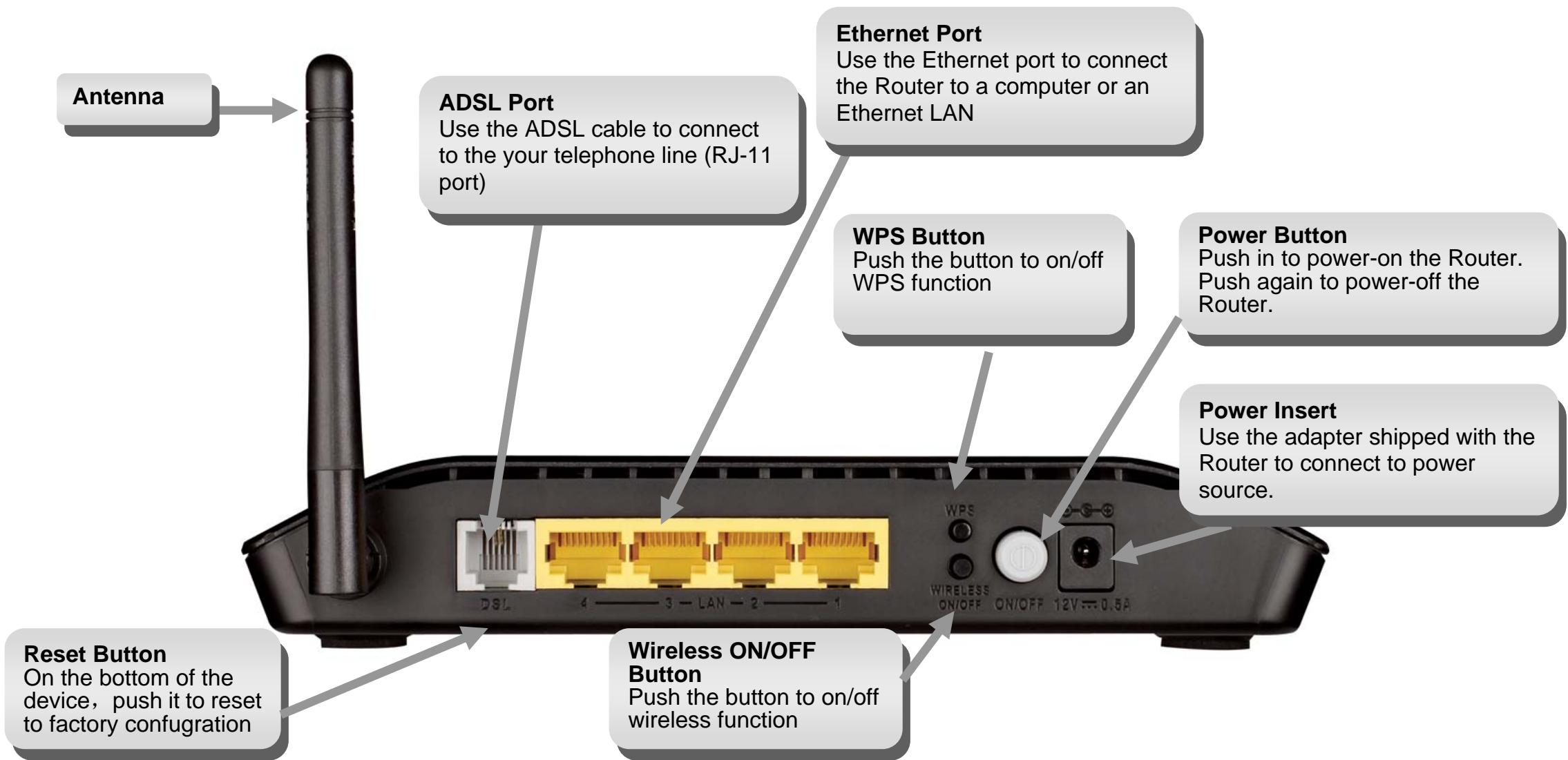
Hardware Overview
Connections
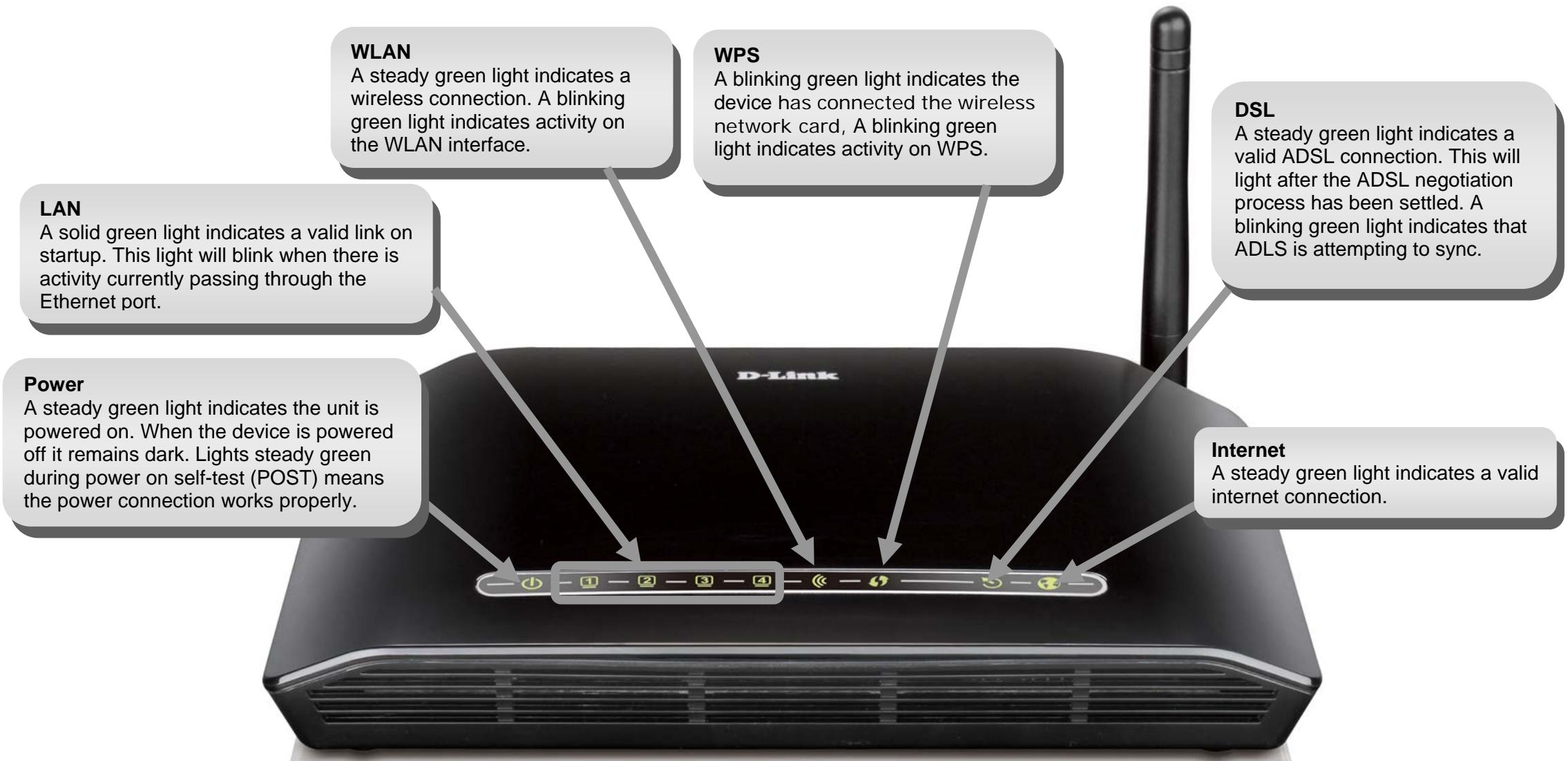
Hardware Overview LEDs
Installation
This section will walk you through the installation process. Placement of the Router is very important. Do not place the Router in an enclosed area such as a closet, cabinet, or in the attic or garage.
Before You Begin
Please read and make sure you understand all the prerequisites for proper installation of your new Router. Have all the necessary information and equipment on hand before beginning the installation.
Installation Notes
In order to establish a connection to the Internet it will be necessary to provide information to the Router that will be stored in its memory. For some users, only their account information (Username and Password) is required. For others, various parameters that control and define the Internet connection will be required. You can print out the two pages below and use the tables to list this information. This way you have a hard copy of all the information needed to setup the Router. If it is necessary to reconfigure the device, all the necessary information can be easily accessed. Be sure to keep this information safe and private.
Low Pass Filters
Since ADSL and telephone services share the same copper wiring to carry their respective signals, a filtering mechanism may be necessary to avoid mutual interference. A low pass filter device can be installed for each telephone that shares the line with the ADSL line. These filters are easy to install passive devices that connect to the ADSL device and/or telephone using standard telephone cable. Ask your service provider for more information about the use of low pass filters with your installation.
Operating Systems
The DSL-2730U uses an HTML-based web interface for setup and management. The web configuration manager may be accessed using any operating system capable of running web browser software, including Windows 98 SE, Windows ME, Windows 2000, Windows XP, and Windows Vista.
Web Browser
Any common web browser can be used to configure the Router using the web configuration management software. The program is designed to work best with more recently released browsers such as Opera, Microsoft Internet Explorer® version 6.0, Netscape Navigator® version 6.2.3, or later versions. The web browser must have JavaScript enabled. JavaScript is enabled by default on many browsers. Make sure JavaScript has not been disabled by other software (such as virus protection or web user security packages) that may be running on your computer.
Ethernet Port (NIC Adapter)
Any computer that uses the Router must be able to connect to it through the Ethernet port on the Router. This connection is an Ethernet connection and therefore requires that your computer be equipped with an Ethernet port as well. Most notebook computers are now sold with an Ethernet port already installed. Likewise, most fully assembled desktop computers come with an Ethernet NIC adapter as standard equipment. If your computer does not have an Ethernet port, you must install an Ethernet NIC adapter before you can use the Router. If you must install an adapter, follow the installation instructions that come with the Ethernet NIC adapter.
Additional Software
It may be necessary to install software on your computer that enables the computer to access the Internet. Additional software must be installed if you are using the device a simple bridge. For a bridged connection, the information needed to make and maintain the Internet connection is stored on another computer or gateway device, not in the Router itself.
If your ADSL service is delivered through a PPPoE or PPPoA connection, the information needed to establish and maintain the Internet connection can be stored in the Router. In this case, it is not necessary to install software on your computer. It may however be necessary to change some settings in the device, including account information used to identify and verify the connection.
All connections to the Internet require a unique global IP address. For bridged connections, the global IP settings must reside in a TCP/IP enabled device on the LAN side of the bridge, such as a PC, a server, a gateway device such as a router or similar firewall hardware. The IP address can be assigned in a number of ways. Your network service provider will give you instructions about any additional connection software or NIC configuration that may be required.
Information you will need from your ADSL service provider
Username
This is the username used to log on to your ADSL service provider's network. Your ADSL service provider uses this to identify your account.
Password
This is the Password used, in conjunction with theUsername above, to log on to your ADSL service provider's network. This is used to verify the identity of your account.
WAN Setting / Connection Type
These settings describe the method your ADSL service provider uses to transport data between the Internet and your computer. Most users will use the default settings. You may need to specify one of the following WAN Setting and Connection Type configurations (Connection Type settings listed in parenthesis):
- PPPoE/PPoA (PPPoE LLC, PPPoA LLC or PPPoA VC-Mux)
- Bridge Mode (1483 Bridged IP LLC or 1483 Bridged IP VC Mux)
- IPOA/MER (Static IP Address) (Bridged IP LLC, 1483 Bridged IP VC Mux, 1483 Routed IP LLC, 1483 Routed IP VC-Mux or IPOA)
- MER (Dynamic IP Address) (1483 Bridged IP LLC or 1483 Bridged IP VC-Mux)
Modulation Type
ADSL uses various standardized modulation techniques to transmit data over the allotted signal frequencies. Some users may need to change the type of modulation used for their service. The default DSL modulation (ADSL2+ Multi-Mode) used for the Router automatically detects all types of ADSL, ADSL2, and ADSL2+ modulation.
Security Protocol
This is the method your ADSL service provider will use to verify yourUsername and Password when you log on to their network. Your Router supports the PAP and CHAP protocols.
VPI
Most users will not be required to change this setting. The Virtual Path Identifier (VPI) is used in conjunction with the Virtual Channel Identifier (VCI) to identify the data path between your ADSL service provider's network and your computer. If you are setting up the Router for multiple virtual connections, you will need to configure the VPI and VCI as instructed by your ADSL service provider for the additional connections. This setting can be changed in the WAN Settings window of the web management interface.
VCI
Most users will not be required to change this setting. The Virtual Channel Identifier (VCI) used in conjunction with the VPI to identify the data path between your ADSL service provider's network and your computer. If you are setting up the Router for multiple virtual connections, you will need to configure the VPI and VCI as instructed by your ADSL service provider for the additional connections. This setting can be changed in the WAN Settings window of the web management interface.
Information you will need about DSL- 2730U
Username
This is theUsername needed to access the Router's management interface. When you attempt to connect to the device through a web browser you will be prompted to enter thisUsername. The defaultUsername for the Router is "admin." The user cannot change this.
Password
This is the Password you will be prompted to enter when you access the Router's management interface. The default Password is "admin." The user may change this.
LAN IP addresses for the DSL-2730U
This is the IP address you will enter into the Address field of your web browser to access the Router's configuration graphical user interface (GUI) using a web browser. The default IP address is 192.168.1.1. This may be changed to suit any IP address scheme the user desires. This address will be the base IP address used for DHCP service on the LAN when DHCP is enabled.
LAN Subnet Mask for the DSL-2730U
This is the subnet mask used by the DSL-2730U, and will be used throughout your LAN. The default subnet mask is 255.255.255.0. This can be changed later.
Information you will need about your LAN or computer:
Ethernet NIC
If your computer has an Ethernet NIC, you can connect the DSL-2730U to this Ethernet port using an Ethernet cable. You can also use the Ethernet ports on the DSL-2730U to connect to other computer or Ethernet devices.
DHCP Client status
Your DSL-2730U ADSL Router is configured, by default, to be a DHCP server. This means that it can assign an IP address, subnet mask, and a default gateway address to computers on your LAN. The default range of IP addresses the DSL-2730U will assign are from 192.168.1.2 to 192.168.1.254. Your computer (or computers) needs to be configured to obtain an IP address automatically (that is, they need to be configured as DHCP clients.)
It is recommended that your collect and record this information here, or in some other secure place, in case you have to re-configure your ADSL connection in the future.
Once you have the above information, you are ready to setup and configure your DSL-2730U ADSL Router.
Device Installation
The DSL-2730U connects two separate physical interfaces, an ADSL (WAN) and an Ethernet (LAN) interface. Place the Router in a location where it can be connected to the various devices as well as to a power source. The Router should not be located where it will be exposed to moisture or excessive heat. Make sure the cables and power cord are placed safely out of the way so they do not create a tripping hazard. As with any electrical appliance, observe common sense safety procedures.
The Router can be placed on a shelf or desktop, ideally you should be able to see the LED indicators on the front if you need to view them for troubleshooting.
Power on Router
The Router must be used with the power adapter included with the device.
- Insert the DC Power Adapter cord into the power receptacle located on the rear panel of the Router and plug the adapter into a suitable nearby power source.
- Depress the Power button into the on position. You should see the Power LED indicator light up and remain lit. The Status LED should light solid green and begin to blink after a few seconds.
- If the Ethernet port is connected to a working device, check the LAN LED indicators to make sure the connection is valid. The Router will attempt to establish the ADSL connection, if the ADSL line is connected and the Router is properly configured this should light up after several seconds. If this is the first time installing the device, some settings may need to be changed before the Router can establish a connection.
Factory Reset Button
The Router may be reset to the original factory default settings by using a ballpoint or paperclip to gently push down the reset button in the following sequence:
- Press and hold the reset button while the device is powered off.
- Turn on the power.
- Wait for 10 seconds and then release the reset button.
Remember that this will wipe out any settings stored in flash memory including user account information and LAN IP settings. The device settings will be restored to the factory default IP address 192.168.1.1 and the subnet mask is 255.255.255.0, the default management username is "admin" and the default Password is "admin."
Network Connections
Connect ADSL Line
Use the ADSL cable included with the Router to connect it to a telephone wall socket or receptacle. Plug one end of the cable into the ADSL port (RJ-11 receptacle) on the rear panel of the Router and insert the other end into the RJ-11 wall socket. If you are using a low pass filter device, follow the instructions included with the device or given to you by your service provider. The ADSL connection represents the WAN interface, the connection to the Internet. It is the physical link to the service provider's network backbone and ultimately to the Internet.
Connect RoutertoEthernet
The Router may be connected to a single computer or Ethernet device through the 10BASE-TX Ethernet port on the rear panel. Any connection to an Ethernet concentrating device such as a switch or hub must operate at a speed of 10/100 Mbps only. When connecting the Router to any Ethernet device that is capable of operating at speeds higher than 10Mbps, be sure that the device has auto-negotiation (NWay) enabled for the connecting port. Use standard twisted-pair cable with RJ-45 connectors. The RJ-45 port on the Router is a crossed port (MDI-X). Follow standard Ethernet guidelines when deciding what type of cable to use to make this connection. When connecting the Router directly to a PC or server use a normal straight-through cable. You should use a crossed cable when connecting the Router to a normal (MDI-X) port on a switch or hub. Use a normal straight-through cable when connecting it to an uplink (MDI-II) port on a hub or switch. The rules governing Ethernet cable lengths apply to the LAN to Router connection. Be sure that the cable connecting the LAN to the Router does not exceed 100 meters.
Hub or Switch to Router Connection
Connect the Router to an uplink port (MDI-II) on an Ethernet hub or switch with a straight-through cable. If you wish to reserve the uplink port on the switch or hub for another device, connect to any on the other MDI-X ports (1x, 2x, etc.) with a crossed cable.
Computer to Router Connection
You can connect the Router directly to a 10/100BASE-TX Ethernet adapter card (NIC) installed on a PC using the Ethernet cable provided.
D-Link DSL-2730U User Manual
Configuration
This section will show you how to configure your new D-Link Router using the web-based configuration utility.
Web-based Configuration Utility
Connect to the Router
The default IP address for ADSL MODEM is: 192.168.1.1; The Subnet Mask is : 255.255.255.0. Users can configure ADSL MODEM through an Internet browser. ADSL MODEM can be used as gateway and DNS server; users need to set the computer's TCP/IP protocol as follow:
- Set the computer IP address at same segment of ADSL MODEM, such as set the IP address of the network card to one of the "192.168.1.2" "192.168.1.254".
- Set the computer's gateway the same IP address as the ADSL Modem's.
- Set computer's DNS server the same as ADSL Modem's IP address or that of an effective DNS server.
To access the configuration utility, open a web-browser such as Internet Explorer and enter the IP address of the router (192.168.1.1).
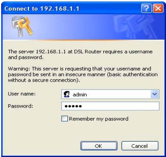
Type "admin" for the User Name and "admin" in the Password field. If you get a Page Cannot be Displayed error, please refer to the Troubleshooting section for assistance.
Device Info
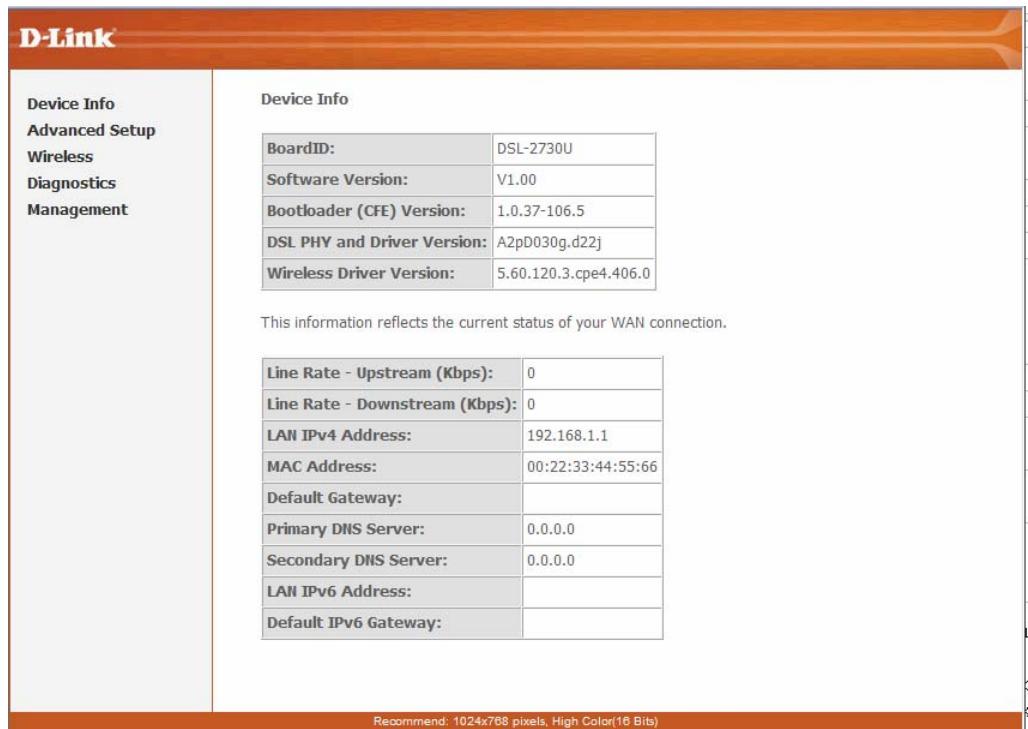
To access the Device Info window, click either the Device Info or Summary button in the Device Info directory. The following page opens:
Summary
To access the Router's first Summary window, click the Summary button in the Device Info directory.
This window displays the current status of your DSL connection, including the software version, LAN IP address, and DNS server address.
Device Info
| BoardID: | DSL-2730U |
| Software Version: | V1.00 |
| Bootloader (CFE) Version: | 1.0.37-106.5 |
| DSL PHY and Driver Version: | A2pD030g.d22j |
| Wireless Driver Version: | 5.60.120.3.cpe4.406.0 |
This information reflects the current status of your WAN connection.
| Line Rate - Upstream (Kbps): | 0 |
| Line Rate - Downstream (Kbps): | 0 |
| LAN IPv4 Address: | 192.168.1.1 |
| MAC Address: | 00:22:33:44:55:66 |
| Default Gateway: | |
| Primary DNS Server: | 0.0.0.0 |
| Secondary DNS Server: | 0.0.0.0 |
| LAN IPv6 Address: | |
| Default IPv6 Gateway: |
WAN
To access the WAN Info window, click the WAN button in the Device Info directory.
This window displays the current status of your WAN connection.
WAN Info
| Interface | Description | Type | VlanMuxId | IPv6 | Igmp | MLD | NAT | Firewall | Status | IPv4 Address |
Statistics
To access the Router's first Statistics window, click the Statistics button in the Device Info directory.
This window displays the Router's LAN statistics. Click the Reset Statistics button to refresh these statistics.
Statistics--LAN
| Interface | Received | Transmitted | ||||||
| Bytes | Pkts | Errs | Drops | Bytes | Pkts | Errs | Drops | |
| eth3 | 0 | 0 | 0 | 0 | 0 | 0 | 0 | 0 |
| eth2 | 65809 | 532 | 0 | 0 | 263904 | 437 | 0 | 0 |
| eth1 | 0 | 0 | 0 | 0 | 0 | 0 | 0 | 0 |
| eth0 | 0 | 0 | 0 | 0 | 0 | 0 | 0 | 0 |
| wlo | 90 | 1 | 0 | 0 | 2781 | 29 | 162 | 0 |
Reset Statistics
This window displays the Router's WAN statistics. Click the Reset Statistics button to refresh these statistics.
Statistics--WAN
| Interface | Description | Received | Transmitted | ||||||
| Bytes | Pkts | Errs | drops | Bytes | Pkts | Errs | drops | ||
Reset Statistics
This window displays the Router's XTM statistics. Click the Reset button to refresh these statistics.
Interface Statistics
| Port Number | In Octets | Out Octets | In Packets | Out Packets | In OAM Cells | Out OAM Cells | In ASM Cells | Out ASM Cells | In Packet Errors | In Cell Errors |
Reset
This window displays the Router's xDSL statistics. Click the Reset Statistics button to refresh these statistics.
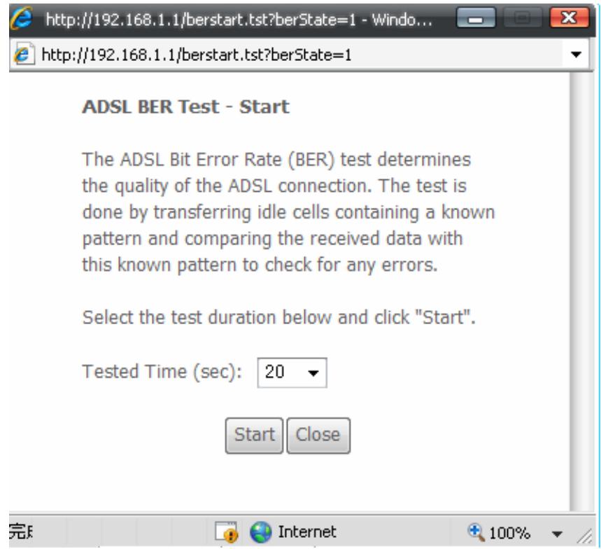
Click the xDSL BER Test button to access the ADSL Bit Error Rate Test window displayed below:
Statistics--xDSL
| Mode: | ||
| Traffic Type: | ||
| Status: | Disabled | |
| Link Power State: | L3 | |
| Downstream | Upstream | |
| Line Coding(Trellis): | ||
| SNR Margin (0.1 dB): | ||
| Attenuation (0.1 dB): | ||
| Output Power (0.1 dBm): | ||
| Attainable Rate (Kbps): | ||
| Rate (Kbps): | ||
| Super Frames: | ||
| Super Frame Errors: | ||
| RS Words: | ||
| RS Correctable Errors: | ||
| RS Uncorrectable Errors: | ||
| HEC Errors: | ||
| OCD Errors: | ||
| LCD Errors: | ||
| Total Cells: | ||
| Data Cells: | ||
| Bit Errors: | ||
| Total ES: | ||
| Total SES: | ||
| Total UAS: | ||
Route
To access the Device Info - Route window, click the Route button in the Device Info directory.
This read-only window displays routing info.
Device Info -- Route
Flags: U - up, ! - reject, G - gateway, H - host, R - reinstall D - dynamic (redirect), M - modified (redirect).
| Destination | Gateway | Subnet Mask | Flag | Metric | Service | Interface |
| 192.168.1.0 | 0.0.0.0 | 255.255.255.0 | U | 0 | br0 |
ARP
To access the Device Info - ARP window, click the ARP button in the Device Info directory.
This read-only window displays Address Resolution Protocol info.
Device Info - ARP
| IP address | Flags | HW Address | Device |
| 192.168.1.17 | Complete | 00:1A:A0:22:30:10 | br0 |
DHCP
To access the Device Info - DHCP Leases window, click the DHCP button in the Device Info directory.
This read-only window displays DHCP lease info.
Device Info - DHCP Leases
| Hostname | MAC Address | IP Address | Expires In |
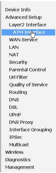
Advanced Setup
This chapter includes the more advanced features used for network management and security as well as administrative tools to manage the Router, view status and other information used to examine performance and for troubleshooting.
Layer2 Interface
To access the DSL ATM Interface Configuration window, click the ATM Interface button in the Layer2 Interface directory.
This window is used to configure the ATM interface. You can add and delete ATM interface on this window.
If you are setting up the ATM interface for the first time, click the Add button.
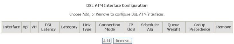
ATM Interface
The ATM PVC Configuration window allows you to set up ATM PVC configuration. Enter Virtual Path Identifier, and Virtual Channel Identifier. The VPI and VCI values should be provided by your ISP. This window also allows you to select DSL Link Type, PPPoA, IpoA and EoA (EoA is for PPPoE, IPOE, and Bridge)
Use the drop-down menu to select the desired Encapsulation Mode...
Click the Apply / Save button to Save.
ATM PVC Configuration
This screen allows you to configure an ATM PVC identifier (VPI and VCI), select DSL latency, select a service categoryS. Otherwise choose an existing interface by selecting the checkbox to enable it.
| VPI: [0-255] | 0 |
| VCI: [32-65535] | 35 |
Select DSL Latency
Path0
Path1
Select DSL Link Type (EoA is for PPPoE, IPoE, and Bridge.)
EoA
PPPoA
IPOA
Select Connection Mode
Default Mode - Single service over one connection
VLAN MUX Mode - Multiple Vlan service over one connection
Encapsulation Mode:
LLC/SNAP-BRIDGING
Service Category:
UBR Without PCR
Select IP QoS Scheduler Algorithm
Strict Priority
Precedence of the default queue:
8 (lowest)
Weighted Fair Queuing
Weight Value of the default queue: [1-63]

MPAAL Group Precedence:

Apply/Save
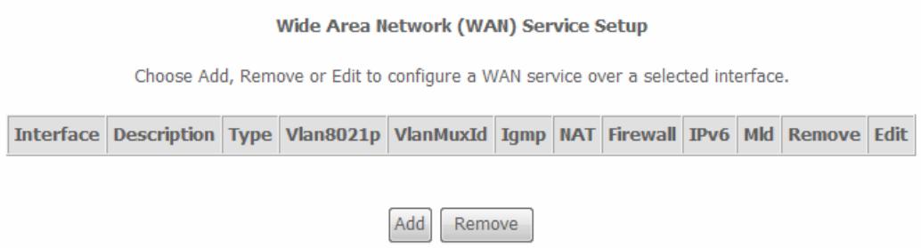
WAN Service
To access the Wide Area Network (WAN) Service Setup window, click the WAN Service button in the Advanced Setup directory.
This window is used to configure the WAN interface. You can add and delete WAN interface on this window.
If you are setting up the WAN interface for the first time, click the Add button.
The WAN Service Interface Configuration Configuration window allows select a layer 2 interface for this service. Click the Next button to continue.
WAN Service Interface Configuration
Select a layer 2 interface for this service
Note: For ATM interface, the descriptor string is (portId_vpi_vci)
For PTM interface, the descriptor string is (portId_high_low)
Where portId=0-->DSL Latency PATH0
portId=1-->DSL Latency PATH1
portId=4-->DSL Latency PATH0&1
low =0-->Low PTM Priority not set
low =1-->Low PTM Priority set
high =0-->High PTM Priority not set
high =1-->High PTM Priority set
atm0/(0_0_35)
Back Next
This window allows you to select the appropriate connection type. The choices include PPP over ATM (PPPPoA), PPP over Ethernet (PPPoE), IP over Ethernet (IpoE), IP over ATM (IPoA), and Bridging.
WAN Service Configuration - PPPoE
Click the PPP over Ethernet (PPPoE) radio button on this window. This window also allows you to use the drop-down menu to enable IPv6 service. Click the Next button to continue.
WAN Service Configuration
Select WAN service type:
PPP over Ethernet (PPPoE)
IP over Ethernet
Bridging
Enter Service Description: pppoe_0_0_35
Enable IPv6 for this service

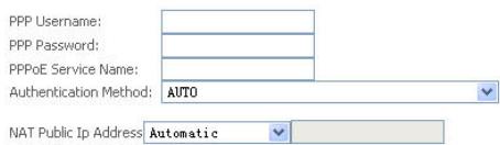
WAN Service Configuration - PPPoE
This window allows you to set the username and the password for your PPP connection. This information is obtained from your ISP. Additional settings on this window will also depend on your ISP. And You can input 2^nd ip on this page. Click the Next button to continue.
PPPUsername and Password
PPs uily requires that you have a user name and password to establish your connection. In the boxes below, enter the user name and password that your ISP has provided to you.
Dial on demand (with idle timeout timer)
□ enable manual MTU set
PPP IP extension
Use Static IPv4 Address
Enable PPP Debug Mode
Enable KeepAlive
Max Fail [0-100]: 0 times
Bridge PPPoE Frames Between WAN and Local Ports
Multicast Proxy
EnableIGMPMulticastProxy

WAN Service Configuration - PPPoE
Default gateway interface list can have multiple WAN interfaces served as system default gateways but only one will be used according to the priority with the first being the higest and the last one the lowest priority if the WAN interface is connected. Priority order can be changed by removing all and adding them back in again. Click the Next button to continue.
WAN Service Configuration - PPPoE
Select DNS Server Interface from available WAN interfaces OR enter static DNS server IP addresses for the system. In ATM mode, if only a single PVC with IPOA or static IPOE protocol is configured, Static DNS server IP addresses must be entered.
DNS Server Interfaces can have multiple WAN interfaces served as system dns servers but only one will be used according to the priority with the first being the higest and the last one the lowest priority if the WAN interface is connected. Priority order can be changed by removing all and adding them back in again. Click the Next button to continue
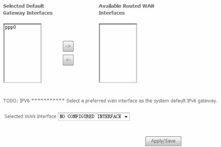
Routing -- Default Gateway
Default gateway interface list can have multiple WAN interfaces served as system default gateways but only one will be used according to the priority with the first being the highest and the last one the lowest priority if the WAN interface is connected. Priority order can be changed by removing all and adding them back in again.
Selected Default
Gateway Interfaces
Available Routed WAN
Interfaces


ck Next
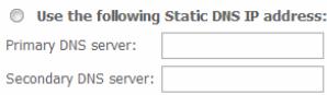
DNS Server Configuration
Select DNS Server Interface from available WAN interfaces OR enter static DNS server IP addresses for the system. In ATM mode, if only a single PVC with IPOA or static IPOE protocol is configured, Static DNS server IP addresses must be entered.
DNS Server Interfaces can have multiple WAN interfaces served as system dns servers but only one will be used according to the priority with the first being the highest and the last one the lowest priority if the WAN interface is connected. Priority order can be changed by removing all and adding them back in again.
Select DNS Server Interface from available WAN interfaces:
Selected DNS Server Interfaces
Available WAN Interfaces


Use the following Static DNS IP address:
Primary DNS server:
Secondary DNS server:
WAN Service Configuration - PPPoE
This summary window allows you to confirm the settings you have just made. Click the Apply / Save button to save your new PPP over Ethernet settings and restart the Router.
WAN Setup - Summary
Make sure that the settings below match the settings provided by your ISP.
| Connection Type: | PPPoE |
| NAT: | Enabled |
| Full Cone NAT: | Disabled |
| Firewall: | Enabled |
| IGMP Multicast: | Disabled |
| Quality Of Service: | Enabled |
Click "Apply/Save" to have this interface to be effective. Click "Back" to make any modifications.
Back Apply/Save
WAN Service Configuration - IPOE
Click the IP over Ethernet radio button on this window. Click the Next button to continue.
WAN Service Configuration
Select WAN service type:
PPP over Ethernet (PPPoE)
IP over Ethernet
Bridging
Enter Service Description: pppee_0_0_35
Enable IPv6 for this service

WAN Service Configuration - IPOE
This window allows you to configure the WAN IP settings. This information is obtained from your ISP. Click the Next button to continue.
WAN IP Settings
Enter information provided to you by your ISP to configure the WAN IP settings.
Notice: If "Obtain an IP address automatically" is chosen, DHCP will be enabled for PVC in IPOE mode.
If "Use the following Static IP address" is chosen, enter the WAN IP address, subnet mask and interface gateway.
Obtain an IP address automatically
| Option 60 Vendor ID: | |
| Option 61 IAID: | (8 hexadecimal digits) |
| Option 61 DUID: | (hexadecimal digit) |
| Option 125: | Disable Enable |
Use the following Static IP address:
| WAN IP Address: |
| WAN Subnet Mask: |
| WAN gateway IP Address: |

WAN Service Configuration - IPOE
This window allows you to enable or disable Network Address Translation and a firewall for your Router. In addition, you can enable or disable IGMP multicasting. And You can input 2^nd ip on this page. Click the Next button to continue.
WAN Service Configuration - IPOE
Default gateway interface list can have multiple WAN interfaces served as system default gateways but only one will be used according to the priority with the first being the higest and the last one the lowest priority if the WAN interface is connected. Priority order can be changed by removing all and adding them back in again. Click the Next button to continue
Network Address Translation Settings
Network Address Translation (NAT) allows you to share one Wide Area Network (WAN) IP address for multiple computers on your Local Area Network (LAN).

Enable NAT
NAT Public Ip Address Automatic

Enable Firewall
IGMP Multicast

Enable IGMP Multicast


Routing -- Default Gateway
Default gateway interface list can have multiple WAN interfaces served as system default gateways but only one will be used according to the priority with the first being the highest and the last one the lowest priority if the WAN interface is connected. Priority order can be changed by removing all and adding them back in again.
Selected Default Gateway Interfaces


Available Routed WAN Interfaces


WAN Service Configuration - IPOE
Select DNS Server Interface from available WAN interfaces OR enter static DNS server IP addresses for the system. In ATM mode, if only a single PVC with IPOA or static IPOE protocol is configured, Static DNS server IP addresses must be entered.
DNS Server Interfaces can have multiple WAN interfaces served as system dns servers but only one will be used according to the priority with the first being the higest and the last one the lowest priority if the WAN interface is connected. Priority order can be changed by removing all and adding them back in again. Click the Next button to continue
WAN Service Configuration - IPOE
This summary window allows you to confirm the settings you have just made. Click the Apply / Save button to save your new IP over Ethernet settings and restart the Router.
DNS Server Configuration
Select DNS Server Interface from available WAN interfaces OR enter static DNS server IP addresses for the system. In ATM mode, if only a single PVC with IPOA or static IPOE protocol is configured, Static DNS server IP addresses must be entered.
DNS Server Interfaces can have multiple WAN interfaces served as system dns servers but only one will be used according to the priority with the first being the highest and the last one the lowest priority if the WAN interface is connected. Priority order can be changed by removing all and adding them back in again.
Select DNS Server Interface from available WAN interfaces:
Selected DNS Server Interfaces
Available WAN Interfaces


WAN Setup - Summary
Make sure that the settings below match the settings provided by your ISP.
| Connection Type: | IPoE |
| NAT: | Enabled |
| Full Cone NAT: | Disabled |
| Firewall: | Enabled |
| IGMP Multicast: | Disabled |
| Quality Of Service: | Disabled |
Click "Apply/Save" to have this interface to be effective. Click "Back" to make any modifications.
Back
Apply/Save
WAN Service Configuration - BRIDGING
Click the Bridge radio button on this window. Click the Next button to continue.
WAN Service Configuration
Select WAN service type:
PPP over Ethernet (PPPoE)
IP over Ethernet

Enter Service Description:br_0_0_35
Enable IPv6 for this service

Next
WAN Service Configuration - BRIDGING
This summary window allows you to confirm the bridging settings you have just made. Click the Apply /Save button to save your new bridging settings and restart the Router.
WAN Setup - Summary
Make sure that the settings below match the settings provided by your ISP.
| Connection Type: | Bridge |
| NAT: | Disabled |
| Full Cone NAT: | Disabled |
| Firewall: | Disabled |
| IGMP Multicast: | Not Applicable |
| Quality Of Service: | Enabled |
Click "Apply/Save" to have this interface to be effective. Click "Back" to make any modifications.
Back Apply/Save
WAN Service Configuration - PPPoA
This window allows you to enter service description. Click the Next button to continue.
WAN Service Configuration
Enter Service Description: pppoa_0_0_35
Back Next
WAN Service Configuration - PPPoA
This window allows you to set the username and the password for your PPP connection. This information is obtained from your ISP. Additional settings on this window will also depend on your ISP. And You can input 2^nd ip on this page. Click the Next button to continue.
PPPUsername and Password
PPs uily requires that you have a user name and password to establish your connection. In the boxes below, enter the user name and password that your ISP has provided to you.

Dial on demand (with idle timeout timer)
□ enable manual MTU set
PPP IP extension
Use Static IPv4 Address
Enable PPP Debug Mode
Enable KeepAlive
Max Fail [0-100]: 0 times
Bridge PPPoE Frames Between WAN and Local Ports
Multicast Proxy
EnableIGMPMulticastProxy
Back Next
WAN Service Configuration -PPPoA
Default gateway interface list can have multiple WAN interfaces served as system default gateways but only one will be used according to the priority with the first being the higest and the last one the lowest priority if the WAN interface is connected. Priority order can be changed by removing all and adding them back in again. Click the Next button to continue.
WAN Service Configuration - PPPoA
Select DNS Server Interface from available WAN interfaces OR enter static DNS server IP addresses for the system. In ATM mode, if only a single PVC with IPOA or static IPOE protocol is configured, Static DNS server IP addresses must be entered.
DNS Server Interfaces can have multiple WAN interfaces served as system dns servers but only one will be used according to the priority with the first being the higest and the last one the lowest priority if the WAN interface is connected. Priority order can be changed by removing all and adding them back in again. Click the Next button to continue
Routing -- Default Gateway
Default gateway interface list can have multiple WAN interfaces served as system default gateways but only one will be used according to the priority with the first being the highest and the last one the lowest priority if the WAN interface is connected. Priority order can be changed by removing all and adding them back in again.
Selected Default
Gateway Interfaces
Available Routed WAN
Interfaces


DNS Server Configuration
Select DNS Server Interface from available WAN interfaces OR enter static DNS server IP addresses for the system. In ATM mode, if only a single PVC with IPOA or static IPOE protocol is configured, Static DNS server IP addresses must be entered.
DnsServer Interfaces can have multiple WAN interfaces served as system dns servers but only one will be used according to the priority with the first being the highest and the last one the lowest priority if the WAN interface is connected. Priority order can be changed by removing all and adding them back in again.
Select DNS Server Interface from available WAN interfaces:
Selected DNS Server Interfaces
Available WAN Interfaces


Use the following Static DNS IP address:
Primary DNS server:
Secondary DNS server:
WAN Service Configuration - PPPoA
This summary window allows you to confirm the settings you have just made. Click the Apply / Save button to save your new PPP over ATM settings and restart the Router.
WAN Setup - Summary
Make sure that the settings below match the settings provided by your ISP.
| Connection Type: | PPPoA |
| NAT: | Enabled |
| Full Cone NAT: | Disabled |
| Firewall: | Enabled |
| IGMP Multicast: | Disabled |
| Quality Of Service: | Disabled |
Click "Apply/Save" to have this interface to be effective. Click "Back" to make any modifications.

Apply/Save
WAN Service Configuration - IPOA
This window allows you to enter service description. Click the Next button to continue.
WAN Service Configuration
Enter Service Description: ipoa_0_0_35

WAN Service Configuration - IPOA
This window allows you to configure the WAN IP settings. This information is obtained from your ISP. Click the Next button to continue.
WAN IP Settings
Enter information provided to you by your ISP to configure the WAN IP settings.
WAN IP Address: 192.168.2.5
WAN Subnet Mask: 255.255.255.0

WAN Service Configuration - IPOA
This window allows you to enable or disable Network Address Translation and a firewall for your Router. In addition, you can enable or disable IGMP multicasting. Click the Next button to continue.
WAN Service Configuration - IPOA
Default gateway interface list can have multiple WAN interfaces served as system default gateways but only one will be used according to the priority with the first being the higest and the last one the lowest priority if the WAN interface is connected. Priority order can be changed by removing all and adding them back in again. Click the Next button to continue.
Network Address Translation Settings
Network Address Translation (NAT) allows you to share one Wide Area Network (WAN) IP address for multiple computers on your Local Area Network (LAN).

Enable NAT
NAT Public Ip Address Automatic

Enable Firewall
IGMP Multicast

Enable IGMP Multicast


Routing -- Default Gateway
Default gateway interface list can have multiple WAN interfaces served as system default gateways but only one will be used according to the priority with the first being the highest and the last one the lowest priority if the WAN interface is connected. Priority order can be changed by removing all and adding them back in again.
Gateway Interfaces

Selected Default

Available Routed WAN
Interfaces


WAN Service Configuration - IPOA
Select DNS Server Interface from available WAN interfaces OR enter static DNS server IP addresses for the system. In ATM mode, if only a single PVC with IPOA or static IPOE protocol is configured, Static DNS server IP addresses must be entered.
DNS Server Interfaces can have multiple WAN interfaces served as system dns servers but only one will be used according to the priority with the first being the higest and the last one the lowest priority if the WAN interface is connected. Priority order can be changed by removing all and adding them back in again. Click the Next button to continue
WAN Service Configuration - IPOA
This summary window allows you to confirm the settings you have just made. Click the Save/Reboot button to save your new IP over ATM settings and restart the Router.
DNS Server Configuration
Select DNS Server Interface from available WAN interfaces OR enter static DNS server IP addresses for the system. In ATM mode, if only a single PVC with IpoA or static IpoE protocol is configured, Static DNS server IP addresses must be entered.
DNS Server Interfaces can have multiple WAN interfaces served as system dns servers but only one will be used according to the priority with the first being the highest and the last one the lowest priority if the VAN interface is connected. Priority order can be changed by removing all and adding them back in again.
Select DNS Server Interface from available WAN interfaces:
Selected DNS Server
Interfaces
Available WAN Interfaces


Use the following Static DNS IP address:
Primary DNS server:
Secondary DNS server:
WAN Setup - Summary
Make sure that the settings below match the settings provided by your ISP.
| Connection Type: | IPoA |
| NAT: | Enabled |
| Full Cone NAT: | Disabled |
| Firewall: | Disabled |
| IGMP Multicast: | Disabled |
| Quality Of Service: | Disabled |
Click "Apply/Save" to have this interface to be effective. Click "Back" to make any modifications.
Back
Apply/Save
LAN
You can configure the LAN IP address to suit your preference. Many users will find it convenient to use the default settings together with DHCP service to manage the IP settings for their private network. The IP address of the Router is the base address used for DHCP. In order to use the Router for DHCP on your LAN, the IP address pool used for DHCP must be compatible with the IP address of the Router. The IP addresses available in the DHCP IP address pool will change automatically if you change the IP address of the Router.
To access the Local Area Network (LAN) Setup window, click the LAN button in the Advanced Setup directory.
This window allows you to set up a LAN interface. When you are finished, click the Apply / Save button.
Local Area Network (LAN) Setup
Configure the DSL Router IP Address and Subnet Mask for LAN interface. Save button only saves the LAN configuration data. Save/Reboot button saves the LAN configuration data and reboot the router to make the new configuration effective.
IP Address:
192.168.1.1
Subnet Mask:
255.255.255.0

Enable UPnP

Enable IGMP Snooping
Standard Mode
Blocking Mode

Disable DHCP Server
Enable DHCP Server
Start IP Address:
192.168.1.2
End IP Address:
192.168.1.254
Subnet Mask:
255.255.255.0
Leased Time (hour):24
Static IP Lease List: Please click on Save/Reboot button to make the new configuration effective. (A maximum 32 entries can be configured)
MAC Address
Address Remove:
Add Entries
Remove Entries
Configure the second IP Address and Subnet Mask for LAN interface

To access the IPv6 LAN Auto Configuration window, click the IPv6 AutoConfig button in the LAN directory.
This window allows you to set up IPv6 LAN Auto Configuration. When you are finished, click the Apply / Save button.
IPv6 LAN Auto Configuration
Note: Stateful DHCPv6 is supported based on the assumption of prefix length less than 64. Interface ID does NOT support ZERO COMPRESSION":". Please enter the complete information. For example: Please enter "0:0:0:2" instead of":2".
Static LAN IPv6 Address Configuration
Interface Address (prefix length is required):
IPv6 LAN Applications
Enable DHCPv6 Server
Stateless
Stateful
Start interface ID: 0:0:0:2
End interface ID: 0:0:0:254
Leased Time (hour)
Enable RADVD
Enable MLD Snooping
Save/Apply
NAT
To access the Network Address Translation (NAT) Setup window, click the NAT button in the Advanced Setup directory. The NAT button appears when configuring WAN interface in PPPoA, PPPoE, IPOE or IPOA.
Virtual Servers
This window is used to configure virtual server. You can add, delete, and modify virtual server on this window.
If you are setting up the virtual server, click the Add button.
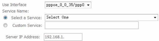
NAT - Virtual Servers Setup
Virtual Server allows you to direct incoming traffic from WAN side (Identified by Protocol and External port) to the Internal server with private IP address on the LAN side. The Internal port is required only if the external port needs to be converted to a different port number used by the server on the LAN side. A maximum 32 entries can be configured.
Add Remove
| Server Name | External Port Start | External Port End | Protocol | Internal Port Start | Internal Port End | Server IP Address | Remote Host | Remove |
You can configure the service settings on this window by clicking the Select a Service radio button and then using the drop-down list to choose an existing service, or by clicking the Custom Server radio button and entering your own Application Rule in the field provided.
Click Apply / Save when you are finished with the virtual server configuration.
NAT--Virtual Servers
Select the service name, and enter the server IP address and click "Apply/Save" to forward IP packets for this service to the specified server. NOTE: The "Internal Port End" cannot be modified directly. Normally, it is set to the same value as "External Port End". However, if you modify "Internal Port Start", then "Internal Port End" will be set to the same value as "Internal Port Start".
Remaining number of entries that can be configured:32
Apply/Save
| External Port Start | External Port End | Protocol | Internal Port Start | Internal Port End |
| TCP | ||||
| TCP | ||||
| TCP | ||||
| TCP | ||||
| TCP | ||||
| TCP | ||||
| TCP | ||||
| TCP | ||||
| TCP | ||||
| TCP | ||||
| TCP | ||||
| TCP | ||||
| TCP | ||||
Apply/Save
Port Triggering
Some applications such as games, video conferencing, remote access applications and others require that specific ports in the Router's firewall be opened for access by the applications. You can configure the port settings from this screen by selecting an existing application or creating your own (Custom application).
Click the Add button to configure port triggering.
NAT -- Port Triggering Setup
Some applications require that specific ports in the Router's firewall be opened for access by the remote parties. Port Trigger dynamically opens up the 'Open Ports' in the firewall when an application on the LAN initiates a TCP/UDP connection to a remote party using the 'Triggering Ports'. The Router allows the remote party from the WAN side to establish new connections back to the application on the LAN side using the 'Open Ports'. A maximum 32 entries can be configured.
Add Remove
| Application Name | Trigger | Open | WAN Interface | Remove | ||||
| Protocol | Port Range | Protocol | Port Range | |||||
| Start | End | Start | End | |||||
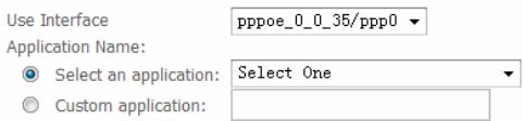
You can configure the port settings on this window by clicking the Select an application radio button and then using the drop-down list to choose an existing application, or by clicking the Custom application radio button and entering your own Application Rule in the field provided.
Click Save/Apply when you are finished with the port setting configuration. The new Application Rule will appear in the Port Triggering table.
NAT--Port Triggering
Some applications such as games, video conferencing, remote access applications and others require that specific ports in the Router's firewall be opened for access by the applications. You can configure the port settings from this screen by selecting an existing application or creating your own (Custom application)and click "Save/Apply" to add it.
Remaining number of entries that can be configured:32
Save/Apply
Save/Apply
DMZ Host
Since some applications are not compatible with NAT, the Router supports use of a DMZ IP address for a single host on the LAN. This IP address is not protected by NAT and will therefore be visible to agents on the Internet with the right type of software. Keep in mind that any client PC in the DMZ will be exposed to various types of security risks. If you use the DMZ, take measures (such as client-based virus protection) to protect the remaining client PCs on your LAN from possible contamination through the DMZ.
To designate a DMZ IP address, type in the IP Address of the server or device on your LAN, and click the Save/Apply button.
NAT--DMZ Host
The Broadband Router will forward IP packets from the WAN that do not belong to any of the applications configured in the Virtual Servers table to the DMZ host computer.
Enter the computer's IP address and click 'Apply' to activate the DMZ host.
Clear the IP address field and click 'Apply' to deactivate the DMZ host.
DMZ Host IP Address:

Save/Apply
Security
To access the Security window, click the Security button in the Advanced Setup directory. The Security button appears after configuring WAN interface in PPPoA, PPPoE, IPOE or IPOA.
IP Filtering
The IP Filtering button appears when configuring WAN interface in PPPoA, PPPoE, IPOE or IPOA.
IP Filtering - Outgoing
This window allows you to create a filter rule of Outgoing.
Click change default policy to change the mode of policy.
Now default policy is BLOCK, it means all outgoing IP traffic from LAN is blocked, but some IP traffic can be accepted by setting up filters.
If you are setting up the outgoing IP filtering, click the Add button.
Now default policy is ACCEPT, it means all outgoing IP traffic from LAN is allowed, but some IP traffic can be blocked by setting up filters.
If you are setting up the outgoing IP filtering, click the Add button.
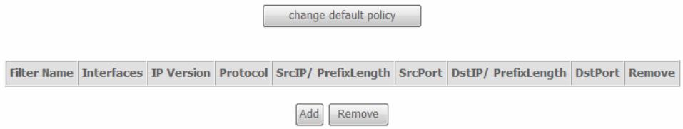
Outgoing IP Filtering Setup
By default, all outgoing IP traffic from LAN is allowed, but some IP traffic can be BLOCKED by setting up filters.
Choose Add or Remove to configure outgoing IP filters.
change default policy


Remove
Outgoing IP Filtering Setup
By default, all outgoing IP traffic from LAN is blocked, but some IP traffic can be ACCEPTED by setting up filters.
Choose Add or Remove to configure outgoing IP filters.
change default policy


Remove
Enter the information in the section. Explanations of parameters are described below. Click the Apply / Save button to add the entry in the Active Outbound IP Filtering table.
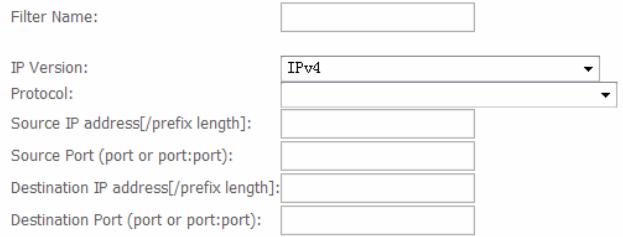
Add IP Filter -- Outgoing
The screen allows you to create a filter rule to identify outgoing IP traffic by specifying a new filter name and at least one condition below. All of the specified conditions in this filter rule must be satisfied for the rule to take effect. Click 'Apply/Save' to save and activate the filter.
Filter Name:
IP Version:
Protocol:
Source IP address[/prefix length]:
Source Port (port or port:port):
Destination IP address[/prefix length]:
Destination Port (port or port:port):
IPv4
Apply/Save
| Filters Parameter | Description |
| Filter Name | Enter a name for the new filter. |
| IP Version | IPv4/IPv6 |
| Protocol | Select the transport protocol (Any, TCP/UDP, TCP, UDP or ICMP) that will be used for the filter rule. |
| Source IP address[/prefix length] | Enter the start IP address which you are creating the filter rule. |
| Source Port (port or port:port) | The Source Port is the TCP/UDP port on either the LAN or WAN depending on if you are configuring an Outbound or Inbound Filter rule. |
| Destination IP address[/prefix length] | Enter the end IP address which you are creating the filter rule. |
| Destination Port (port or port:port) | The Destination Port is the TCP/UDP port on either the LAN or WAN depending on if you are configuring an Outbound or Inbound Filter rule. |
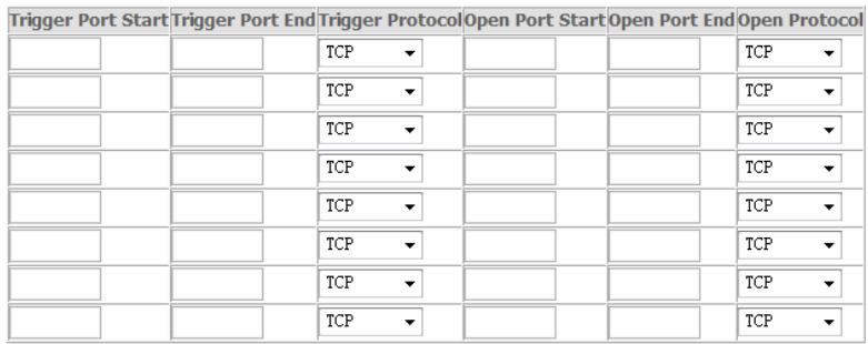
IP Filtering – Incoming
This window allows you to create a filter rule of Incoming. Click change default policy to change the mode of policy.
Now default policy is ACCEPT, it means all incoming IP traffic from WAN is accepted, but some IP traffic can be blocked by setting up filters.
If you are setting up the incoming IP filtering, click the Add button.
Now default policy is BLOCK, it means all incoming IP traffic from WAN is blocked, but some IP traffic can be accepted by setting up filters.
If you are setting up the incoming IP filtering, click the Add button.
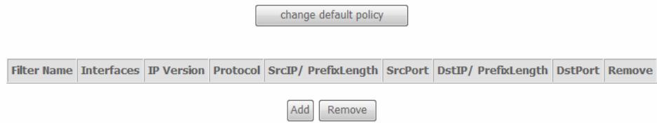
Incoming IP Filtering Setup
When the firewall is enabled on a WAN or LAN interface, all incoming IP traffic is blocked. However, some IP traffic can be ACCEPTED by setting up filters.
Choose Add or Remove to configure incoming IP filters.
Incoming IP Filtering Setup
When the firewall is enabled on a WAN or LAN interface, all incoming IP traffic is allowed. However, some IP traffic can be BLOCKED by setting up filters.
Choose Add or Remove to configure incoming IP filters.
Enter the information in the section. Explanations of parameters are described below. Click the Apply / Save button to add the entry in the Active Inbound IP Filtering table.
Add IP Filter--Incoming
The screen allows you to create a filter rule to identify incoming IP traffic by specifying a new filter name and at least one condition below. All of the specified conditions in this filter rule must be satisfied for the rule to take effect. Click 'Apply/Save' to save and activate the filter.
WAN Interfaces (Configured in Routing mode and with firewall enabled) and LAN Interfaces Select one or more WAN/LAN interfaces displayed below to apply this rule.
√ Select All
```c
pppoe_0_0_35/ppp0
br0/br0
Apply/Save
| Filters Parameter | Description |
| Filter Name | Enter a name for the new filter. |
| IP Version | IPv4/IPv6 |
| Protocol | Select the transport protocol (Any, TCP/UDP, TCP, UDP or ICMP) that will be used for the filter rule. |
| Source IP address[/prefix length] | Enter the start IP address which you are creating the filter rule. |
| Source Port (port or port:port) | The Source Port is the TCP/UDP port on either the LAN or WAN depending on if you are configuring an Outbound or Inbound Filter rule. |
| Destination IP address[/prefix length] | Enter the end IP address which you are creating the filter rule. |
| Destination Port | The Destination Port is the TCP/UDP port on either the LAN or WAN depending on if you are configuring an Outbound or |
(ports or port:port) Inbound Filter rule.
Parental Control
Use this window to deny access to specified MAC address.
If you are setting up the MAC address blocking, click the Add button.
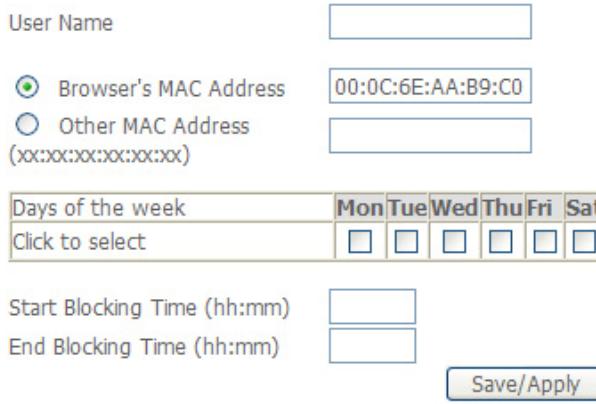
MAC address is a specially formatted text string (xx:xx:xx:xx:xx:xx) that uniquely identification of a device. This section will allow users to block devices with certain MAC addresses on the LAN.
To configure for MAC address blocking, enter the username into theUsername field, click Browser's MAC Address to have MAC address of the LAN device, or click Other MAC Address and enter a MAC address manually. Tick the checkboxes for the desired individual days of the week and enter desired Start Blocking Time and End Blocking Time.
Click the Save/Apply button to save the configuration
Time of Day Restrictions -- A maximum 16 entries can be configured.
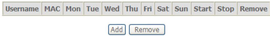
Time of Day Restriction
This page adds time of day restriction to a special LAN device connected to the Router. The 'Browser's MAC Address' automatically displays the MAC address of the LAN device where the browser is running. To restrict other LAN device, click the "Other MAC Address" button and enter the MAC address of the other LAN device. To find out the MAC address of a Windows based PC, go to command window and type "ipconfig /all".
URL Filter
This window allows you to set up URL Filter on the Router.
Choose URL List Type Exclude or Include first and click Add button.
URL Filter -- Please select the list type first then configure the list entries. Maximum 100 entries can be configured.
Exclude -- Deny computers to access the following web sites in the list.
Include -- Allow computers to access only the following sites in the list.
URL List Type: Exclude Include
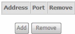
Enter the URL address and port number then click Apply / Save to add the entry to the URL filter.
Parental Control -- URL Filter Add
Enter the URL address and port number then click "Apply/Save" to add the entry to the URL filter.
URL Address:
Port Number:

(Default 80 will be applied if leave blank.)
Apply/Save
Quality of Service
QoS or Quality of Service allows your Router to help prioritize the data packet flow in your Router and network. This is very important for time sensitive applications such as VoIP where it may help prevent dropped calls. Large amounts of non-critical data can be scaled so as not to affect these prioritized sensitive real-time programs.
To access the QoS - Queue Management Configuration window, click the Quality of Service button in the Advanced Setup directory.
This window allows you to set up QoS on the Router. When you are finished, click on the Save/Apply button.
QoS - Queue Management Configuration
If Enable QoS checkbox is selected, choose a default DSCP mark to automatically mark incoming traffic without reference to a particular classifier. Click 'Save/Apply' button to save it.
Note: If Enable QoS checkbox is not selected, all QoS will be disabled for all interfaces.
Note: The default DSCP mark is used to mark all egress packets that do not match any classification rules.

Enable QoS
Select Default DSCP Mark
No Change(-1)


Save/Apply
Queue Config
Click the Add button to add a QoS Queue Configuration table entry.
QoS Queue Setup
In ATM mode, maximum 16 queues can be configured.
In PTM mode, maximum 8 queues can be configured.
For each Ethernet interface, maximum 4 queues can be configured.
| Name | Key | Interface | Scheduler Alg | Precedence | Weight | DSL Latency | PTM Priority | Enable | Remove |
| Default Queue | 40 | atm0 | SP | 8 | Path0 | ☐ |
This window allows you to configure a QoS queue entry and assign it a specific network interface.
Click the Apply / Save button to save and activate the filter.

QoS Queue Configuration
This screen allows you to configure a QoS queue and assign it to a specific layer2 interface. The scheduler algorithm is defined by the layer2 interface.
Note: For SP scheduling, queues assigned to the same layer2 interface shall have unique precedence. Lower precedence value implies higher priority for this queue relative to others
Click 'Apply/Save' to save and activate the queue.

QoS Classification
Choose Add or Remove to configure network traffic classes.
Use this window to create a traffic class rule to classify the upstream traffic, assign a queue that defines the precedence and the interface, and optionally overwrite the IP header DSCP byte. A rule consists of a class name and at least one condition. Please remember that all of the specified conditions on this window must be met for the rule to take effect.
Click the Apply / Save button to save and activate this rule.
QoS Classification Setup -- A maximum 32 entries can be configured.
Choose Add or Remove to configure network traffic classes.
| CLASSIFICATION CRITERIA | CLASSIFICATION RESULTS | |||||||||||||||||||
| Class Name | Order | Class Intf | Ether Type | SrcMAC/ Mask | DstMAC/ Mask | SrcIP/ PrefixLength | DstIP/ PrefixLength | Proto | SrcPort | DstPort | DSCP Check | 802.1P Check | Queue Key | DSCP Mark | 802.1P Mark | VlanID Tag | Rate Control (kbps) | Enable | Remove | |
| Add Enable Remove | ||||||||||||||||||||
Add Network Traffic Class Rule
The screen creates a traffic class rule to classify the upstream traffic, assign queue which defines the precedence and the interface and optionally overwrite the IP header DSCP byte. A rule consists of a class name and at least one condition below. All of the specified conditions in this classification rule must be satisfied for the rule to take effect. Click 'Apply/Save' to save and activate the rule.
Traffic Class Name:
Rule Order:
Rule Status:
Specify Classification Criteria
A blank criterion indicates it is not used for classification.
Class Interface:
Ether Type:
Source MAC Address:
Source MAC Mask:
Destination MAC Address:
Destination MAC Mask:
Specify Classification Results
Must select a classification queue. A blank mark or tag value means no change.
Assign Classification Queue:
Mark Differentiated Service Code Point (DSCP):
Mark 802.1p priority:
Tag VLAN ID [0-4094]:
Apply/Save
Routing
To access the Routing windows, click the Routing button in the Advanced Setup directory.
Default Gateway
Default gateway interface list can have multiple WAN interfaces served as system default gateways but only one will be used according to the priority with the first being the highest and the last one the lowest priority if the WAN interface is connected. Priority order can be changed by removing all and adding them back in again. Click the Apply / Save button when you are finished.
Routing--Default Gateway
Default gateway interface list can have multiple WAN interfaces served as system default gateways but only one will be used according to the priority with the first being the highest and the last one the lowest priority if the WAN interface is connected. Priority order can be changed by removing all and adding them back in again.
Static Route
Click the Add button on the Routing - Static Route window to access the following window displayed on the next page.
Routing -- Static Route (A maximum 32 entries can be configured)
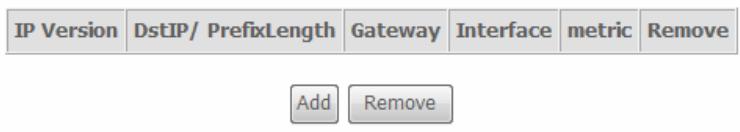
Enter the static routing information for an entry to the routing table.
Click the Apply / Save button when you are finished.
Routing--Static Route Add
Enter the destination network address, subnet mask, gateway AND/OR available WAN interface then click "Apply/Save" to add the entry to the routing table.
IP Version:
Destination IP address/regex length:
Interface:
Gateway IP Address:
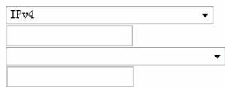
(optional: metric number should be greater than or equal to zero)
Metric:
Policy Routing
Click the Add button on the Policy Routing Setup window to access the following window displayed on the next page.
Policy Routing Setting -- A maximum 8 entries can be configured.
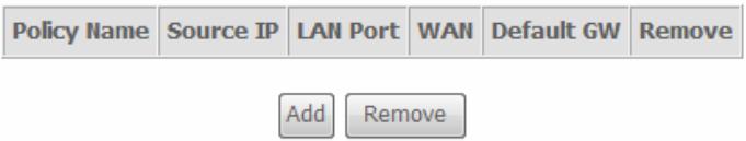
Enter the Policy Routing information.Click the Apply / Save button when you are finished.
Policy Routing Setup
Enter the policy name, policies, and WAN interface then click "Apply/Save" to add the entry to the policy routing table.
Note: If selected "IPoE" as WAN interface, default gateway must be configured.
Policy Name:
Physical LAN Port:
Source IP:
Use Interface pppee_0_0_35/ppp0
Default Gateway:
Apply/Save
RIP
To activate RIP for the device, select the Enabled radio button for Global RIP Mode. To configure an individual interface, select the desired RIP version and operation, followed by placing a check in the 'Enabled' checkbox for the interface. Click the Save/Apply button to save the configuration, and to start or stop RIP based on the Global RIP mode selected.
Routing - RIP Configuration
NOTE: RIP CANNOT BE CONFIGURED on the WAN interface which has NAT enabled (such as PPPoE).
To activate RIP for the WAN Interface, select the desired RIP version and operation and place a check in the 'Enabled' checkbox. To stop RIP on the WAN Interface, uncheck the 'Enabled' checkbox. Click the 'Apply/Save' button to star/stop RIP and save the configuration.
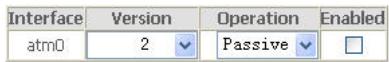
Apply/Save
DNS
To access the DNS windows, click the DNS button in the Advanced Setup directory. The DNS button appears when configuring WAN interface in PPPoA, PPPoE, MER or IPOA.
DNS Server
Select DNS Server Interface from available WAN interfaces OR enter static DNS server IP addresses for the system. In ATM mode, if only a single PVC with IPOA or static IPOE protocol is configured, Static DNS server IP addresses must be entered.
DNS Server Interfaces can have multiple WAN interfaces served as system dns servers but only one will be used according to the priority with the first being the higest and the last one the lowest priority if the WAN interface is connected. Priority order can be changed by removing all and adding them back in again. Click the Apply / Save button when you are finished.
DNS Server Configuration
Select DNS Server Interface from available WAN interfaces OR enter static DNS server IP addresses for the system. In ATM mode, if only a single PVC with IPOA or static IPOe protocol is configured, Static DNS server IP addresses must be entered.
DnsServer Interfaces can have multiple WAN interfaces served as system dns servers but only one will be used according to the priority with the first being the highest and the last one the lowest priority if the WAN interface is connected. Priority order can be changed by removing all and adding them back in again.
Select DNS Server Interface from available WAN interfaces
Selected DNS Server Interfaces


Available WAN Interfaces
Use the following Static DNS IP address:
Primary DNS server:
Secondary DNS server
TODO: IPv6请选择 the configured WAN interface for IPv6 DNS server information OR enter the static IPv6 DNS server Addresses. Note that selecting a WAN interface for IPv6 DNS server will enable DHCPv6 Client on that interface.
Obtain IPv6 DNS info from a WAN interface. WAN Interface selected: NO CONFIGURED IN
Use the following Static IPv6 DNS address
Primary 1Pv6 DNS server: Secondary 1Pv6 DNS server
0.0.0.0
Secondary IPv6 DNS server
0.0.0.0
Apply/Save
Dynamic DNS
The Router supports Dynamic DNS (Dynamic Domain Name Service). The Dynamic DNS service allows a dynamic public IP address to be associated with a static host name in any of the many domains, allowing access to a specified host from various locations on the Internet. This is enabled to allow remote access to a host by clicking a hyperlinked URL in the form hostname.dyndns.org. Many ISPs assign public IP addresses using DHCP, this can make it difficult to locate a specific host on the LAN using standard DNS. If for example you are running a public web server or VPN server on your LAN, this ensures that the host can be located from the Internet if the public IP address changes. DDNS requires that an account be setup with one of the supported DDNS providers.
Click Add to see the Add DDNS Settings section.
Dynamic DNS
The Dynamic DNS service allows you to alias a dynamic IP address to a static hostname in any of the many domains, allowing your DSL router to be more easily accessed from various locations on the Internet.
Choose Add or Remove to configure Dynamic DNS.
Enter the required DDNS information, click the Apply / Save button to save the information.

Note
DDNS requires that an account be setup with one of the supported DDNS servers prior to engaging it on the Router. This function will not work without an accepted account with a DDNS server.
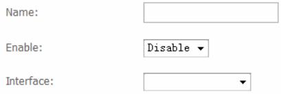
Add Dynamic DNS
This page allows you to add a Dynamic DNS address from DynDNS.org or TZO.
D-DNS provider
DynDNS.org
Hostname
Interface
pppoe_0_0_35/ppp0
DynDNS Settings
Username
Password
Apply/Save
DSL
To access the DSL Settings window, click the DSL button in the Advanced Setup directory.
This window allows you to select the desired modulation, phone line pair, and capability. Click the Apply / Save button when you are finished.
Click the Advanced Settings button to select a DSL test mode.
Note: Modulation ADSL2、ADSL2+ and AnnexL should be selected simultaneously
DSL Settings
Select the modulation below.
G.Dmt Enabled
T1.413 Enabled
ADSL2 Enabled
AnnexL Enabled
ADSL2+Enabled
AnnexM Enabled
Capability
- Bitswap Enable
SRA Enable
Apply/Save
Advanced Settings
Select the desired DSL test mode and then click the Apply button.
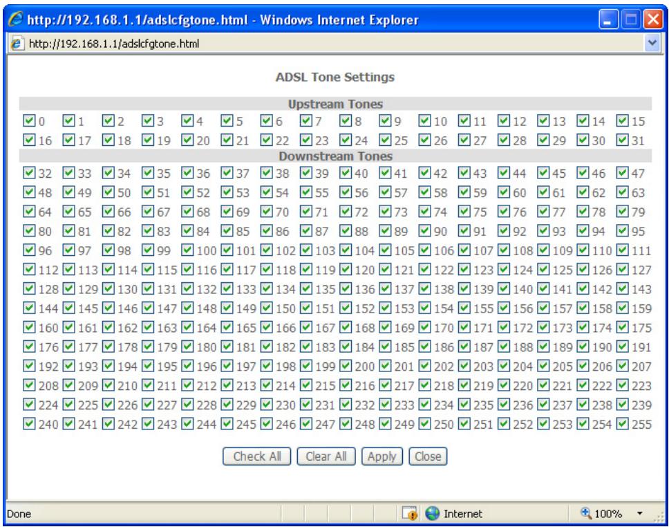
Click the Tone Selection button to modify the upstream and downstream tones.
DSL Advanced Settings
Select the test mode below.
Normal
Reverb
Medley
No retrain
L3
Apply Tone Selection
Select the appropriate upstream and downstream tones for your ADSL connection. Click the Apply button to let your settings take effect.
UPNP
To access the UPnP Configuration window, click the UPnP button in the Advanced Setup directory.
This window allows you to Config UPnP Proxy. Click the Apply / Save button when you are finished.
UPnP Configuration
NOTE: UPnP is activated only when there is a live WAN service with NAT enabled.
Enable UPnP
Apply/Save
DNS Proxy
To access the DNS Proxy Configuration window, click the DNS Proxy button in the Advanced Setup directory.
This window allows you to Config DNS Proxy. Click the Apply / Save button when you are finished.
DNS Proxy Configuration
Enable DNS Proxy
Host name of the Broadband Router:
Broadcom
Domain name of the LAN network:
Home
Apply/Save
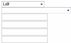
Interface Group
Interface Group supports multiple ports to PVC and bridging groups. Each group will perform as an independent network.
To support this feature, you must create mapping groups with appropriate LAN and WAN interfaces using the Add button. The Remove button will remove the grouping and add the ungrouped interfaces to the Default group. Only the default group has IP interface.
Click Add to do advanced settings.
Interface Grouping - A maximum 16 entries can be configured
Interface Grouping supports multiple ports to PVC and bridging groups. Each group will perform as an independent network. To support this feature, you must create mapping groups with appropriate LAN and WAN interfaces using the Add button. The Remove button will remove the grouping and add the ungrouped interfaces to the Default group. Only the default group has IP interface.
| Group Name | Remove | WAN Interface | LAN Interfaces | DHCP Vendor IDs |
| Default | LAN4 | |||
| LAN3 | ||||
| LAN2 | ||||
| LAN1 | ||||
| wlan0 |
Add Remove
To create a new mapping group, enter Group Name, add interfaces to Grouped Interfaces.
Click Apply / Save to save the changes.
Interface grouping Configuration
To create a new interface group:
1. Enter the Group name and the group name must be unique and select either 2. (dynamic) or 3. (static) below:
2, if you like to automatically add LAN clients to a WAN Interface in the new group add the DHCP vendor ID string, by configuring a DHCP vendor ID string any DHCP client request with the specified vendor ID (DHCP option 60) will be denied an IP address from the local DHCP server.
3. Select interfaces from the available interface list and add it to the grouped interface list using the arrow buttons to create the required mapping of the ports. Note that these clients may obtain public IP addresses
4. Click Apply/Save button to make the changes effective immediately
I i t

Grouped LAN Interfaces


Available LAN Interfaces

Automatically Add Clients With the Following DHCP Vendor IDS

Apply/Save
IPSec
To access the IPSec Tunnel Mode Connections window, click the IPSec button in the Advanced Setup directory.
This window allows you to configure IPSec.
Click Add New Connection to edit IPSec tunnel mode connections from this page
IPSec Tunnel Mode Connections
Add, remove or enable/disable IPSec tunnel connections from this page.
Connection Name Remote Gateway Local Addresses Remote Addresses Remove
Add New Connection Remove
This window allows you to advanced settings.
IPSec Settings
IPSec Connection Name
Tunnel Mode
Remote IPSec Gateway Address (IPv4 address in dotted decimal)
Tunnel access from local IP addresses
IP Address for VPN
IP Subnetmask
Tunnel access from remote IP addresses
IP Address for VPN
IP Subnetmask
Key Exchange Method
Authentication Method
Pre-Shared Key
Perfect Forward Secrecy
Advanced IKE Settings
new connection
ESP
0.0.0.0
Subnet
0.0.0.0
255.255.255.0
Subnet
0.0.0.0
255.255.255.0
Auto(I
Pre-Shared Key
key
Disable
Show Advanced Settings
Apply/Save
Multicast
To access the IGMP Configuration window, click the Multicast button in the Advanced Setup directory.
Enter IGMP protocol configuration fields if you want modify default values shown below.
IGMP Configuration
Enter IGMP protocol configuration fields if you want modify default values shown below.
| Default Version: | 3 |
| Query Interval: | 125 |
| Query Response Interval: | 10 |
| Last Member Query Interval: | 10 |
| Robustness Value: | 2 |
| Maximum Multicast Groups: | 25 |
| Maximum Multicast Data Sources (for IGMPv3 : (1 - 24)): | 10 |
| Maximum Multicast Group Members: | 25 |
| Fast Leave Enable: | √ |
| LAN to LAN (Intra LAN) Multicast Enable: | √ |
Apply/Save
Wireless
Press Wireless in the left menu to enter wireless section. You can select to configure wireless setup, security and management.
Basic
This page allows you to configure basic features of the wireless LAN interface. You can enable or disable the wireless LAN interface, hide the network from active scans, set the wireless network name (also known as SSID) and restrict the channel set based on country requirements. Click "Apply/Save" to configure the basic wireless options.
Wireless -- Basic
This page allows you to configure basic features of the wireless LAN interface. You can enable or disable the wireless LAN interface, hide the network from active scans, set the wireless network name (also known as SSID) and restrict the channel set based on country requirements.
Click "Apply/Save" to configure the basic wireless options.
Enable Wireless
Hide Access Point
Clients Isolation
Enable Wireless Multicast Forwarding (WMF)
SSID: DLin
BSSID: 00:22:33:44:55:67
Country: UNI
Max Clients: 16
Wireless - Guest/Virtual Access Points:
| Enabled | SSID | Hidden | Isolate Clients | Enable WMF | Max Clients | BSSID |
| □ | DLink0_Guest1 | □ | □ | □ | 16 | N/A |
| □ | DLink0_Guest2 | □ | □ | □ | 16 | N/A |
| □ | DLink0_Guest3 | □ | □ | □ | 16 | N/A |
Apply/Save
This page allows you to configure security features of the wireless LAN interface.
You may setup configuration manually or through WiFi Protected Setup(WPS)
You can select to configure WEP encryption, Shared, 802.1x, WPA, and WPA2 authentication.
Security
Wireless -- Security
This page allows you to configure security features of the wireless LAN interface.
You may setup configuration manually
through WiFi Protected Setup(WPS)
WPS Setup
Enable WPS
Disabled
Manual Setup AP
You can set the network authentication method, selecting data encryption, specify whether a network key is required to authenticate to this wireless network and specify the encryption strength. Click "Apply/Save" when done.
Select SSID:
DLink
Network Authentication:
None
Apply/Save
MAC Filter
This page can help you to allow or deny certain MAC addresses to pass through or block out.
Click Add to see the following page.
Wireless -- MAC Filter
Select SSID: DLink
MAC Restrict Mode: Disabled Allow Deny
MAC Address Remove
Add
Remove
Enter MAC Address and click Apply / Save to add the MAC address to MAC filter.
Wireless -- MAC Filter
Enter the MAC address and click "Apply/Save" to add the MAC address to the wireless MAC address filters.
MAC Address:
Apply/Save
Wireless Bridge
This page allows you to configure bridge features of the wireless LAN.
Click Refresh to update the remote bridges.
Click Apply / Save to save the settings.
Wireless -- Bridge
This page allows you to configure wireless bridge features of the wireless LAN interface. You can select Wireless Bridge (also known as Wireless Distribution System) to disable access point functionality. Selecting Access Point enables access point functionality. Wireless bridge functionality will still be available and wireless stations will be able to associate to the AP. Select Disabled in Bridge Restrict which disables wireless bridge restriction. Any wireless bridge will be granted access. Selecting Enabled or Enabled(Scan) enables wireless bridge restriction. Only those bridges selected in Remote Bridges will be granted access.
Click "Refresh" to update the remote bridges. Wait for few seconds to update.
Click "Apply/Save" to configure the wireless bridge options.
AP Mode:
Bridge Restrict:

Remote Bridges MAC Address:
Refresh
Apply/Save
Advanced
This page allows you to configure advanced wireless LAN interface. Configuring these settings may increase the performance of your router but if you are not familiar with networking devices and protocols, this section should be left at its default settings. Click Apply / Save to save the settings.
Wireless--Advanced
This page allows you to configure advanced features of the wireless LAN interface. You can select a particular channel on which to operate, force the transmission rate to a particular speed, set the fragmentation threshold, set the RTS threshold, set the wakeup interval for clients in power-save mode, set the beacon interval for the access point, set XPress mode and set whether short or long preambles are used. Click "Apply/Save" to configure the advanced wireless options.

Apply/Save
Station Info
This page shows the authenticated wireless stations and their status. Click Refresh to update the information.
Wireless -Authenticated Stations
This page shows authenticated wireless stations and their status.
| MAC | Associated | SSID | Interface |
| 00:23:4E:CE:EC:44 | DLink | w10 |
Refresh
Diagnostics
Your modem is capable of testing your DSL connection with access to Diagnostics.
This window is used to test connectivity of the Router.
Your modem is capable of testing your DSL connection. The individual tests are listed below. If a test displays a fail status, click: "Rerun Diagnostic Tests" at the bottom of this page to make sure the fail status is consistent. If the test continues to fail, click: "Help" and follow the troubleshooting procedures.
Test the connection to your local network
| Test your LAN4 Connection: | PASS | Help |
| Test your LAN3 Connection: | FAIL | Help |
| Test your LAN2 Connection: | FAIL | Help |
| Test your LAN1 Connection: | PASS | Help |
| Test your Wireless Connection: | PASS | Help |
Test the connection to your DSL service provider
| Test aDSL Synchronization: | FAIL | Help |
| Test ATM GAM F5 segment ping: | DISABLED | Help |
| Test ATM GAM F5 end-to-end ping: | DISABLED | Help |
Test the connection to your Internet service provider
| Ping default gateway: | FAIL | Help |
| Ping primary Domain Name Server: | FAIL | Help |

Test With OAM F4
Management
The Management directory features an array of options designed to help you get the most out of your Router.
Settings
To access the Settings - Backup window, click the Settings button in the Management directory.
This window allows you to backup your DSL Router configurations.
Click the Backup Settings button to save your Router configurations to a file on your computer.
Settings-Backup
Backup DSL router configurations. You may save your router configurations to a file on your PC.
Backup Settings
This window allows Update DSL router settings. You may update your router settings using your saved files.
Click the Update Settings button to update your Router configurations with a file on your computer.
Tools--Update Settings
Update DSL router settings. You may update your router settings using your saved files.
Settings File Name:
浏览..
Update Settings
This window allows Restore DSL router settings to the factory defaults.
Click the Restore DSL Settings button to restore DSL router settings to the factory defaults.
Tools--Restore Default Settings
Restore DSL router settings to the factory defaults.
Restore Default Settings
System Log
These windows allow you to view the System Log and configure the System Log options. To access the System Log window, click the System Log button in the Management directory.
Click the View System Log button to view the System Log.
Click the Configure System Log button to configure the System Log options.
Click on the Refresh button to refresh the system log settings.
System Log - Configuration
The system log displays chronological event log data. The event log can be read from local host or sent to a System Log server. The available event severity levels are: Emergency, Alert, Critical, Error, Warning, Notice, Informational, and Debugging.
This window allows you to log selected events. When you are finished, click the Apply / Save button.
System Log
The System Log dialog allows you to view the System Log and configure the System Log options.
Click "View System Log" to view the System Log.
Click "Configure System Log" to configure the System Log options.
View System Log
Configure System Log
System Log
Date/Time Facility Severity Message
Refresh
Close
System Log -- Configuration
If the log mode is enabled, the system will begin to log all the selected events. For the Log Level, all events above or equal to the selected level will be logged. For the Display Level, all logged events above or equal to the selected level will be displayed. If the selected mode is 'Remote' or 'Both,' events will be sent to the specified IP address and UDP port of the remote syslog server. If the selected mode is 'Local' or 'Both,' events will be recorded in the local memory.
Select the desired values and click 'Apply/Save' to configure the system log options.
Log:

Disable

① Enable
Log Level:
Display Level:
Mode:

gging
。
.
Apply/Save
SNMP Agent
To access the SNMP - Configuration window, click the SNMP Agent button in the Management directory.
Simple Network Management Protocol allows a management application to retrieve statistics and status from the SNMP agent in the Router. When you are finished, click the Save/Apply button.
SNMP - Configuration
Simple Network Management Protocol (SNMP) allows a management application to retrieve statistics and status from the SNMP agent in this device.
Select the desired values and click "Apply" to configure the SNMP options.
SNMP Agent
Disable E
Read Community:
Set Community:
System Name:
System Location:
System Contact:
Trap Manager IP:
public
private
Broadcom
unknown
unknown
0.000
SaveApply
TR-069 Client
To access the TR-069 Client - Configuration window, click the TR-069 Client button in the Management directory.
Simple Network Management Protocol allows a management application to retrieve statistics and status from the TR-069 client in the Router. When you are finished, click the Save/Apply button.
TR-069 client - Configuration
WAN Management Protocol (TR-069) allows a Auto-Configuration Server (ACS) to perform auto-configuration, provision, collection, and diagnostics to this device.
Select the desired values and click "Apply/Save" to configure the TR-069 client options.
Inform
Inform Interval:
ACS URL:
ACS User Name:
ACS Password:
WAN Interface used by TR-069 client:
Display SOAP messages on serial console
Connection Request Authentication
Connection Request User Name:
Connection Request Password:
Connection Request URL:

Disable

Enable
300
admin
Any_WAN

isable

Enable
admin
Apply/Save
GetRPCMethods
Internet Time
To access the Time settings window, click the Internet Time button in the Management directory.
This window allows you to set the Router's time configuration. When you are finished, click the Save/Apply button.
Time settings
This page allows you to the modem's time configuration.
□ Automatically synchronize with Internet time servers
SaveApply
Access Control
To access the Access Control windows, click the Access Control button in the Management directory.
This window allows you to change the password on the Router. When you are finished, click the Save/Apply button.
Passwords
Access Control-- Passwords
Access to your broadband router is controlled through three user accounts: admin, support, and user.
The user name "admin" has unrestricted access to change and view configuration of your Broadband Router.
The user name "support" is used to allow an ISP technician to access your Broadband Router for maintenance and to run diagnostics.
The user name "user" can access the Broadband Router, view configuration settings and statistics, as well as, update the router's software.
Use the fields below to enter up to 16 characters and click "Apply/Save" to change or create passwords. Note: Password cannot contain a space.
UserID:
Old Password:
New Password:
Confirm Password:

Apply/Save
Update Software
To access the Tools - Update Software window, click the Update Software button in the Management directory.
This window allows you to update the Router's software.
Tools--Update Software
Step 1: Obtain an updated software image file from your ISP.
Step 2: Enter the path to the image file location in the box below or click the "Browse" button to locate the image file.
Step 3: Click the "Update Software" button once to upload the new image file.
NOTE: The update process takes about 2 minutes to complete, and your DSL Router will reboot.
Software File Name:
Browse.
Update Software
Reboot
To access this window, click the Reboot button in the Management directory.
To save your settings and reboot the system, click the Reboot button.
Click the button below to reboot the router.
Reboot
Troubleshooting
This chapter provides solutions to problems that might occur during the installation and operation of the DSL-2730U. Read the following descriptions if you are having problems. (The examples below are illustrated in Windows® XP. If you have a different operating system, the screenshots on your computer will look similar to the following examples.)
1. How do I configure my DSL-2730U Router without the CD-ROM?
- Connect your PC to the Router using an Ethernet cable.
- Open a web browser and enter the address http://192.168.1.1
- The default username is 'admin' and the default password is 'admin'.
- If you have changed the password and cannot remember it, you will need to reset the Router to the factory default setting (see question 2), which will set the password back to 'admin'.
Note: Please refer to the next section "Networking Basics" to check your PC's IP configuration if you can't see the login windows.
2. How do I reset my Router to the factory default settings?
- Ensure the Router is powered on.
- Press and hold the reset button on the back of the device for approximately 10 seconds.
This process should take around 30~60 seconds.
3. What can I do if my Router is not working correctly?
There are a few quick steps you can take to try and resolve any issues:
- Follow the directions in Question 2 to reset the Router.
- Check that all the cables are firmly connected at both ends.
- Check the LEDs on the front of the Router. The Power indicator should be on, the Status indicator should flash, and the DSL and LAN indicators should be on as well.
- Please ensure that the settings in the Web-based configuration manager, e.g. ISP username and password, are the same as the settings that have been provided by your ISP.
4. Why can't I get an Internet connection?
For ADSL ISP users, please contact your ISP to make sure the service has been enabled/connected by your ISP and that your ISP username and password are correct.
5. What can I do if my router can't be detected by running installation CD?
- Ensure the Router is powered on.
- Check that all the cables are firmly connected at both ends and all LEDs work correctly.
- Ensure only one network interface card on your PC is activated.
- Click on Start > Control Panel > Security Center to disable the setting of Firewall.
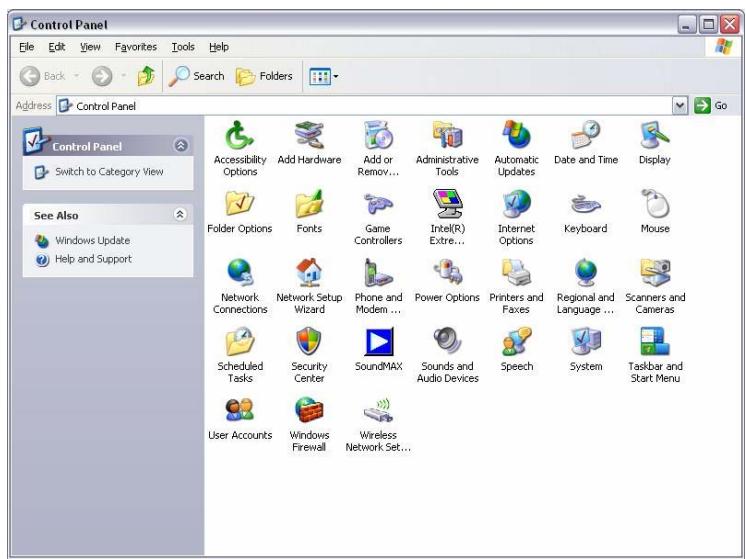
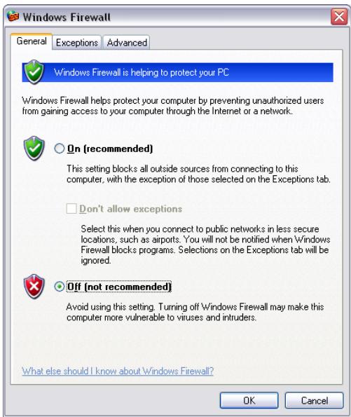
Note: There might be a potential security issue if you disable the setting of Firewall on your PC. Please remember to turn it back on once you have finished the whole installation procedure and can surf on Internet without any problem.
Networking Basics
Check Your IP Address
After you install your new D-Link adapter, by default, the TCP/IP settings should be set to obtain an IP address from a DHCP server (i.e. wireless router) automatically. To verify your IP address, please follow the steps below.
Click on Start > Run. In the run box type cmd and click on the OK.
At the prompt, type ipconfig and press Enter.
This will display the IP address, subnet mask, and the default gateway of your adapter.
If the address is 0.0.0.0, check your adapter installation, security settings, and the settings on your router. Some firewall software programs may block a DHCP request on newly installed adapters.
If you are connecting to a wireless network at a hotspot (e.g. hotel, coffee shop, airport), please contact an employee or administrator to verify their wireless network settings.
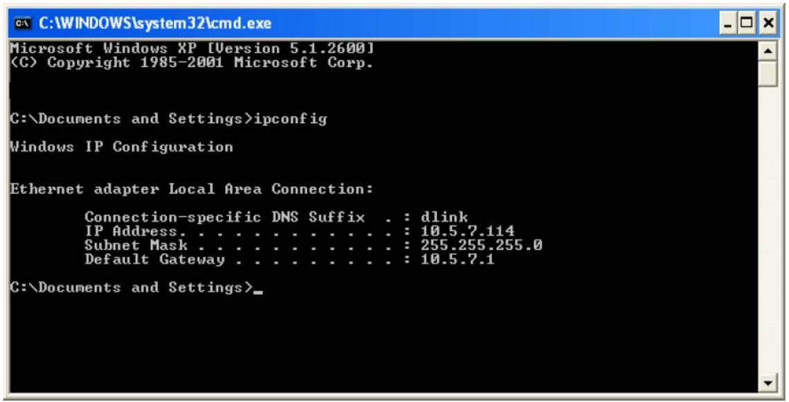
Statically Assign an IP Address
If your DHCP is disabled, or you need to assign a static IP address, please follow the steps below:
Step 1
Windows® XP - Click on Start > Control Panel > Network Connections.
Windows® 2000 - From the desktop, right-click on the My Network Places > Properties.
Step 2
Right-click on the Local Area Connection which represents your D-Link network adapter and select Properties.
Step 3
Highlight Internet Protocol (TCP/IP) and click on the Properties.
Step 4
Click on the Use the following IP address and enter an IP address that is on the same subnet as your network or the LAN IP address on your router.
Example: If the router's LAN IP address is 192.168.1.1, make your IP address 192.168.1.X where X is a number between 2 and 99. Make sure that the number you choose is not in use on the network. Set Default Gateway the same as the LAN IP address of your router (192.168.1.1).
Set Primary DNS the same as the LAN IP address of your router (192.168.1.1). The Secondary DNS is not needed or you may enter a DNS server from your ISP.
Step 5
Click on the OK twice to save your settings.
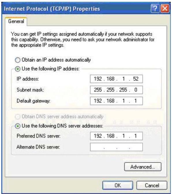
Technical Specifications
ADSL Standards
ANSI T1.413 Issue 2
ITU G.992.1 (G.dmt) AnnexA
ITU G.992.2 (G.lite) Annex A
ITU G.994.1 (G.hs)
ADSL2 Standards
ITU G.992.3 (G.dmt.bis) Annex A
ITU G.992.4 (G.lite.bis) Annex A
ADSL2+ Standards
ITU G.992.5 Annex A/M
Protocols
- IEEE 802.1d Spanning Tree
- TCP/UDP
ARP
RARP - ICMP
- RFC1058 RIP v1
- RFC1213 SNMP v1 & v2c
- RFC1334 PAP
- RFC1389 RIP v2
-
RFC1577 Classical IP over ATM
-
RFC1483/2684
Multiprotocol
Encapsulation over ATM
Adaptation Layer 5 (AAL5)
RFC1661 Point to Point Protocol - RFC1994 CHAP
- RFC2131 DHCP Client / DHCP Server
- RFC2364 PPP over ATM
- RFC2516 PPP over Ethernet
Data Transfer Rate
G.dmt full rate downstream: up to 8 Mbps / upstream: up to 1 Mbps
• G.lite: ADSL downstream up to 1.5 Mbps / upstream up to 512 Kbps
G.dmt.bis full rate downstream: up to 12 Mbps / upstream: up to 1 Mbps
- ADSL full rate downstream: up to 24 Mbps / upstream: up to 1 Mbps
Wireless Transfer Rates
- IEEE 802.11n: 6.5, 13, 19.5, 26, 39, 52, 58.5, 65, 78, 104, 117, 130 Mbps
- IEEE 802.11b: 11, 5.5, 2, and 1Mbps
- IEEE 802.11g: 6, 9, 12, 18, 24, 36, 48, 54Mbps
Media Interface
- ADSL interface: RJ-11 connector for connection to 24/26 AWG twisted pair telephone line
- LAN interface: RJ-45 port for 10/100BASE-T Ethernet connection
Certification:
- This device complies with Part15 of the FCC Rules. Operation is subject to the following conditions:
(1) This device may not cause harmful interference.
(2) This device must accept any interference received, including interference that may cause undesired operation.