
VL6 - Carte mère ABIT - Notice d'utilisation et mode d'emploi gratuit
Retrouvez gratuitement la notice de l'appareil VL6 ABIT au format PDF.

| Type de produit | Carte mère |
| Marque | ABIT |
| Modèle | VL6 |
| Facteur de forme | ATX |
| Dimensions | 305 x 190 mm |
| Socket CPU | Socket 370 (FC-PGA / PPGA) |
| Processeurs supportés | Intel Pentium III (500 MHz - 1 GHz), Intel Celeron (300A - 733 MHz) |
| Fréquence de bus FSB | 66, 100 ou 133 MHz |
| Chipset | VIA Apollo Pro 133 (VT82C693A + VT82C686A) |
| Type de mémoire | SDRAM PC100 / PC133 |
| Nombre de slots mémoire | 3 x DIMM 168 broches |
| Capacité mémoire maximale | 768 Mo (8 Mo à 256 Mo par module) |
| Support ECC | Oui |
| Slots d'extension | 1 AGP 2x, 5 PCI, 1 ISA, 1 AMR |
| Connecteurs de stockage | 2 x IDE (Ultra DMA 33/66), 1 x FDD |
| Ports USB | 2 ports USB arrière + en-tête pour 2 ports supplémentaires (total 4) |
| Audio intégré | AC'97 2.1 avec contrôleur Sound Blaster Pro |
| Ports d'E/S arrière | PS/2 clavier et souris, 2x COM, 1x parallèle, Line-in/out, MIC, MIDI/Game |
| Fonctions réseau | Wake-on-LAN, Wake-on-Modem (en-têtes) |
| Surveillance matérielle | Températures CPU et système, tensions, vitesses de ventilateurs |
| Alimentation requise | ATX, +5VSB ≥ 720 mA pour WoL/Modem |
| BIOS | Award Plug & Play, SOFT MENU™ II, protection antivirus Write-Protect |
FOIRE AUX QUESTIONS - VL6 ABIT
Questions des utilisateurs sur VL6 ABIT
0 question sur cet appareil. Repondez a celles que vous connaissez ou posez la votre.
Poser une nouvelle question sur cet appareil
Téléchargez la notice de votre Carte mère au format PDF gratuitement ! Retrouvez votre notice VL6 - ABIT et reprennez votre appareil électronique en main. Sur cette page sont publiés tous les documents nécessaires à l'utilisation de votre appareil VL6 de la marque ABIT.
MODE D'EMPLOI VL6 ABIT
Copyright and Warranty Notice
The information in this document is subject to change without notice and does not represent a commitment on part of the vendor, who assumes no liability or responsibility for any errors that may appear in this manual.
No warranty or representation, either expressed or implied, is made with respect to the quality, accuracy or fitness for any particular part of this document. In no event shall the manufacturer be liable for direct, indirect, special, incidental or consequential damages arising from any defect or error in this manual or product.
Product names appearing in this manual are for identification purpose only and trademarks and product names or brand names appearing in this document are the property of their respective owners.
This document contains materials protected under International Copyright Laws. All rights reserved. No part of this manual may be reproduced, transmitted or transcribed without the expressed written permission of the manufacturer and authors of this manual.
If you do not properly set the motherboard settings causing the motherboard to malfunction or fail, we cannot guarantee any responsibility.
VL6 Motherboard User's Manual
Index
CHAPTER 1. INTRODUCTION OF VL6 FEATURES 1-1
1-1. FEATURES OF THIS MOTHERBOARD 1-1
1-2. SPECIFICATIONS 1-2
1-3. LAYOUT DIAGRAM 1-3
1-4. THE SYSTEM BLOCK DIAGRAM 1-4
CHAPTER 2. INSTALLING THE MOTHERBOARD. 2-1
2-1. INSTALLING THE MOTHERBOARD TO THE CHASSIS 2-1
2-2. INSTALLATION OF THE INTEL® CELERON™ (PPGA & FC-PGA) & PENTIUM III (FC-PGA) PROCESSORS 2-2
2-3. INSTALLING SYSTEM MEMORY 2-3
2-4. CONNECTORS, HEADERS AND SWITCHES 2-4
CHAPTER 3. INTRODUCING THE BIOS 3-1
3-1. CPU SETUP [SOFT MENU™ II] 3-3
3-2. STANDARD CMOS FEATURES SETUP MENU 3-7
3-3. ADVANCED BIOS FEATURES SETUP MENU 3-11
3-4. ADVANCED CHIPSET FEATURES SETUP MENU 3-15
3-5. INTEGRATED PERIPHERALS 3-19
3-6. POWER MANAGEMENT SETUP MENU 3-23
3-7. PNP/PCI CONFIGURATIONS SETUP MENU 3-30
3-8. PC HEALTH STATUS 3-33
3-9. LOADFAIL-SAFEDEFAULTS 3-34
3-10. LOAD OPTIMIZED DEFAULTS 3-34
3-11. SET PASSWORD 3-35
3-12. SAVE & EXIT SETUP 3-37
3-13. EXIT WITHOUT SAVING 3-38
APPENDIX A. INSTALLING THE VIA SERVICE PACK DRIVERS FOR WINDOWS® 98 SE
APPENDIX B. INSTALLING THE VIA PCI AUDIO DRIVER FOR WINDOWS® 98 SE
APPENDIX C. INSTALLING THE VIA USB FILTER DRIVER FOR WINDOWS® 98 SE
APPENDIX D. INSTALLING THE VIA SERVICE PACK DRIVERS FOR WINDOWS® NT 4.0 SERVER/WORKSTATION
APPENDIX E. INSTALLING THE VIA PCI AUDIO DRIVERS FOR WINDOWS NT 4.0 SERVER / WORKSTATION
APPENDIX F. INSTALLING THE VIA SERVICE PACK DRIVERS FOR WINDOWS® 2000
APPENDIX G. INSTALLING THE VIA PCI AUDIO DRIVERS FOR WINDOWS® 2000
APPENDIX H. INSTALLING THE VIA USB FILTER DRIVER FOR WINDOWS® 2000
APPENDIX I. BIOS FLASHING USER INSTRUCTIONS
APPENDIX J. INSTALLING THE VIA HARDWARE MONITOR SYSTEM
APPENDIX K. TROUBLESHOOTING (NEED ASSISTANCE?)
APPENDIX L. HOW TO GET TECHNICAL SUPPORT
Chapter 1. Introduction of VL6 Features
1-1. Features of This Motherboard
This motherboard is designed for Intel's new generation of Intel® Pentium® III & Celeron™ processors. It supports the Intel® Pentium® III & Celeron™ processor, with the FC-PGA & PPGA (Plastic Pin Grid Array package) 370-pin design, up to 768MB of memory, newer super I/O, and Green PC functions.
The VL6 uses the VIA Apollo Pro 133 chipset to make the evolutionary move from PC 100 to PC 133, increasing the speed of the system and memory buses from 100MHz to 133MHz . It's 133MHz memory interface supports the wide range of PC 133 memory devices now on the market. Its 133MHz capable front-side bus delivers a clear upgrade path to the future generation of 133MHz processors.
The VL6 provides you expendability for the USB port. It can give you the maximum four USB ports to connect to USB peripherals. The additional two USB port plugs and cable KIT are an option. VL6 also has a built in AC '97 2.1 CODEC onboard. This CODEC has an integrated H/W Sound Blaster Pro® AC '97 digital audio controller that can give you the best sound quality and compatibility.
The VL6 has a built in Ultra ATA/66 function. This means that it can provide speedier HDD throughput that boosts overall system performance. Ultra ATA/66 is the new standard for IDE devices. It enhances existing Ultra ATA/33 technology by increasing both performance and data integrity. This new high-speed interface doubles the Ultra ATA/33 burst data transfer rate to 66.6 Mbytes/sec. The result is maximum disc performance using the current PCI local bus environment. Another benefit is, you can connect another four IDE devices in your system either Ultra ATA/33 IDE devices or Ultra ATA/66 IDE devices. You will have more flexibility to expand your computer system.
The VL6 has one AMR slot onboard, it is called the Audio/Modem Riser (AMR) slot. The Audio/Modem Riser is an open industry-standard specification that defines a hardware scalable Original Equipment Manufacturer (OEM) motherboard riser board and interface, which supports both audio and modem functions. The specification's main objective is to reduce the baseline implementation cost of audio and modem functionality. In accordance with PC user's demands for feature-rich PCs, combined with the industry's current trend towards lower cost PCs, all of these functions are built into the motherboard. But motherboard integration of the modem subsystem has been problematic to date, in large part due to FCC and other international telecom certification processes that may delay the introduction of a motherboard. Resolving the homologation / certification issue for modems is one of the AMR specification's key objectives.
In the future, not only OEM motherboards will have an AMR design, the AMR card will appear in the market and you can make a choice in buying this kind of card according to your budget. But your motherboard must have an AMR slot to be able to plug an AMR card. The VL6 insures this expandibility for this issue.
VL6 provides highly flexibility to users building Pentium® II/III and Celeron™ level systems. It provides the option of 66/100 or 100/133MHz CPU and memory bus combinations. You can choose the different combinations and don't need to upgrade many new components to change to this motherboard.
The VL6 has built-in hardware monitoring functions (you can refer to Appendix J for detailed information), they can monitor and protect your computer insuring a safe computing environment. The motherboard can provide high performance for servers and meets the requirements for desktop systems for multimedia in the future.
1-2. Specifications
1. CPU
Supports Intel Pentium III 500 1GHz processors (Based on FC-PGA package)
Supports Intel® Celeron™ 300A~733MHz processors (Based on 66MHz PPGA & FCPGA package)
Supports 66, 100 and 133MHz CPU external clock speeds
- Reserves support for future Intel® Pentium® III processors
2. Chipset
VIA Apollo Pro 133 chipset (VT82C693A and VT82C686A)
Supports Ultra DMA/33 and Ultra DMA/66 IDE protocol
Supports Advanced Configuration and Power Management Interface (ACPI)
- Accelerated Graphics Port connector supports AGP 1x and 2x mode (Sideband) 3.3V device
3. Memory (System Memory)
- Three 168-pin DIMM sockets support SDRAM modules
Supports up to 768MB MAX. (8, 16, 32, 64, 128, and 256MB SDRAM)
Supports ECC
4. System BIOS
CPU SOFT MENUTM II, can easily set the processor parameters
- Award Plug and Play BIOS supports APM and DMI
Write-ProTECT Anti-Virus function by AWARD BIOS
5. Multi I/O Functions
- Two Channels of Bus Master IDE Ports supporting up to four Ultra DMA 33/66 devices
PS/2 keyboard and PS/2 mouse connectors - One floppy port connector (up to 2.88MB)
- One parallel port connector (EPP/ECP)
- Two serial ports connectors
- Two USB connectors
- On board USB header for two extra USB channels
Built-in IrDA TX-RX header - Audio/Game connectors (Line-in, Line-out, MIC-in, and Game Port connectors)
6. Audio CODEC Features
AC'97 2.1 compliant
- Integrated hardware Sound Blaster Pro® AC '97 digital audio controller
7. Miscellaneous
- ATX form factor
-
One AGP slot, five PCI slots, one ISA slot and one AMR slot
Built-in Wake on LAN header
Built-in IrDA TX/RX header
Built-in Wake On Modem header
Built-in SM bus header -
Hardware monitoring: Included fan speed, voltages, CPU and system environment temperature
-
Board size: 305 * 190 mm
-
Supports Wake On LAN, Modem, but your ATX power supply 5V standby power must be able to provide at least a 720mA current capacity. Otherwise, the functions may not work normally.
- The 66MHz/100MHz/133MHz bus speeds are supported but not guaranteed due to the PCI, processor and chipset specifications.
- Specifications and information contained in this manual are subject to change without notice.
Note
All brand names and trademarks are the property of their respective owners.
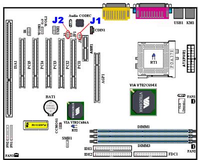
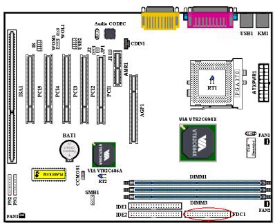
1-3. Layout Diagram
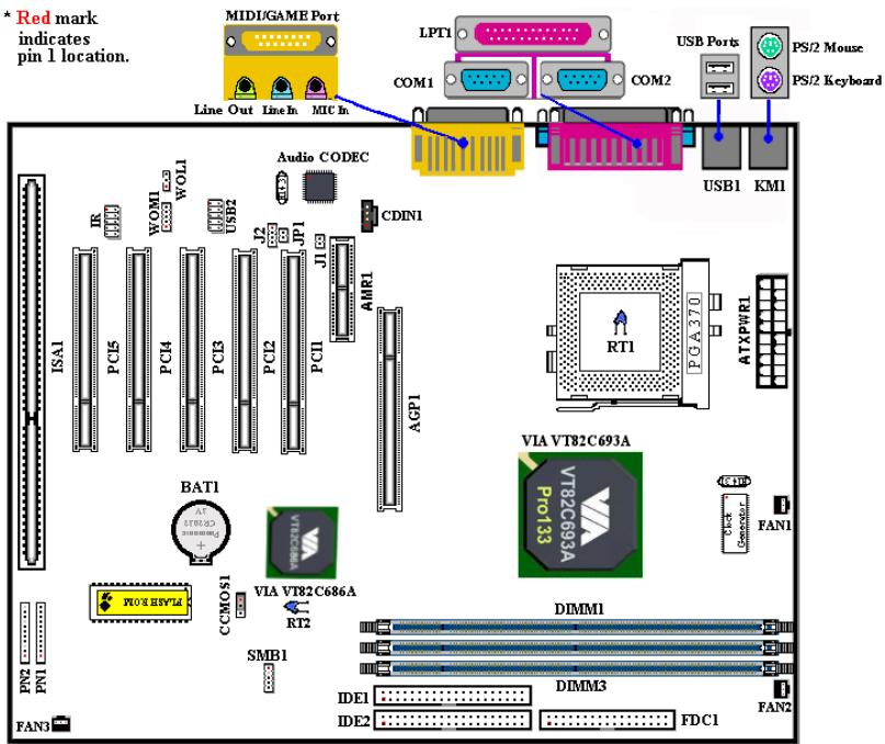
Figure 1-2. VL6 Motherboard component location
1-4. The System Block Diagram
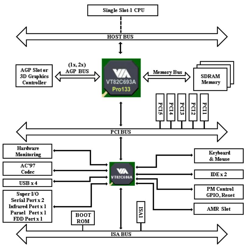
Figure 1-3. System diagram of the VIA Apollo Pro 133 chipset
Chapter 2. Installing the Motherboard
This VL6 motherboard not only provides all standard equipment for classic personal computers, but also provides great flexibility for meeting future upgrade demands. This chapter will introduce step by step all of the standard equipment and will also present, as completely as possible, future upgrade capabilities. This motherboard is able to support all Intel® Pentium® III (FC-PGA) processors and Intel® Celeron™ (PPGA & FC-PGA) processors now on the market. (For details, see specifications in Chapter 1.)
This chapter is organized according the following features:
2-1 Installing the Motherboard to the Chassis
2-2 Installation of the Intel Pentium III (FC-PGA) & Celeron™ (PPGA & FC-PGA) CPU
2-3 Installing System Memory
2-4 Connectors, Headers and Switches

Before Proceeding with the Installation

Before you install or unplug any connectors or add-on cards, please remember to turn the ATX power supply switch off (fully turn the +5V standby power off), or take the power cord off. Otherwise, you may cause the motherboard components or add-on cards to malfunction or be damaged.
User Friendly Instructions
Our objective is to enable the novice computer user to perform the installation by himself. We have attempted to write this document in a very clear, concise and descriptive manner to help overcome any obstacles you may face during installation. Please read our instructions carefully and follow them step-by-step.
2-1. Installing the Motherboard to the Chassis
Most computer chassis will have a base on which there will be many mounting holes that allows the motherboard to be securely attached and at the same time, prevents short circuits. There are two ways to attach the motherboard to the base of chassis:
with studs
or with spacers
Please refer to figure 2-1, which shows the studs and spacers. There may be several types, but all look like the figures below:
In principle, the best way to attach the motherboard is with studs. Only if you are unable to do this
should you attach the board with spacers. Take a careful look at the motherboard and you will see many mounting holes on it. Line these holes up with the mounting holes on the base. If the holes line up and there are screw holes this means you can attach the

STUD

SPACER
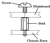
Figure 2-1. The outline of stub and spacer
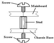

Figure 2-2. The way we fixed the motherboard
motherboard with studs. If the holes line up and there are only slots, this means you can only attach the motherboard with spacers. Take the tip of the spacers and insert them into the slots. After doing this to all the slots, you can slide the motherboard into position aligned with the slots. After the motherboard has been positioned, check to make sure everything is OK before putting the casing back on.
Figure 2-2 shows you the way to affix the motherboard using studs or spacers:
Note
If the motherboard has mounting holes, but they don't line up with the holes on the base and there are no slots to attach the spacers, don't worry, you can still attach the spacers to the mounting holes. Just cut the bottom portion of spacers (the spacer they may be a little hard to cut, so be careful with your hands). In this way you can still attach the motherboard to the base without worrying about short circuits. Sometimes you may need to use the plastic springs to isolate the screw from the motherboard PCB surface, because the circuit wire may be near by the hole. Be careful, don't let the screw contact any the printed circuit wire or parts on the PCB that are near the fixing hole, otherwise it may damage the board or cause board malfunctioning.
2-2. Installation of the Intel® Celeron™ (PPGA & FC-PGA) & Pentium® III (FC-PGA) processors
The Intel® Celeron™ (PPGA & FC-PGA) & Pentium® III (FC-PGA) package processor installation, is easy, like Socket 7 Pentium® processors before. Because it uses the "Socket 370" ZIF (Zero Insertion Force) socket, it lets you easily fix the processor on to its position firmly. Figure 2-3 shows you what the 370 socket looks like, and how to open the lever. Its pin count is more than socket 7. Therefore, a Pentium level processor cannot be inserted into socket 370.
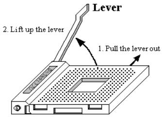
Figure2-3. Socket 370 and open its lever
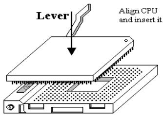
Figure 2-4. Install the CPU into socket 370
When you raise the lever, you have to loosen the socket lock. Please raise the lever to the end, and prepare to insert the processor. Next, you need to align the processor pin 1 to the socket pin 1. If you put it in the wrong direction, you will not be able to insert the processor easily, and processor pins will not fully go into the socket. If that is the case, please change the direction, until it easily and fully inserts into the 370 socket. See Figure 2-4.
When you finish the above, push the lever down to its original position, and you should feel the lever lock up the 370 socket. You have then finished the processor installation.
2-3. Installing System Memory
This motherboard provides three 168-pin DIMM sites for memory expansion. The DIMM sockets support 1Mx64 (8MB), 2Mx64 (16MB), 4Mx64 (32MB), 8Mx64 (64MB), 16Mx64 (128MB), and 32Mx64 (256MB) or double sided DIMM modules. Minimum memory size is 8MB and maximum memory size is 768MB SDRAM. There are three Memory module sockets on the system board. (Total six banks)
In order to create a memory array, certain rules must be followed. The following set of rules allows for optimum configurations.
- The memory array is 64 or 72 bits wide. (depending on with or without parity)
- Those modules can be populated in any order.
Supports single and double density DIMMS.
Table 2-1. Valid Memory Configurations
| Bank | Memory Module | Total Memory |
| Bank 0,1 (DIMM1) | 8MB, 16MB, 32MB, 64MB, 128MB, 256MB | 8MB ~ 256MB |
| Bank 2,3 (DIMM2) | 8MB, 16MB, 32MB, 64MB, 128MB, 256MB | 8MB ~ 256MB |
| Bank 4,5 (DIMM3) | 8MB, 16MB, 32MB, 64MB, 128MB, 256MB | 8MB ~ 256MB |
| Total System Memory | 8MB ~ 768MB | |
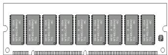
Figure 2-5 PC100/PC133 Module and Component Mark
Generally, installing SDRAM modules to your motherboard is an easy thing to do. You can refer to figure 2-5 to see what a 168-pin PC100 & PC133 SDRAM module looks like.
Unlike installing SIMMs, DIMMs may be "snapped" directly into the socket. Note: Certain DIMM sockets have minor physical differences.
If your module doesn't seem to fit, please do not force it into the socket as you may damage your memory module or DIMM socket.
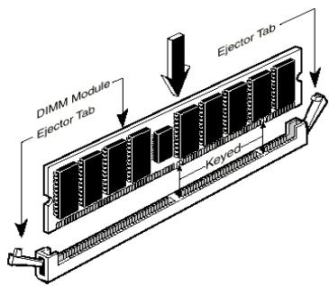
Figure 2-6. Memory module installation
The following procedure will show you how to install a DIMM module into a DIMM socket.
Step 1. Before you install the memory module, please place the computer power switch in the off position and disconnect the AC power cord from your computer.
Step 2. Remove the computer's chassis cover.
Step 3. Before touching any electronic components, make sure you first touch an unpainted, grounded metal object to discharge any static electricity stored on your clothing or body.
Step 4. Locate your computer's 168-pin memory expansion DIMM socket.
Step 5. Insert the DIMM module into the expansion socket as shown in the illustration. Note how the module is keyed to the socket. You can refer to figure 2-6 for the details. This insures the DIMM module will be plugged into the socket in one way only. Firmly press the DIMM module into the DIMM socket, making certain the module is completely seated in the DIMM socket.
Step 6. Once the DIMM module has been installed, the installation is complete and the computer's cover can be replaced. Or you can continue to install other devices and add-on cards that are mentioned in the following section.
Note
When you install a DIMM module fully into the DIMM socket, the eject tab should be locked into the DIMM module very firmly and fit into its indentation on the both sides.
You are hard to make different from its outside look between PC100 and PC133 SDRAM module, the only way you can identify them is to see the sticker on the RAM module. The sticker will show you the RAM module is which kind structure module.
2-4. Connectors, Headers and Switches
Inside the case of any computer several cables and plugs have to be connected. These cables and plugs are usually connected one-by-one to connectors located on the motherboard. You need to carefully pay attention to any connection orientation the cables may have and, if any, notice the position of the first pin of the connector. In the explanations that follow, we will describe the significance of the first pin.
We will show you all of the connectors, headers and switches here, and tell you how to connect them. Please pay attention and read the entire section for necessary information before attempting to finish all of the hardware installation inside the computer chassis.
Figure 2-7 shows you all of the connectors and headers that we'll discuss in the next section, you can use this diagram to visually locate each connector and header we describe.
All connectors, headers and switches mentioned here, will depend on your system configuration. Some features you may (or may not) have and need to connect or configure depending on the peripheral. If your system doesn't have such add-on cards or switches you can ignore some special feature connectors.
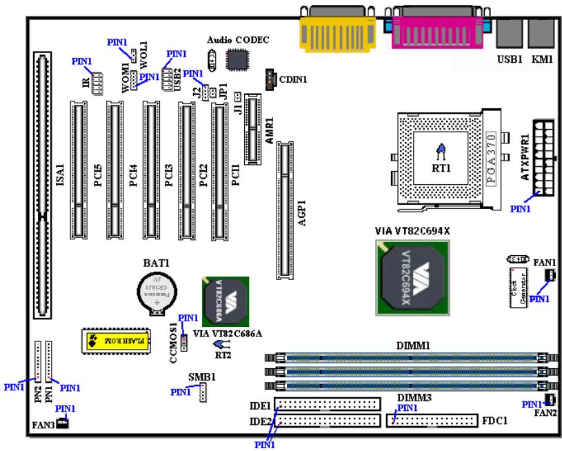
Figure 2-7. All Connectors and Headers for the VL6
First, Let's see the headers that VL6 uses, and what their functions are.
(1) ATXPWR1: ATX Power Input Connector
Caution
If the power supply connectors are not properly attached to the ATXPWR1 power supply, the power supply or add-on cards may be damaged.
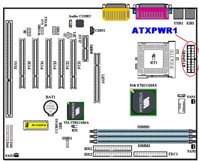
Attach the connector from the power supply to the ATXPWR1 connector here. Remember you have to push the connector from the ATX power supply firmly to the end with the ATXPWR1 connector, insuring that you have a good connection.
Note: Watch the pin position and the orientation
(2A)/(2B)/(2C): FAN1, FAN2 & FAN3 header
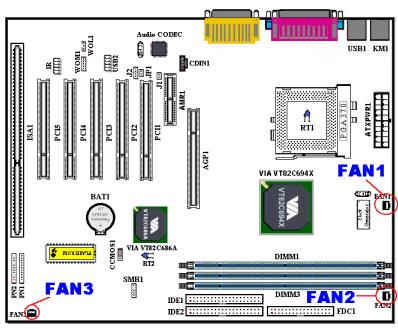
Attach the connector from the individual CPU fan to the header named FAN1, connector from the chassis fan to the header FAN3 and attach the connector from the power fan to FAN2 header.
You must attach the CPU fan to the processor, or your processor will work abnormally or may be damaged by overheating. Also, if you want the computer case's internal temperature to be kept steady and not too high, you had better connect the chassis fan to reach this goal.
Note: Watch the pin position and the orientation
(3) IR: IR Header (Infrared)
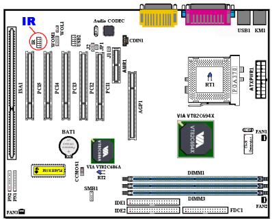
There is a specific orientation for pins 1 through 5, attach the connector from the IR KIT or IR device to the IR1 header (left row only). This motherboard supports standard IR transfer rates.
Note: Watch the pin position and the orientation
(4) WOM1: Wake On Modem Header
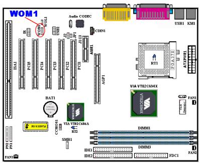
If you have an internal modem adapter that supports this feature, then you can connect the specific cable from the internal modem adapter to this header. This feature lets you wake up your computer via remote control through the modem.
Note: Watch the pin position and the orientation
(5) WOL1: Wake on LAN Header
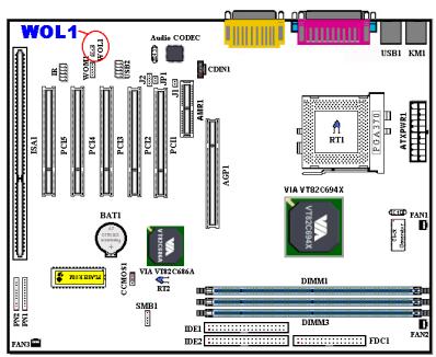
If you have a network adapter that supports this feature, then you can connect the specific cable from the network adapter to this header. This feature lets you wake up your computer via remote control through a local area network. You may need a specific utility to control the wake up event, like using the PCnet Magic Packet utility or other similar utilities.
Note: Watch the pin position and the orientation
(6) SMB1: System Management Bus Connector
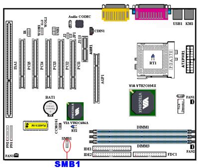
This connector is reserved for system management bus (SM bus). The SM bus is a specific implementation of an I^2C bus. I^2C is a multi-master bus, which means that multiple chips can be connected to the same bus and each one can act as a master by initiating a data transfer. If more than one master simultaneously tries to control the bus, an arbitration procedure decides which master gets priority.
Note: Watch the pin position and the orientation
(7A)/(7B): RT1 & RT2 Thermister:
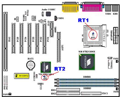
The RT1 thermistor used to detect the CPU temperature.
The RT2 is a thermistor used to detect the system environmental temperature. It may also be called a system temperature detector.
(8) USB2 Headers: Additional USB Plugs Header
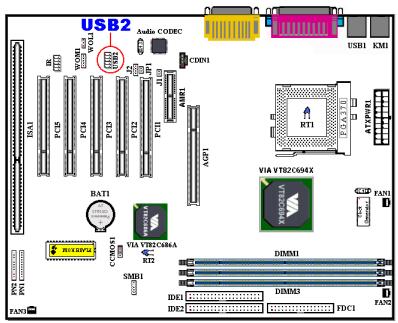
This header is for connecting the additional USB ports plugs. You can use the special USB port expend cable (option), it can provide you additional two USB plugs, you can fix these USB plugs on the back panel.
| Pin number | Name or significance of signal |
| 1 | NC |
| 2 | NC |
| 3 | VCC0 |
| 4 | VCC1 |
| 5 | Data - |
| 6 | Data1 - |
| 7 | Data + |
| 8 | Data1 + |
| 9 | Ground |
| 10 | Ground |
(9) CDIN1: Internal CD-ROM Drive Audio Cable Header
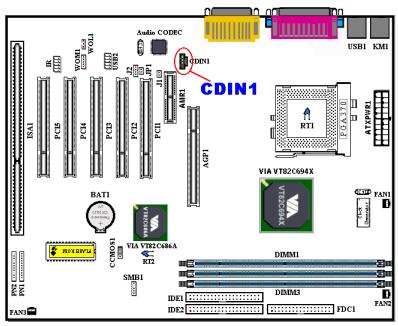
This header is for the internal CD-ROM drive audio cable connection use, and this header are used for specify type of CD audio cable connector. Please check your audio cable attached with the CD-ROM drive to see which type connector you have, then plug it to this header.
(10) CCMOS1: CMOS Discharge Jumper
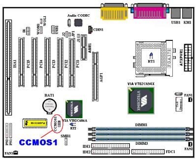
Jumper CCMOS1 discharge CMOS memory. When you install the motherboard, make sure this jumper is set for normal operation (pin 1 and 2 shorted). See figure 2-8.
Pin 1-2
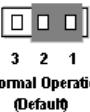
Pin 2-3

Figure 2-8. CCMOS1 jumper setting
Note
Before you clear the CMOS, you have to first turn the power off (including the +5V standby power). Otherwise, your system may work abnormally or malfunction.
(11) J1 & J2 Headers:
insertion on the AMR slot, then choose the choose the "AC 97 & MC 97" setting.
There are two headers to use for selecting the functions for the audio CODEC and/or the AMR card. Please refer to the table below for the proper settings.
| J1 | J2 | |
| AC 97 | Short | 1-2 Pin Short |
| MC 97 | Open | 3-4 Pin Short |
| AC 97 & MC 97 | Short | 1-2 Pin Short 3-4 Pin Short |
For example, if you want to use the onboard audio CODEC, choose the "AC97" settings. If you want to use the modem CODEC card
"MC 97" setting. If you want both to work,
(12) JP1 Header: AMR Function Selection
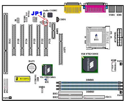
This header can select whether the AMR card insertion on the AMR slot is primary or secondary. When you don't want to use the onboard audio CODEC, you have to set JP1 at open. The default setting is short. Remember that only when using an MC 97 card should you select the JP1 as open. Otherwise, leave it selected as short.
| Items | AMR Card |
| JP1 short | Secondary |
| JP1 Open | Primary |
(13) PN1 and PN2 Headers
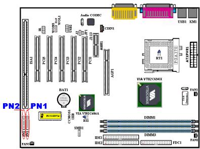
PN1 and PN2 are for switches and indicators for the chassis's front panel, there are several functions that come from these two headers. You have to watch the pin position and the orientation, or you may cause system malfunctions. Figure 2-9 shows you the PN1 and PN2 functions of the pins.


Figure 2-9. The definition of PN1 and PN2 pins
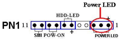
PN1 (Pin 1-2-3-4-5): Power LED Headers

and orientation.
There is a specific orientation for pins 1 through 3. Insert the three-threaded power LED cable to pins 1 3 . Check to make sure the correct pins go to the correct connectors on the motherboard. If you install them in the wrong direction, the power LED light will not illuminate correctly.
Note: Watch the power LED pin position
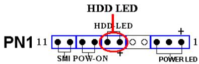
PN1 (Pin 6-7): HDD LED Header

Attach the cable from the case's front panel HDD LED to this header. If you install it in the wrong direction, the LED light will not illuminate correctly.
Note: Watch the HDD LED pin position and the orientation.
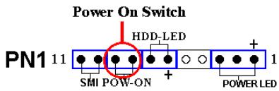
PN1 (Pin 8-9): Power on Switch Header

Attach the cable from the case's front panel power switch to this header.
PN1 (Pin 10-11): Hardware Suspend Switch (SMI Switch) Header
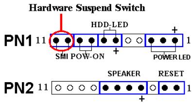
Attach the cable from the case's front panel suspend switch (if there is one) to this header. Use this switch to enable/disable the power management function by hardware.
Note: If ACPI function in the BIOS setup is enabled, this function will not work.
PN2 (Pin 1-2): Hardware Reset Switch Header
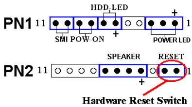
Attach the cable from the case's front panel Reset switch to this header. Press and hold the reset button for at least one second to reset the system.
PN2 (Pin 4-5-6-7): Speaker Header
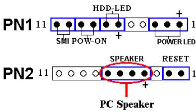
Attach the cable from the system speaker to this header.
For the PN1 and PN2 pin's count-name list, please refer to table 2-2.
Table 2-2. PN1 and PN2 pin count name list
| PIN Name | Significance of signal | PIN Name | Significance of signal | ||
| PN1 | PIN 1 | +5VDC | PN2 | PIN 1 | Ground |
| PIN 2 | No connection | PIN 2 | Reset input | ||
| PIN 3 | Ground | PIN 3 | No connection | ||
| PIN 4 | No connection | PIN 4 | +5VDC | ||
| PIN 5 | No connection | PIN 5 | Ground | ||
| PIN6 | LED power | PIN6 | Ground | ||
| PIN 7 | HDD active | PIN 7 | Speaker data | ||
| PIN 8 | Ground | PIN 8 | No connection | ||
| PIN 9 | Power On/Off signal | PIN 9 | No connection | ||
| PIN 10 | Ground | PIN 10 | No connection | ||
| PIN 11 | Suspend signal | PIN 11 | No connection | ||
Let's now see the I/O connectors that VL6 uses, and what their functions are.
(14) FDC1 Connector
FDC1
This 34-pin connector is called the "floppy disk drive connector". You can connect a 360K, 5.25", 1.2M, 5.25", 720K, 3.5", 1.44M, 3.5" or 2.88M, 3.5" floppy disk drive, you can even connect a 3 Mode floppy disk drive (it's a 3 1/2" drive used in Japanese computer systems).
A floppy disk drive ribbon cable has 34 wires and two connectors to provide the connection of two floppy disk drives. After connecting the single end to the FDC1, connect the two connectors on the other end to the floppy disk drives. In general, people
only install one floppy disk drive on their computer system.
Note
A red mark on a wire typically designates the location of pin 1. You need to align the wire pin 1 to the FDC1 connector pin 1, then insert the wire connector into the FDC1 connector.
(15) IDE1 and IDE2 Connectors
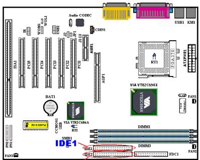
IDE2
An IDE hard disk drive ribbon cable has 40 wires and two connectors to provide a connection for two IDE hard disk drives. After connecting the single end to the IDE1 (or IDE2), connect the two connectors on the other end to the IDE hard disk drives (or CD-ROM drive, LS-120, etc.).
Before you install a hard disk, there are some things you need to be aware of:
"Primary" refers to the first connector on the motherboard, that is, the IDE1 connector on the motherboard.
"Secondary" refers to the second connector on the motherboard, that is, the IDE2 connector on the motherboard.
Two hard disks can be connected to each connector:
The first HDD is referred to as the "Master", the second HDD is referred to as the "Slave".
For performance issues, we strongly suggest you not to install CD-ROM drive on the same IDE channel with hard disk. Otherwise, the system performance on this channel may drop. (For dropping how much is depending on your CD-ROM drive performance.)
Note
- The Master or Slave status of the hard disk drive is set on the hard disk itself. Please refer to the hard disk drive user's manual.
- A red mark on a wire typically designates the location of pin 1. You need to align the wire pin 1 to the FDC1 connector pin 1, then insert the wire connector into the FDC1 connector.
The VL6 supports the Ultra ATA/66 (Also known as Ultra DMA/66) specification. It enhances existing Ultra ATA/33 technology by increasing both performance and data integrity. This new high-speed interface doubles the Ultra ATA/33 burst data transfer rate to 66.6 Mbytes/sec. The result is maximum disc performance using the current PCI local bus environment. Figure 2-10 shows you the difference between the Ultra ATA/33 and Ultra ATA/66 Conductor Cable.
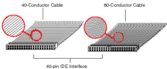
Figure 2-10. The difference between Ultra ATA/33 and Ultra ATA/66 Conductor Cables
Figure 2-11 shows you a photo of an Ultra ATA/66 Conductor Cable. An Ultra ATA/66-capable cable is a 40-pin, 80-conductor cable with a black connector on one end, a blue connector on the other end and a gray connector in the middle. In addition, line 34 on the cable should be notched or cut (this may be difficult to see).
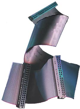
Figure 2-11. Photo of an Ultra ATA/66 Conductor
Ultra ATA/66 is backwards compatible with all Ultra ATA/33 systems, but it will be limited in its transfer mode to the Ultra ATA/33 (Ultra DMA Mode 2 - 33 Mbytes/sec) or PIO Mode 4 (16.6 Mbytes/sec). Ultra ATA/66 hard drives are 100 percent backward compatible with both Ultra ATA/33 and DMA and with existing ATA (IDE) hard drives, CD-ROM drives, and host systems. The Ultra ATA/66 protocol and commands are designed to be compatible with existing ATA (IDE) devices and systems. Although a new 40-pin, 80-conductor cable is required for Ultra ATA/66, the chip set pin connector remains the same at 40. Hard drives that support Ultra ATA/66 also support Ultra ATA/33 and legacy ATA (IDE) specifications.
There are four requirements for attaining Ultra ATA/66:
*The drive must support Ultra ATA/66.
*The motherboard and system BIOS (or an add-in controller) must support Ultra ATA/66.
The operating system must support Direct Memory Access (DMA); Microsoft Windows 98 and Windows 95B (OSR2) support DMA.
The cable must be an 80-pin conductor. The length should not exceed 18 inches. If all of the above requirements are met, you can enjoy the Ultra ATA/66 features of your computer system.
How to install the Ultra ATA/66 Cable Assembly:

Figure 2-12. How to connect an ATA/66 Cable to the Motherboard
The BLUE connector MUST be plugged into the motherboard or your system will not work.
Each connector on the Ultra ATA/66 cable assembly has a small polarization tab centrally located on the body of the plastic. This fits into the matching slot on the mating plugs on the motherboard and the drives, thus assuring positive mating (pin #1 to pin #1)
The red line on the cable should be aligned with pin #1. On the drives this will result in the red line facing the power connector. Attach the BLUE connector to
the appropriate 40 pin IDE plug on the motherboard.
- Attach the BLACK connector to the mating plug on the master hard drive. Attach the GREY connector to the mating plug on the slave drive (secondary hard drive, CD-ROM, or tape drive). Please refer figure 2-12.
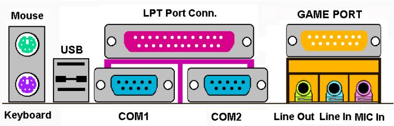
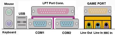
Figure 2-13. VL6 back panel connectors
Figure 2-13 shows the VL6 back panel connectors, these connectors are for connection to outside devices to the motherboard. We will describe which devices will attach to these connectors below.
KM1 Lower: PS/2 Keyboard Connector
Attach a PS/2 keyboard connector to this 6-pin Din-connector. If you use an AT keyboard, you can go to a computer store to purchase an AT to ATX converter adapter, then you can connect your AT keyboard to this connector. We suggest you use a PS/2 keyboard for best compatibility.
KM1 Upper: PS/2 Mouse Connector
Attach a PS/2 mouse to this 6-pin Din-connector.

USB Port Connectors
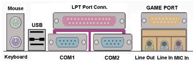
This motherboard provides two USB ports. Attach the USB connector from the individual device to these connectors.
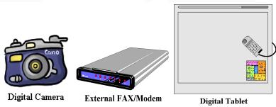
You can attach USB devices such as a, scanner, digital speakers, monitor, mouse,
keyboard, hub, digital camera, joystick etc. to one of each USB connector. You must make sure your operating system supports this feature and you may need to install an additional driver for individual devices. Please refer to your device user's manual for detailed information.
Serial Port COM1 & COM2 Port Connector
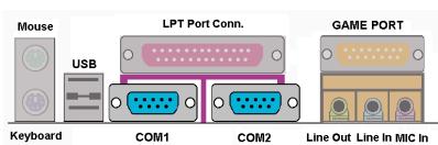
This motherboard provides two COM ports, you can connect an external modem, mouse or other devices that support this communication protocol to these connectors.
You can decide which external devices you want to connect to COM1 and COM2. Each COM port can only have one device connected at a time.
Parallel Port Connector
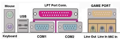
This parallel port is also called an "LPT" port, because it usually connects to the printer. You can connect other devices that support this communication protocol, like an EPP/ECP scanner, etc.

Line Out, Line In and Mic In Connector

Line Out connector: You can connect an external stereo speaker signal input plug to this connector, or you can connect the plug from here to the stereo audio equipment AUX signal input socket. Remember, the motherboard does not have a built in amplifier to drive the speaker. You must use a speaker that has a built in amplifier. Otherwise, you may not be able to hear any sound or only a small volume of sound from the speaker.

Line In Connector: You can connect the TV adapter audio output signal, or external audio sources, like a CD walkman, video camcorder, VHS recorder audio output signal plug to this connector. Your audio
software can control the input level for the line-in signal.

Mic In Connector: You can connect the plug from the microphone to this connector. Do not connect other audio (or signal) sources to this connector.
MIDI/GAME Port Connector
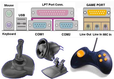
You can connect your joystick, game pad, or other simulation hardware device DIN 15-pin plugs to this connector. Please refer to the further connection notes of the device's user's manual for further detailed information.
Note
This chapter contains many color drawing diagram and photos, we strongly recommend you to read this chapter use the PDF file we gave you that store in the CD-Title. It will provide you the better look and clearly color identify.
Chapter 3. Introducing the BIOS
The BIOS is a program located on a Flash Memory chip on the motherboard. This program will not be lost when you turn the computer off. This program is also referred to as the boot program. It is the only channel the hardware circuit has to communicate with the operating system. Its main function is to manage the setup of the motherboard and interface card parameters, including simple parameters such as time, date, hard disk drive, as well as more complex parameters such as hardware synchronization, device operating mode, CPU SOFT MENU^TM II features and setup of CPU speed. The computer will operate normally, or will operate at its best, only if all of these parameters are correctly configured through the BIOS.

Don't change the parameters inside the BIOS unless you fully understand their meanings and consequences
The parameters inside the BIOS are used to setup the hardware synchronization or the device-operating mode. If the parameters are not correct, they will produce errors, the computer will crash, and sometimes you will even not be able to boot the computer after it has crashed. We recommend that you do not change the parameters inside the BIOS unless you are very familiar with them. If you are not able to boot your computer anymore, please refer to the section "Erase CMOS data" in Chapter 2.
When you start the computer, the BIOS program controls it. The BIOS first operates an auto-diagnostic test called POST (Power On Self Test) for all of the necessary hardware. It then configures the parameters of the hardware synchronization, and detects all of the hardware. Only when these tasks are completed does it give up control of the computer to the program to the next level, which is the operating system (OS). Since the BIOS is the only channel for hardware and software to communicate, it is the key factor for system stability, and in insuring that your system performs at its best. After the BIOS has achieved the auto-diagnostic and auto-detection operations, it will display the following message:
PRESS DEL TO ENTER SETUP
The message will be displayed for three to five seconds, if you press the key, you will access the BIOS Setup menu. At that moment, the BIOS will display the following screen:
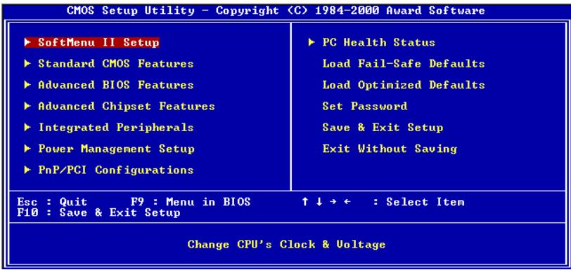
Figure 3-1. CMOS Setup Utility
In the BIOS Setup main menu of Figure 3-1, you can see several options. We will explain these options step by step in the following pages of this chapter, but let us first see a short description of the function keys you may use here:
- Press Esc to quit the BIOS Setup.
- Press (up, down, left, right) to choose, in the main menu, the option you want to confirm or to modify.
- Press F10 when you have completed the setup of BIOS parameters to save these parameters and to exit the BIOS Setup menu.
- Press Page Up/Page Down or +/- keys when you want to modify the BIOS parameters for the active option.
Computer Knowledge: CMOS Data
Maybe you have heard somebody saying that his or her CMOS DATA was lost. What is the CMOS? Is it important? The CMOS is the memory used to store the BIOS parameters that you have configured. This memory is passive. You can read its data, and you can also store data in it. But this memory has to be powered by a battery, in order to avoid any loss of its data when the computer is turned off. Since you may have to change the CMOS battery when it is out of power and if doing so, you will loose all CMOS data, therefore, we recommend that you write down all the parameters of your hardware, or to put a label with these parameters on your hard disk.
3-1. CPU Setup [SOFT MENU™ II]
The CPU can be setup through a programmable switch (CPU SOFT MENU™ II), that replaces the traditional manual hardware configuration. This feature allows the user to more easily complete the installation procedures. You can install the CPU without configuring any jumpers or switches. The CPU must be setup according to its specifications.
In the first option, you can press
![ABIT VL6 - 3-1. CPU Setup [SOFT MENU™ II] - 1](/content/2025/01/174597/images/a8dcbf32bf671f9803d0889bf3dd1ec5c1d72debea2ab0c5a4b9be6f37fd3320.jpg)
Figure 3-2. CPU SOFT MENU™ II
CPU Name Is:
Intel Celeron MMX
Intel Pentium III MMX
CPU Operating Speed:
This option sets the CPU speed. In this field, the CPU speed is indicated like this: CPU speed = External clock * Multiplier factor, select the CPU speed according to the type and the speed of your CPU. For Intel Pentium® III and Celeron™ MMX processors, you can choose the following settings:
300(66) >333(66) >366(66) >400(66) >400(100)
433 (66) 450 (100) 466 (66) 500(66) 500 (100)
533 (66) 533 (133) 550 (100) 566 (66) 600 (66)
600(100) >600(133) >650(100) >667(66) >667(133)
> 700 (66) > 700 (100) > 733 (133) > 750 (100) > 800 (100)
800(133) >850(100) >866(133) >900(100) >933(133)
1000 (133) User Define
User defined external clock and multiplier factor:
User Defined

Warning

The wrong settings of the multiplier and external clock in certain circumstances may cause CPU damage. Setting the working frequency higher than the PCI chipset or processor specs, may cause abnormal memory module functioning, system hangs, hard disk drive data lose, abnormal functioning of the VGA card, or abnormal functioning with other add-on cards. Using non-specification settings for your CPU is not the intention of this explanation. These should be used for engineering testing, not for normal applications.
If you use non-specification settings for normal operation, your system may not be stable, and may effect system reliability. Also, we do not guarantee the stability and compatibility for settings that are not within specification, and any damage of any elements on the motherboard or peripherals, is not our responsibility.
Ext. Clock (PCI):
66MHz(1/2)
100MHz(1/3)
133MHz (1/4)
150MHz(1/4)
140MHz(1/4)
105MHz(1/3)
>110MHz (1/3)
115MHz(1/3)
120MHz(1/3)
112MHz(1/3)
103MHz(1/3)
83MHz(1/2)
75MHz (1/2)
124MHz(1/3)
te
CPU bus speed above 66MHz / 100MHz / 133MHz supported but not guaranteed due to the PCI, processor and chipset specs.
= MultiplierFactor:
You can choose the following multiplier factors:
2
2.5
3
3.5
4
4.5
5
5.5
6
6.5
7
7.5
8.5
9
9.5
10
10.5
11
11.5
12
However, differences will exist because of the various brands and types available.
Note
According to Celeron™ PPGA MMX processor types, some Celeron™ PPGA MMX processors will have the multiplier factor locked and the signal disabled. In this situation, there is no way to choose a higher multiplier factor.
= Speed Error Hold:
The default setting is "Disabled". If you change the setting to "Enabled" when the CPU speed setting is wrong, the system will hold.
Normally, we do not recommend that you use the "User Define" option to setup CPU speed and multiplier factors. This option is for setup of future CPUs whose specifications are still unknown. The specifications of all present CPUs are included in the default settings. Unless you are very familiar with all CPU parameters, it is very easy to make mistakes when you define the external clock and the multiplier factor by yourself.
Solution in case of booting problem due to invalid clock setup:
Normally, if the CPU clock setup is wrong, you will not be able to boot. In this case, turn the system off then on again. The CPU will automatically use its standard parameters to boot. You can then enter the BIOS Setup again and set up the CPU clock. If you can't enter the BIOS setup, you must try turning the system on a few times (3~4 times) or press "INSERT" key when turning on and the system will automatically use its standard parameters to boot. You can then enter BIOS SETUP again and set up the new parameters.
When you change your CPU:
This motherboard has been designed in such a way that you can turn the system on after having inserted a CPU in the socket without having to configure any jumpers or DIP switches. But if you change your CPU, normally you just have to turn off the power supply, change the CPU and then, set up the CPU parameters through SOFT MENU™ II. However, if the new CPU is slower than the old one (and is same brand and type), we offer you two methods to successfully complete the CPU change operation.
Method 1: Setup up the CPU for the lowest speed for its brand. Turn the power supply off and change the CPU. Then turn the system on again, and set up the CPU parameters through SOFT MENU™ II.
Method 2: Since you have to open the computer case when you change the CPU, it could be a good idea to use the CCMOS jumper to erase the parameters of the original CPU and to enter BIOS Setup to set up CPU parameters again.
Attention
After setting up the parameters and leaving the BIOS SETUP, and having verified that the system can be booted, do not press the Reset button or turn off the power supply. Otherwise the BIOS will not read correctly, the parameters will fail and you must enter SOFT MENU™ II again to set up the parameters all over again.
CPU Power Supply:
This option allows you to switch between CPU default and user-defined voltages.
CPU Default: The system will detect the CPU type and select the proper voltage automatically. When it is enabled, the option "Core Voltage" will show the current voltage setting that is defined by the CPU and this will not be changeable. We recommend using this CPU default setting and not changing it unless the current CPU type and voltage setting can not be detected or is not correct.
User Define: This option lets the user select the voltage manually. You can change values of the "Core Voltage" option lists by using the Page Up and Page Down keys.
Spread Spectrum:
Two options are available: Disabled Enabled. The default setting is Disabled. For EMC (Electro-Magnetic Compatibility Test) testing you may need to adjust these options for optimal results, we do not recommend you change the default, except for special reasons. Some values you select may cause system instability under some situations, please be careful.
CPU Hardwired IOQ:
Two options are available: 1 Level 4 Level. The default setting is 4 Level. This option will effect the pipeline depth between the processor and chipset Choose level 4 to get faster performance, and level 1 to get better stability.
3-2. Standard CMOS Features Setup Menu
This contains the basic configuration parameters of the BIOS. These parameters include date, hour, VGA card, FDD and HDD settings.
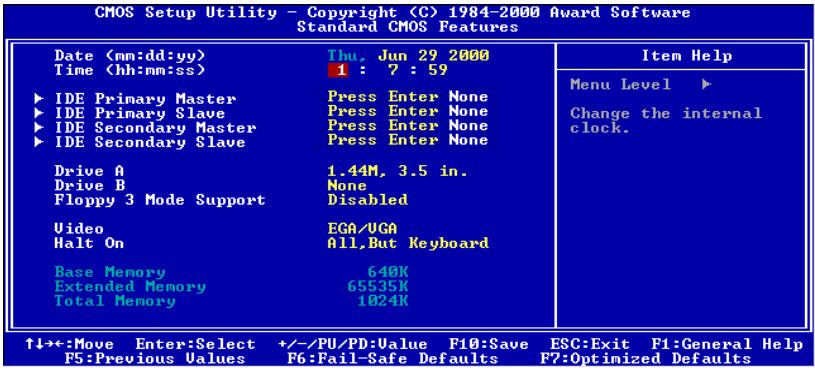
Figure 3-3A. Standard CMOS Setup Screen Shot
Date (mm:dd:yy):
You can set the date in this item: month (mm), date (dd) and year (yy).
Time (hh:mm:ss):
You can set the time in this item: hour (hh), minute (mm) and second (ss).
IDE Primary Master / Slave and IDE Secondary Master / Slave:
These items have a sub-menu to let you choose further options. You can refer to figure 3-3B to check what options are available.
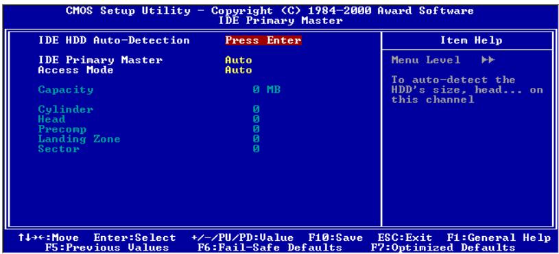
Figure 3-3B. IDE Primary Master Setup Screen Shot
IDE HDD Auto-Detection:
Press the Enter key for the BIOS to auto detect all detailed parameters of the hard disk drivers (HDD). If auto detection is successful, the correct values will be shown in the remaining items of this menu.
Note
A new IDE HDD must be first formatted, otherwise it can not read/write. The basic step in using a HDD is to make a HDD low-level format, then run FDISK, and then FORMAT the drive. Most current HDDs have already been subjected to low-level format at the factory, so you can probably skip this operation. Remember though, the primary IDE HDD must have its partition set to active within the FDISK procedure.
- If you are using an old HDD that is already formatted, auto detection can not detect the correct parameters. You may need to do a low-level format or set the parameters manually, and then check if the HDD is working.
IDE Primary Master:
Three settings are available: Auto, Manual and None. If you choose Auto, the BIOS will automatically check what kind hard disk you are using. If you want to set the HDD parameters yourself, make sure you fully understand the meaning of the parameters, and be sure to refer to the manual provided by the HDD manufacture to get the settings right.
Access Mode:
Since old operating systems were only able to support HDDs with capacities no bigger than 528MB, any hard disk with more than 528MB was unusable. AWARD BIOS features a solution to this problem: you can, according to your operating system, choose four operating modes: NORMAL LBA LARGE Auto.
The HDD auto detection option in the sub-menu will automatically detect the parameters of your hard disk and the mode supported.
Auto:
Just let the BIOS detect your HDD access mode and make the decisions.
Normal mode:
Standard normal mode supports hard disks of up to 528MB or less. This mode directly uses positions indicated by Cylinders (CYLS), Heads, and Sectors to access data.
LBA (Logical Block Addressing) mode:
The earlier LBA mode can support HDD capacities of up to 8.4GB, and this mode uses a different method to calculate the position of disk data to be accessed. It translates Cylinders (CYLS), Heads and Sectors into a logical address where data is located. The Cylinders, Heads, and Sectors displayed in this menu do not reflect the actual structure of the hard disk, they are just reference values used to calculate actual positions. Currently, all high capacity hard disks support this mode, that's why we recommend you use this mode. Currently, the BIOS can support the INT 13h extension function,
enabling the LBA mode to support hard disk drive capacities exceeding 8.4GB.
Large Mode:
When the number of cylinders (CYLs) of the hard disk exceeds 1024 and DOS is not able to support it, or if your operating system does not support LBA mode, you should select this mode.
Capacity:
This item auto displays your HDD size. Note that this size is usually slightly greater than the size given by a disk checking program of a formatted disk.
Note
All the items below are available when you set the item Primary IDE Master to Manual.
Cylinder:
When disks are placed directly above one another along the shaft, the circular vertical "slice" consisting of all the tracks located in a particular position is called a cylinder. You can set the number of cylinders for a HDD. The minimum number you can enter is 0, the maximum number you can enter is 65536.
Head:
This is the tiny electromagnetic coil and metal pole used to create and read back the magnetic patterns on the disk (also called the read/write head). You can configure the number of read/write heads. The minimum number you can enter is 0, the maximum number you can enter is 255.
Precomp:
The minimum number you can enter is 0, the maximum number you can enter is 65536.
Warning
Setting a value of 65536 means no hard disk exists.
Landing Zone:
This is a non-data area on the disk's inner cylinder where the heads can rest when the power is turned off. The minimum number you can enter is 0, the maximum number you can enter is 65536.
Sector:
The minimum segment of track length that can be assigned to stored data. Sectors usually are grouped into blocks or logical blocks that function as the smallest units of data permit. You can configure this item to sectors per track. The minimum number you can enter is 0, the maximum number you can enter is 255.
Driver A & Driver B:
If you have installed the floppy disk drive here, then you can select the type of floppy drive
it can support. Six options are available: None 360K, 5.25 in. 1.2M, 5.25 in. 720K, 3.5 in. 1.44M, 3.5 in. 2.88M, 3.5 in.
Floppy 3 Mode Support:
Four options are available: Disabled Driver A Driver B Both. The default setting is Disabled. 3 Mode floppy disk drives (FDD) are 31/2 ” drives used in Japanese computer systems. If you need to access data stored in this kind of floppy, you must select this mode, and of course you must have a 3 Mode floppy drive.
Video:
You can select the VGA modes for your video adapter, four options are available: EGA/VGA CGA 40 CGA 80 MONO. The default setting is EGA/VGA.
Halt On:
You can select which type of error will cause the system to halt. Five options are available: All Errors No Errors All, But Keyboard All, But Diskette All, But Disk/Key.
You can see your system memory list in the lower right box, it shows the Base Memory, Extended Memory and total Memory size configurations in your system. It is detected by the system during boot-up procedure.
3-3. Advanced BIOS Features Setup Menu
In each item, you can press
Attention
Advanced BIOS Features Setup Menu has already been set for maximum operation. If you do not really understand each of the options in this menu, we recommend you use the default values.
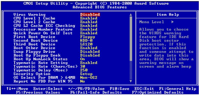
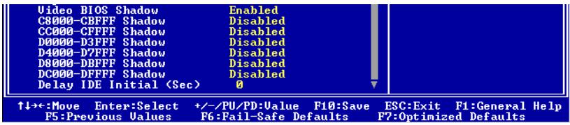
Figure 3-4A. Advanced BIOS Features Setup Upper Screen
Figure 3-4B. Advanced BIOS Features Setup Lower Screen
Virus Warning:
This item can be set to Enabled or Disabled, the default setting being Disabled.
When this feature is enabled, if there is any attempt from a software or an application to access the boot sector or the partition table, the BIOS will warn you that a boot virus is attempting to access the hard disk.
CPU Level 1 Cache:
This item is used to enable or to disable the CPU level 1 cache. When the cache is set to Disabled it is much slower, so the default setting for this item is Enabled since it will speed up memory access. Some old and very poorly written programs will make the computer malfunction or crash if the system speed is too high. In this case, you should disable this feature. The default setting is Enabled.
CPU Level 2 Cache:
This item is used to enable or to disable the CPU level 2 cache. When the external cache is enable, it will speed up memory access, and the system works faster. The default setting is Enabled.
CPU L2 Cache ECC Checking:
This item is used to enable or to disable the CPU level 2 cache ECC checking function. The default setting is Enabled.
Processor Number Feature
This feature can let the program read the data inside your processor. This feature only works with Intel® Pentium® III processors. When you install a Pentium® III processor on your motherboard and boot your system, this item will appear in the BIOS.
Two items will be available: Enabled and Disabled. When you choose Enabled, the specific program can read your processor's serial number. When you choose Disabled it will not allow the program to read your processor's serial number. The default setting is Enabled.
Quick Power On Self Test:
After the computer has been powered on, the BIOS of the motherboard will run a series of tests in order to check the system and its peripherals. If the Quick Power on Self-Test feature is enable, the BIOS will simplify the test procedures in order to speed up the boot process. The default setting is Enabled.
First Boot Device:
When the computer boots up, the BIOS attempts to load the operating system from the devices in the sequence selected in these items: floppy disk drive A, LS/ZIP devices, hard drive C, SCSI hard disk drive or CD-ROM. There are ten options for the boot sequence that you can choose (The default setting is Floppy.):
Floppy LS120 HDD-0 SCSI CDROM HDD-1 HDD-2 HDD-3 ZIP100 LAN Disabled.
Second Boot Device:
Description is the same as the First Boot Device, the default setting is HDD-0.
Third Boot Device:
Description is same as the First Boot Device, the default setting is LS/ZIP
Boot Other Device:
Two options are available: Enabled or Disabled. The default setting is Enabled. This setting allows the BIOS to try three kinds of boot devices that set from the above three items.
Swap Floppy Drive:
This item can be set as Enabled or Disabled. The default setting is Disabled. When this feature is enabled, you don't need to open the computer case to swap the position of floppy disk drive connectors. Drive A can be set as drive B and drive B can be set as drive A.
Boot Up Floppy Seek:
When the computer boots up, the BIOS detects if the system has a FDD or not. When this item is enable, if the BIOS detects no floppy drive, it will display a floppy disk drive error message. If this item is disabled, the BIOS will skip this test. The default setting is Disabled.
Boot Up NumLock Status:
On:At boot up, the Numeric Keypad is in numeric mode. (Default Settings)
Off: At boot up, the Numeric Keypad is in cursor control mode.
Typematic Rate Setting:
This item allows you to adjust the keystroke repeat rate. When set to Enabled, you can set the two keyboard typematic controls that follow (Typematic Rate and Typematic Rate Delay). If this item is set to Disabled, the BIOS will use the default setting. The default setting is Enabled.
Typematic Rate (Chars/Sec):
When you press a key continuously, the keyboard will repeat the keystroke according to the rate you have set (Unit: characters/second). Eight options are available: 6 8 10 12 15 20 24 30 Back to 6. The default setting is 30.
Typematic Delay (Msec):
When you press a key continuously, if you exceed the delay you have set here, the keyboard will automatically repeat the keystroke according to a certain rate (Unit: milliseconds). Four options are available: 250 500 750 1000 Back to 250. The default setting is 250.
Security Option:
This option can be set to System or Setup. The default setting is Setup. After you have created a password through PASSWORD SETTING, this option will deny access to your system (System) or modification of computer setup (BIOS Setup) by unauthorized users.
SYSTEM: When you choose System, a password is required each time the computer boots up. If the correct password is not given, the system will not start.
SETUP: When you choose Setup, a password is required only when accessing the BIOS Setup. If you have not set a password in the PASSWORD SETTING option, this option is not available.
To disable security, select Set Password at main menu and then you will be asked to enter password. Do not type anything and just press the Enter key and it will disable security. Once security is disabled, the system will boot and you can enter the BIOS setup menu freely
Notice
Don't forget your password. If you forget the password, you will have to open the computer case and clear all information in the CMOS before you can start up the system. But by doing this, you will have to reset all previously set options.
OS Select For DRAM >64MB
When the system memory is bigger than 64MB, the communication method between the BIOS and the operating system will differ from one operating system to another. If you use OS/2, select OS2; if you are using another operating system, select Non-OS2. The default setting is Non-OS2.
Report No FDD For WIN 95:
When using Windows® 95 without a floppy drive, please set this item to Yes. Otherwise, set it to No. The default setting is No.
Video BIOS Shadow:
This option is used to define whether the BIOS on the video card uses the shadow feature or not. You should set this option to Enabled, otherwise the display performance of the system will greatly decrease.
Shadowing address ranges:
This option allows you to decide if the ROM BIOS area of an interface card at a specific address uses the shadow feature or not. If you have no interface card using this memory block, don't enable this option.
You have six address ranges you can select:
C8000-CBFFF Shadow, CC000-CFFFF Shadow, D0000-D3FFF Shadow, D4000-D7FFF Shadow, D8000-DBFFF Shadow, DC000-DFFFF Shadow.
Computer Knowledge: SHADOW
What is the SHADOW? The BIOS of standard video or interface cards is stored in ROM, and it is often very slow. With the Shadow feature, the CPU reads the BIOS on the VGA card and copies it into RAM. When the CPU runs this BIOS, the operation is speeded up.
Delay IDE Initial (Sec):
This item is used to support some old models or special types of hard disks or CD-ROMs. They may need a longer amount of time to initialize and prepare for activation. Since the BIOS may not detect those kinds of devices during system booting. You can adjust the value to fit such devices. Larger values will give more delay time to the device. The minimum number you can enter is 0, the maximum number you can enter is 15. The default setting is 0. For best system performance, we strongly suggest you to set it to 0.
3-4. Advanced Chipset Features Setup Menu
The Chipset Features Setup Menu is used to modify the contents of the buffers in the chipset on the motherboard. Since the parameters of the buffers are closely related to hardware, if the setup is not correct or is false, the motherboard will become unstable or you will not be able to boot up. If you don't know the hardware very well, use default values (i.e. use the LOAD SETUP DEFAULTS option).
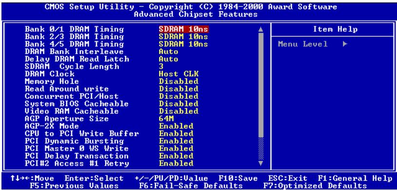
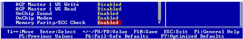
Figure 3-5A. Advanced Chipset Features Setup Upper Screen
Figure 3-5B. Advanced Chipset Features Setup Lower Screen
You can use the arrow keys to move between the items. Use PgUP , PgDn , + or - key to change the values. When you have finished setting up the chipset, press ESC to go back to the main menu.
Note
The parameters in this screen are for system designers, service personnel, and technically competent users only. Do not reset these values unless you understand the consequences of your changes.
Bank 0/1, 2/3, 4/5 DRAM Timing:
The DRAM timing of Bank 0/1, 2/3, 4/5 in this field is set by the motherboard manufacturer, depending on whether memory module preset. For end users, we do not suggest that you to change the setting. Except when you actually know what kind memory module you use.
The Choice: SDRAM 10ns SDRAM 8ns Normal Medium Fast Turbo Back to SDRAM 10ns. The default setting is SDRAM 10ns.
DRAM Bank Interleave:
Four options are available: Auto Disabled 2-Way 4-Way. The default setting is Auto. Depending on your SDRAM module structure, the 4-Way setting can make the performance best. If you choose the wrong setting, the computer system will not run in a stable manner. For detailed information on your SDRAM module, please ask your SDRAM module manufacturer.
Delay DRAM Read Latch:
Five options are available: Auto No Delay 0.5ns 1.0ns 1.5ns. The default setting is Auto. This option can increase the DRAM signal strength to give you better compatibility for DRAM modules.
SDRAM Cycle Length:
Two options are available: 2 or 3. This option sets the CAS latency timing of the DRAM system memory access cycle when SDRAM system memory is installed on the motherboard. The default setting is 3.
DRAM Clock:
Two options are available: Host CLK or 66 MHz. The default setting is Host CLK. This option is used to set the working speed of SDRAM same as CPU working frequency, or keep it at 66 MHz.
Memory Hole:
Two options are available: Disabled or 15M - 16M. The default setting is Disabled. This option is used to free up the memory block 15M-16M. Some special peripherals need to use a memory block located between 15M and 16M, and this memory block has a size of 1M. We recommend that you disable this option.
Read Around Write
Two options are available: Disabled or Enabled. The default setting is Disabled. This item is designed for DRAM optimization feature. If a memory read is addressed to a location whose latest write is being held in a buffer before being written to memory, the read is satisfied through the buffer contents, and the read is not sent to the DRAM
Concurrent PCI/Host
Two options are available: Disabled or Enabled. The default setting is Disabled. When disable, CPU bus will be occupied during the entire PCI operation period.
System BIOS Cacheable:
Two options are available: Disabled or Enabled. The default setting is Disabled. When you select Enabled, you get faster system BIOS executing speed via the L2 cache.
Video RAM Cacheable:
Two options are available: Disabled or Enabled. The default setting is Disabled. When you select Enabled, you get faster video RAM executing speed via the L2 cache. You must check your VGA adapter manual to find out if any compatibility problems will occur.
AGP Aperture Size:
Six options are available: 16M 32M 64M 128M 256M Back to 16M . The default setting is 64M . This option specifies the amount of system memory that can be used by the AGP device. The aperture is a portion of the PCI memory address range dedicated for graphics memory address space. Host cycles that hit the aperture range are forwarded to the AGP without any translation. See www.agpforum.org for AGP information.
AGP-2X Mode:
Two options are available: Disabled or Enabled. The default setting is Enabled. If you use the older AGP adapter that does not support AGP 2X mode, you need to set this item to Disabled.
CPU to PCI Write Buffer:
Two options are available: Disabled or Enabled. The default setting is Enabled. When enabled, up to four words of data can be written to the PCI bus without interrupting the CPU. When disabled, a write buffer is not used and the CPU read cycle will not be completed until the PCI bus signals that it is ready to receive the data. Because the CPU speed running faster than PCI bus, the CPU must wait as the PCI bus receives data before starting each write cycle.
PCI Dynamic Bursting:
Two options are available: Disabled or Enabled. The default setting is Enabled. When Enabled, every write transaction goes to the write buffer. Burstable transactions then burst on the PCI bus and nonburstable transactions don't. Which means, when you set to disabled, if the write transaction is a burst transaction, the information go to the write buffer and burst transfers are perform on the PCI bus later. If the transaction is not a burst transaction, PCI write will occur immediately. (it will active after a write buffer flush)
PCI Master 0 WS Write:
Two options are available: Disabled or Enabled. The default setting is Enabled. When Enabled, writes to the PCI bus are executed with zero wait states (immediately), when PCI bus is ready to receive data. If disabled, the system will wait one state before data is written to the PCI bus.
PCI Delay Transaction:
Two options are available: Disabled or Enabled. The default setting is Enabled. The chipset has an embedded 32-bit posted write buffer to support delay transactions cycles. Select Enabled to support compliance with PCI specification version 2.1.
PCI#2 Access #1 Retry:
Two options are available: Disabled or Enabled. The default setting is Enabled. This item allows you enable/disable the PCI #2 Access #1 Retry. When you set the PCI#2 Access#1 to Enabled, the AGP bus will attempt to access the PCI bus at a limited time period before being disconnected. When you set it to Disabled, the AGP bus will try to access the PCI bus until it successfully accesses the PCI bus.
AGP Master 1 WS Write:
Two options are available: Disabled or Enabled. The default setting is Disabled. This implements a single delay when writing to the AGP Bus. When you set it to Disabled, two-wait states are used by the system, allowing for greater stability.
AGP Master 1 WS Read:
Two options are available: Disabled or Enabled. The default setting is Disabled. This implements a single delay when reading to the AGP Bus. By default, two-wait states are used by the system, allowing for greater stability.
OnChip Sound:
Two options are available: Disabled or Enabled. The default setting is Enabled. Because this motherboard had built-in the Audio CODEC, so we set this item to Auto. If you want to use the other sound card with this motherboard, you have to disable this item.
OnChip Modem:
Two options are available: Disabled or Enabled. The default setting is Enabled. As this motherboard can use the modem riser card, you need to set it to "Enabled" in order to auto detect the device. If you want to use the other internal modem card with this motherboard, you have to disable this item.
Memory Parity/ECC Check:
Two options are available: Disabled or Enabled. The default setting is Disabled. This item can allow BIOS to check memory is parity/ECC module or not.
3-5. Integrated Peripherals
In this menu, you can change the onboard I/O device, I/O port address and other hardware settings.
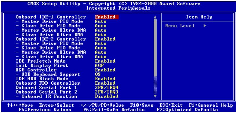
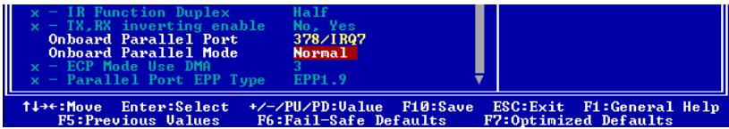
Figure 3-6A. Integrated Peripherals Menu Upper Screen
Figure 3-6B. Integrated Peripherals Menu Lower Screen
Onboard IDE-1 Controller:
The onboard IDE 1 controller can be set as Enabled or Disabled.
- Master Drive PIO Mode:
Auto: The BIOS can auto-detect the transfer mode of the IDE devices in order to set its data transfer rate. (Default)
You can select the PIO mode from 0 to 4 of the IDE devices in order to set its data transfer rate.
- Slave Drive PIO Mode:
Auto: The BIOS can auto-detect the transfer mode of the IDE devices in order to set its data transfer rate. (Default)
You can select the PIO mode from 0 to 4 of the IDE devices in order to set its data transfer rate.
Master Drive Ultra DMA:
Ultra DMA is a DMA data transfer protocol that utilizes ATA commands and the ATA bus to allow DMA commands to transfer data at a maximum burst rate of 66 MB/sec.
Auto: When you select Auto, the system automatically determines the optimal data transfer rate for each IDE device. (Default)
Disabled: If you encounter the problem of using Ultra DMA devices, you can try to Disable this item.
Slave Drive Ultra DMA:
Auto: When you select Auto, the system automatically determines the optimal data transfer rate for each IDE device. (Default)
Disabled: If you encounter the problem of using Ultra DMA devices, you can try to Disable this item.
Onboard IDE-2 Controller:
The onboard IDE-2 controller can be set at Enabled or Disabled.
- Master Drive PIO Mode:
Auto: The BIOS can auto-detect the transfer mode of the IDE devices in order to set its data transfer rate. (Default)
You can select the PIO mode from 0 to 4 of the IDE devices in order to set its data transfer rate.
- Slave Drive PIO Mode:
Auto: The BIOS can auto-detect the transfer mode of the IDE devices in order to set its data transfer rate. (Default)
You can select the PIO mode from 0 to 4 of the IDE devices in order to set its data transfer rate.
- Master Drive Ultra DMA: Ultra DMA is a DMA data transfer protocol that utilizes ATA commands and the ATA bus to allow DMA commands to transfer data at a maximum burst rate of 66 MB/sec.
Auto: When you select Auto, the system automatically determines the optimal data transfer rate for each IDE device. (Default)
Disabled: If you encounter a problem using Ultra DMA devices, you can try to Disable this item.
- Slave Drive Ultra DMA:
Auto: When you select Auto, the system automatically determines the optimal data transfer rate for each IDE device. (Default)
Disabled: If you encounter the problem of using Ultra DMA devices, you can try to Disable this item.
PIO MODE 0~4 reflects the IDE device data transfer rate. The higher the MODE value is, the better is the IDE device data transfer rate. But it does not mean that you can select the highest MODE value just as you like, you first have to be sure that your IDE device supports this MODE, otherwise the hard disk will not be able to operate normally.
IDE Prefetch Mode:
Two options are available: Disabled or Enabled. The default setting is Enabled. The onboard
IDE drive interfaces supports IDE prefetching, for faster drive accesses. If you install a primary and/or secondary add-in IDE interface, set this field to Disabled if the interface does not support prefetching.
Init Display First:
Two options are available: PCI Slot or AGP. The default setting is AGP . When you install more than one display cards, you can choose either a PCI display card (PCI Slot) or an AGP display card (AGP) to activate the display boot-up screen. If you only installed one display card, the BIOS will detect which slot (AGP or PCI) you installed it, in then everything will be take care of by the BIOS.
USB Controller:
Two options are available: Disabled or Enabled. The default setting is Enabled. This should be enabled if your system has a USB installed on the system board and you wish to use it. Even when so equipped, if you add a higher performance controller, you will need to disable this feature. If you choose disable this item, the "USB Keyboard Support" item will disappear in Chipset Features Setup menu.
- USB Keyboard Support: Two options are available: BIOS and OS. The default setting is OS. If your operating system supports a USB keyboard, please set it to OS. Only in some situations, such as in a pure DOS environment that does not support a USB keyboard, should you set it to BIOS.
IDE HDD Block Mode:
This item can be set as Enabled or Disabled.
Most of new hard disk drives (IDE drives) support multi-sector transfers. This feature speeds up hard disk drive access performance and reduces the time necessary to access data. When this item is enabled, the BIOS will automatically detect if your hard disk drive supports this feature or not, and will choose the right settings for you. (The default is Enabled)
Onboard FDD Controller:
Two options are available: Disabled or Enabled. The default setting is Enabled. This is set to Enabled or Disabled the Onboard FDD Controller. If you add a higher performance controller, you will need to disable this feature.
Onboard Serial Port 1:
This item allows you to determine access onboard serial port 1 controller with which I/O address. Six options are available: Auto Disabled 3F8/IRQ4 2F8/IRQ3 3E8/IRQ4 2E8/IRQ3 Back to Auto. The default setting is 3F8/IRQ4.
Onboard Serial Port 2:
This item allows you to determine access onboard serial port 2 controller with which I/O address. Six options are available: Auto Disabled 3F8/IRQ4 2F8/IRQ3 3E8/IRQ4 2E8/IRQ3 Back to Auto. The default setting is 2F8/IRQ3.
If you choose "Disabled", then item "Onboard IR Function" will disappear.
Onboard IR Function:
Three options are available: Disabled HPSIR ASKIR (Amplitude Shift Keyed IR). The default setting is Disabled.
When you select the item HPSIR or ASKIR, then the following two items will appear.
- IR Function Duplex: Two options are available: Half or Full. The default setting is Half. Select the value required by the IR device connected to the IR port. Full-duplex mode permits simultaneous two-direction transmission. Half-duplex mode permits transmission in one direction only at a time.
- TX, RX inverting enable: Four options are available: No, Yes Yes, No Yes, Yes No, No. This item allows you to determine the active of RxD, TxD.
Note
The setting for item "TX, RX inverting", also called "RxD, TxD Active", allows you to determine the activity of RxD, TxD. We set it fixed to "No, Yes". If your motherboard BIOS uses 'Hi' and 'Lo' to represent this item, you should set it to the same setting as the VL6. This means that you should set it to "Hi, Lo" in order to match the transfer and receiving speed. If you fail to do so, you will not get an IR connection between the VL6 and the other computer.
Onboard Parallel Port:
Four options are available: 378/IRQ7 278/IRQ5 Disabled 3BC/IRQ7. The default setting is 378/IRQ7. Select a logical LPT port name and matching address for the physical parallel (printer) port.
Onboard Parallel Mode:
Four options are available: Normal EPP ECP ECP/EPP. Default is Normal mode. Select an operating mode for the onboard parallel (printer) port. Normal (SPP, Standard Parallel Port), EPP (Extended Parallel Port), ECP (Extended Capabilities Port) or ECP plus EPP.
Select Normal unless you are certain your hardware and software both support EPP or ECP mode. According to your select the following items will separate show up.
- ECP Mode Use DMA: When the mode selected for the onboard parallel port is ECP or ECP/EPP, the DMA channel selected can be Channel 1 or Channel 3.
- Parallel Port EPP Type: Two options are available: EPP1.7 EPP1.9. The default setting is EPP 1.9. When the mode selected for the parallel port mode is EPP, the two EPP version options are available.
3-6. Power Management Setup Menu
The difference between Green PCs and traditional computers is that Green PCs have a power management feature. With this feature, when the computer is powered on but inactive, the power consumption is reduced in order to save energy. When the computer operates normally, it is in Normal mode. In this mode, the Power Management Program will control the access to video, parallel ports, serial ports and drives, and the operating status of the keyboard, mouse and other device. These are referred to as Power Management Events. In cases where none of these events occur, the system enters the power saving mode. When one of the controlled events occurs, the system immediately returns to normal mode and operates at its maximum speed. Power saving modes can be divided into three modes according to their power consumption: Doze Mode, Standby Mode, and Suspend Mode. The four modes proceed in the following sequence:
Normal Mode Doze Mode Standby Mode Suspend Mode

The system consumption is reduced according the following sequence:
Normal > Doze > Standby > Suspend
- In the Main Menu, select "Power Management Setup" and press "Enter". The following screen is displayed:
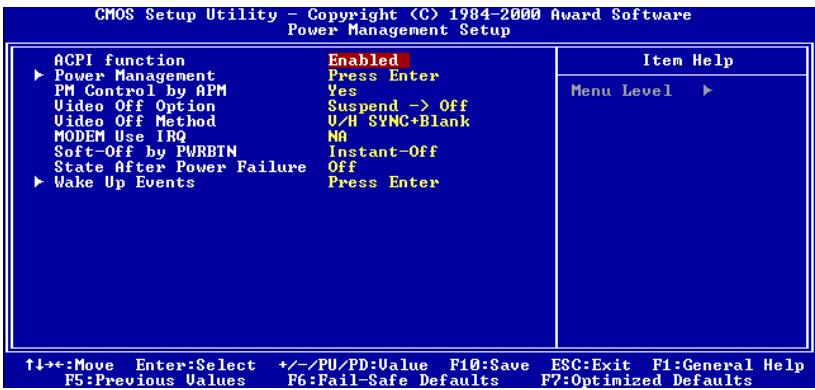
Figure 3-7A. Power Management Setup Main Menu
- Use the arrow keys to go to the item you want to configure. To change the settings, use PgUP, PgDn, + or - key.
- After you have configured the Power Management feature, press Esc to go back to the Main Menu.
We are now going to briefly explain the options in this menu:
ACPI Function (Advanced Configuration and Power Interface):
ACPI gives the operating system direct control over the power management and Plug and
Play functions of a computer.
If you want ACPI functions to work normally, you should notice two things. One is your operating system must support ACPI, as of now only Microsoft® Windows® 98 supports these functions. The second thing is that all devices and add-on cards in your system, must fully support ACPI, both hardware and software (drivers). If you want to know if your devices or add-on cards support ACPI or not, please contact the device or add-on card manufacture for more information. If you want to know more about ACPI specifications, please go to the address below for more detailed information:
http://www.teleport.com/~acpi/acpihtml/home.htm
ACPI requires an ACPI-aware operating system. ACPI features include:
- Plug and Play (including bus and device enumeration) and APM functionality normally contained in the BIOS.
- Power management control of individual devices, add-in cards (some add-in cards may require an ACPI-aware driver), video displays, and hard disk drives.
- A Soft-off feature that enables the operating system to power off the computer.
Support for multiple wake up events (see Table 3-1). - Support for a front panel power and sleep mode switch. Table 3-2 describes the system states based on how long the power switch is pressed, depending on how ACPI is configured with an ACPI-aware operating system.
Note
If you enable the ACPI function in the BIOS setup, the SMI switch function will not work.
System States and Power States
Under ACPI, the operating system directs all system and device power state transitions. The operating system puts devices in and out of low-power states based on user preferences and knowledge of how devices are being used by applications. Devices that are not being used can be turned off. The operating system uses information from applications and user settings to put the system as a whole into a low-power state.
Table 3-1: Wake Up Device and Events
The table below describes which devices or specific events can wake the computer from specific states.
| These device/events can wake up the computer...... | ......from this state |
| Power switch | Sleeping mode or power off mode |
| RTC alarm | Sleeping mode or power off mode |
| LAN | Sleeping mode or power off mode |
| Modem | Sleeping mode or power off mode |
| IR command | Sleeping mode |
| USB | Sleeping mode |
| PS/2 keyboard | Sleeping mode |
| PS/2 mouse | Sleeping mode |
| Sleep button | Sleeping mode |
Table 3-2: Effect of Pressing the Power Switch
| If the system is in this state...... | ......and the power switch is pressed for | ......the system enters this state |
| Off | Less than four seconds | Power on |
| On | More than four seconds | Soft off/Suspend |
| On | Less than four seconds | Fail safe power off |
| Sleep | Less than four seconds | Wake up |
Power Management:
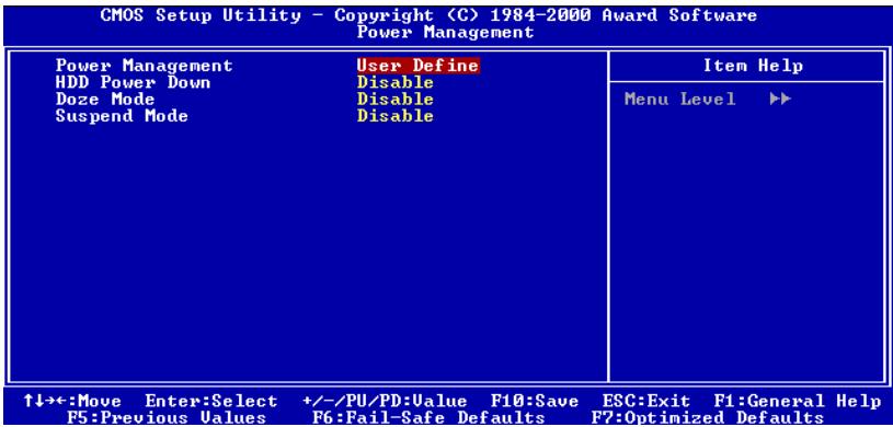
Figure 3-7B. Power Management Setup Menu
This item allows you to select the type (or degree) of power saving and is directly related to the following modes:
- HDD Power Down
- Doze Mode
- Suspend Mode
There are three options for power management, three of which have fixed mode settings:
User Define
"User Define" defines the delay for accessing the power modes.
HDD Power Down: Disabled 1 Min 2 Min 3 Min 4 Min 5 Min 6 Min 7 Min 8 Min 9 Hour 10 Min 11 Min 12 Min 13 Min 14 Min 15 Min. The default setting is Disabled.
Doze Mode: Disabled 1 Min 2 Min 4 Min 6 Min 8 Min 10 Min 20 Min 30 Min 40 Min 1 Hour. The default setting is Disabled.
Suspend Mode: Disabled 1 Min 2 Min 4 Min 6 Min 8 Min 10 Min 20 Min 30 Min 40 Min 1 Hour. The default setting is Disabled.
HDD Power Down:
Sixteen items available: Disable 1 Min 2 Min 3 Min 4 Min 5 Min 6 Min 7 Min 8 Min 9 Min 10 Min 11 Min 12 Min 13 Min 14 Min 15 Min Back to Disable. The default setting is Disable.
If the system has not accessed data on the hard disk drive during the specified time period, the engine of the HDD will stop in order to save electricity. You can set 1 to 15 minutes or select Disable according to your use of the HDD.
Doze Mode:
Eleven items are available: Disabled 1 Min 2 Min 4 Min 6 Min 8 Min 10 Min 20 Min 30 Min 40 Min 1 Hour Back to Disable. The default setting is Disable.
When the setting selected for "Power Management" is "User Define", you can define for this mode any delay from 1 minute to 1 hour. If no power management event occurs during this time period, meaning that the computer is inactive during this period, the system will enter the Doze power saving mode. If this mode is disabled, the system will enter the next mode in the sequence (suspend mode).
Suspend Mode:
Eleven items are available: Disabled 1 Min 2 Min 4 Min 6 Min 8 Min 10 Min 20 Min 30 Min 40 Min 1 Hour Back to Disable. The default setting is Disable.
When the setting selected for "Power Management" is "User Define", you can define for this mode any delay from 1 minute to 1 hour. If no power management event occurs during this time period, meaning the computer is inactive during this period, the system will enter the Suspend power saving mode. The CPU stops working completely.
If this mode is disabled, the system will not enter the suspend mode.
Min Saving
When these two saving modes are enabled, the system is set up for minimum power savings.
Doze Mode = 1 Hour
Suspend Mode = 1 Hour
Max Saving
When the two saving modes are enabled, the system is set up for maximum power savings.
Doze Mode = 1 Min
Suspend Mode = 1 Min
PM Control by APM:
Power Management is completely controlled by the APM.
Two options are available: Yes or No. The default setting is Yes. APM stands for Advanced
Power Management, it is a power management standard set by Microsoft®, Intel® and other major manufacturers.
Video Off Option:
Select the saving mode in which the video is switched off.
Always On
The video will never be switched off in the "no power saving" mode.
Suspend Off
The video will only be switched off in Suspend mode. (Default setting)
All Modes Off
The video will be switched off in all power saving modes.
Video Off Method:
Three video off methods are available: "Blank Screen", "V/H SYNC + Blank" and "DPMS Support". The default is "V/H SYNC + Blank".
If this setting does not shut off the screen, select "Blank Screen". If your monitor and video card support DMPS standard, select "DPMS Support".
Modem Use IRO:
Eight items available: 3 4 5 7 9 10 11 NA Back to 3. The default setting is NA . You can specify the IRQ for modem use.
Soft-Off by PWRBTN:
Two items available: Instant-Off or Delay 4 Sec. The default setting is Instant-Off. It is activated when the user presses the power button for more than four seconds while the system is in the working state, then the system will transition to the soft-off (Power off by software). This is called the power button over-ride.
State After Power Failure:
Three items are available: Auto On Off. The default setting is Off. If your computer power fails or an abnormal power shutdown occurs, the computer will return to either its previous state, the power on state, or the power off state.
Wake Up Events:
When one of the specified events occurs, the count down for entry into the power saving mode goes back to zero. Since the computer will enter a power saving mode only after a specified inactivity delay (time specific for Doze, Standby and Suspend modes) and after there has been no activity during this time period, any event will cause the computer to recount the time elapsed. Resume events are operations or signals that cause the computer to resume time counting.
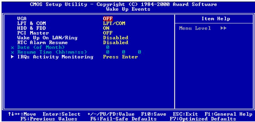
Figure 3-7C. Wake Up Events Setup Menu
VGA:
Two items available: On or Off. The default setting is Off. When set to On, any event occurring at a VGA port will awaken a system, which has been powered down.
LPT & COM:
Four items available: LPT/COM None LPT COM. The default setting is LPT/COM. When set to LPT/COM, any event occurring at a LPT (printer) / COM (serial) port will awaken a system which has been powered down.
HDD & FDD:
Two items available: On or Off. The default setting is On . When set to On, any event occurring at a hard disk drive or floppy drive port will awaken a system, which has been powered down.
PCI Master:
Two items available: On or Off. The default setting is Off. When set to On, any event occurring at PCI Master signal will awaken a system, which has been powered down.
> Wake Up On LAN/Ring:
Two items available: Disabled or Enabled. The default setting is Disabled. When set to Enabled, any event occurring to the LAN/Modem Ring will awaken a system, which has been powered down.
RTC Alarm Resume:
Two items available: Disabled or Enabled. The default setting is Disabled. When Enabled, your can set the date and time at which the RTC (real-time clock) alarm awakens the system from Suspend mode.
Date (of Month)/Timer (hh:mm:ss):
You could set the date (of month) and timer (hh:mm:ss), any event occurring at will awaken a system, which has been powered down.
IROs Activity Monitoring
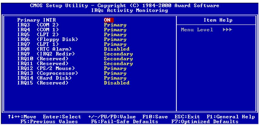
Figure 3-7D. IRQs Activity Monitoring Setup Menu
Primary INTR:
Two items available: On or Off. The default setting is On . When set to On, any event occurring at below list will awaken a system which has been powered down.
The following is a list of IRQ's, Interrupt ReQuests, which can be exempted much as the COM ports and LPT ports above can. When an I/O device wants to gain the attention of the operating system, it signals by causing an IRQ to occur. When the operating system is ready to respond to the request, it interrupts itself and performs the service.
As above, the choices are On and Off.
When set On, activity will neither prevent the system from going into a power management mode nor awaken it. Each item has three options: Primary Secondary Disabled.
IRQ3 (COM 2): The default setting is Primary.
IRQ4 (COM 1): The default setting is Primary.
IRQ5 (LPT 2): The default setting is Primary.
IRQ6 (Floppy Disk): The default setting is Primary.
IRQ7 (LPT 1): The default setting is Primary.
IRQ8 (RTC Alarm): The default setting is Disabled.
IRQ9 (IRQ2 Redir): The default setting is Secondary.
IRQ10 (Reserved): The default setting is Secondary.
IRQ11 (Reserved): The default setting is Secondary.
IRQ12 (PS/ 2 Mouse): The default setting is Primary.
IRQ13 (Coprocessor): The default setting is Primary.
IRQ14 (Hard Disk): The default setting is Primary.
IRQ15 (Reserved): The default setting is Disabled.
3-7. PNP/PCI Configurations Setup Menu
In this menu, you can change the INT# and IRQ of the PCI bus and other hardware settings.
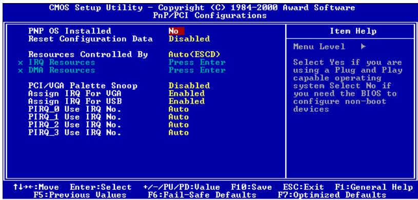
Figure 3-8A. PNP/PCI Configurations Setup Menu
PNP OS Installed:
Device resource assigned by PnP OS or BIOS. Two items available: Yes or No. The default setting is No.
Reset Configuration Data:
Two options are available: Disabled or Enabled. The default setting is Disabled. Normally, you leave this field Disabled. Select Enabled to reset Extended System Configuration Data (ESCD) when you exit Setup if you have installed a new add-on and the system reconfiguration has caused such a serious conflict that the operating system cannot boot.
Computer Knowledge: ESCD (Extended System Configuration Data)
The ESCD contains the IRQ, DMA, I/O port, memory information of the system. This is a specification and a feature specific to the Plug & Play BIOS.
Resources Controlled By:
When resources are controlled manually, assign each system interrupt as one of the following types, depending on the type of device using the interrupt:
Legacy ISA devices compliant with the original PC AT bus specification, requiring a specific interrupt (such as IRQ4 for serial port 1).
PCI/ISA PnP devices compliant with the Plug and Play standard, whether designed for the PCI or ISA bus architecture.
Two options are available: Auto (ESCD) or Manual. The default setting is Auto (ESCD).
The Award Plug and Play BIOS has the capability to automatically configure all of the boot and Plug and Play compatible devices. If you select Auto (ESCD), all of the interrupt request (IRQ) and DMA assignment fields disappear, as the BIOS automatically assigns them. But if you have trouble in assigning the interrupt resource automatically, you can select Manual to set which IRQ and DMA are assigned to PCI/ISA PnP or legacy ISA cards.
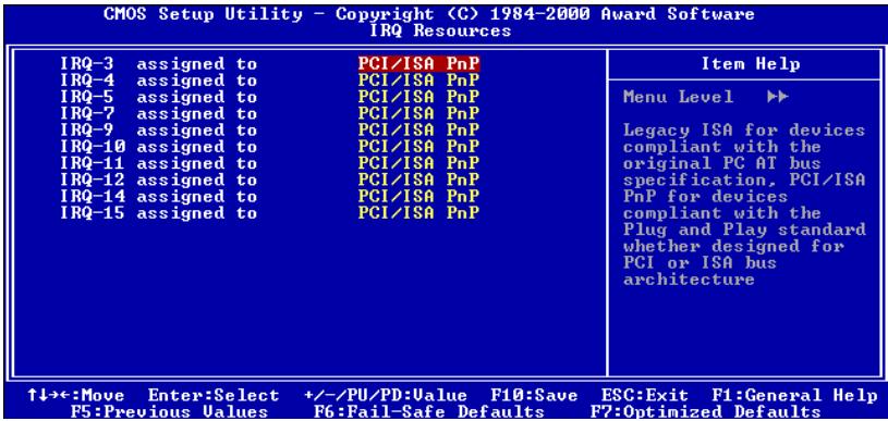
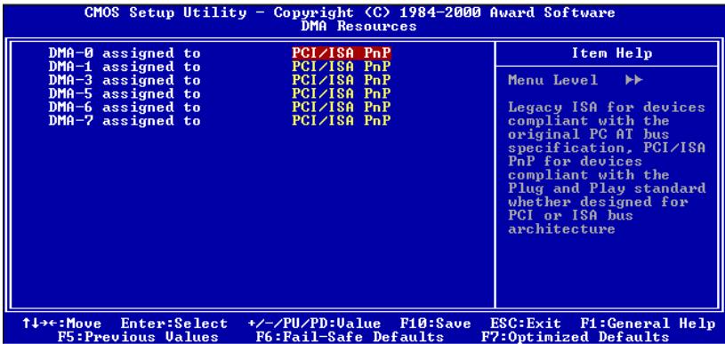
Figure 3-8B. IRQ Resources Setup Menu
Figure 3-8C. DMA Resources Setup Menu
PCI/VGA Palette Snoop:
This option allows the BIOS to preview VGA Status, and to modify the information delivered from the Feature Connector of the VGA card to the MPEG Card. This option can solve the display inversion to black after you have used the MPEG card.
Assign IRQ For VGA :
Two options are available: Disabled or Enabled. The default setting is Enabled. Name the interrupt request (IRQ) line assigned to the USB/VGA/ACPI (if any) on your system. Activity of the selected IRQ always awakens the system.
You can assign an IRQ for the PCI VGA or Disabled.
Assigned IRQ For USB:
Two options are available: Disabled or Enabled. The default setting is Enabled. If you need another IRQ to be freed up, you can choose to disable this item, and you can get an IRQ. But in some situations in Windows® 95 it may cause the USB port to malfunction or have other problems! Two options are available: Enable or Disable.
INT Pin 1 Assignment INT Pin 4 Assignment:
Eleven options are available: Auto, 3, 4, 5, 7, 9, 10, 11, 12, 14, 15. Default setting is Auto. This item allows the system to automatically specify the IRQ number for the device installed on PCI slots. Which means, the system can specify the fixed IRQ number for the device installed on the PCI slots (PCI slot 1 to PCI slot 5). This is a useful function when you want to fix the IRQ for a specific device.
For example, if you want to move your hard disk to another computer and don't want to re-install Windows NT, then you can specify the IRQ for the device installed on the new computer to fit the original computer settings.
Note
If you specify the IRQ in this item, then you cannot specify the same IRQ to the ISA bus, otherwise, it will cause a hardware conflict.
This feature is for the operating system which will record and fix the PCI configuration status, if you want to change it.
For the relations between the hardware layout of PIRQ (the signals from the VIA VT82C686A chipset), INT# (means PCI slot IRQ signals) and devices, please refer to the table below:
| Signals | PCI slot 1 | PCI slot 2 | PCI slot 3 | PCI slot 4 PCI slot 5 |
| INT Pin 1 Assignment | INT A | INT B | INT C | INT D |
| INT Pin 2 Assignment | INT B | INT C | INT D | INT A |
| INT Pin 3 Assignment | INT C | INT D | INT A | INT B |
| INT Pin 4 Assignment | INT D | INT A | INT B | INT C |
- USB used INT D.
Each PCI slot has four INT#s (INT Pin 1 ~ INT Pin 4), and the AGP slot has two INT# (INTA and INT B).
3-8. PC Health Status
You can check the fan speeds and power supply voltages of your computer system. The features are useful for monitoring all the important parameters within your computer system. We call it the PC Health Status.
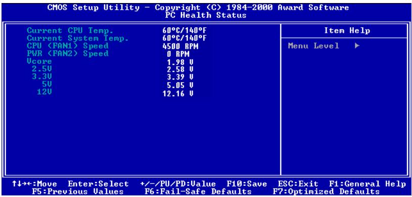
Figure 3-9. PC Health Status Screen Shot
All Voltages, Fans Speed and Thermal Monitoring:
These items list the current states of the CPU and environment (using RT1 and RT2 to detect them.) temperatures as well as fan speeds (CPU fan and power fan). It can not be changed by the user.
The following items list the voltage states of the system power. It is also unchangeable.
Note
The hardware monitoring features for temperatures, fans and voltages will occupy the I/O address from 294H to 297H. If you have a network adapter, sound card or other add-on cards that might use those I/O addresses, please adjust your add-on card I/O address, to avoid the use of those addresses.
3-9. Load Fail-Safe Defaults
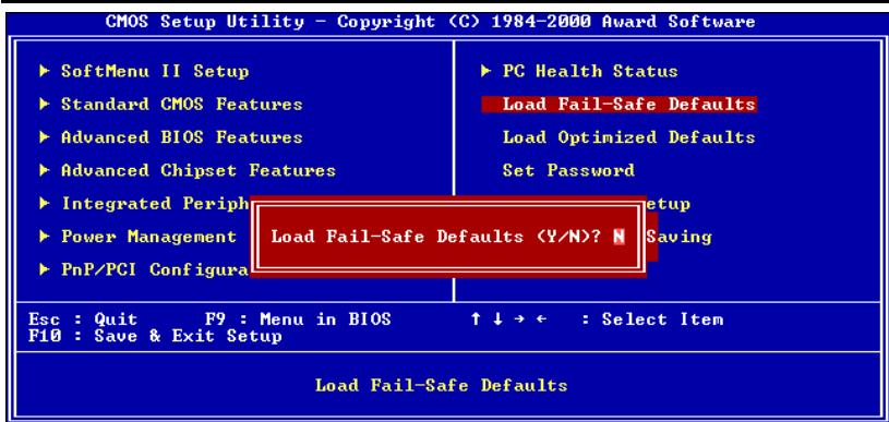
Figure 3-10. Load Fail-Safe Defaults Screen Shot
When you press
Load Fail-Safe Defaults (Y/N)? N
Pressing 'Y' loads the BIOS default values for the most stable, minimal-performance system operations.
3-10. Load Optimized Defaults
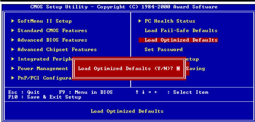
Figure 3-11. Load Optimized Defaults Screen Shot
When you press
Load Optimized Defaults (Y/N)? N
Pressing 'Y' loads the default values that are factory settings for optimal performance system operations.
3-11. Set Password
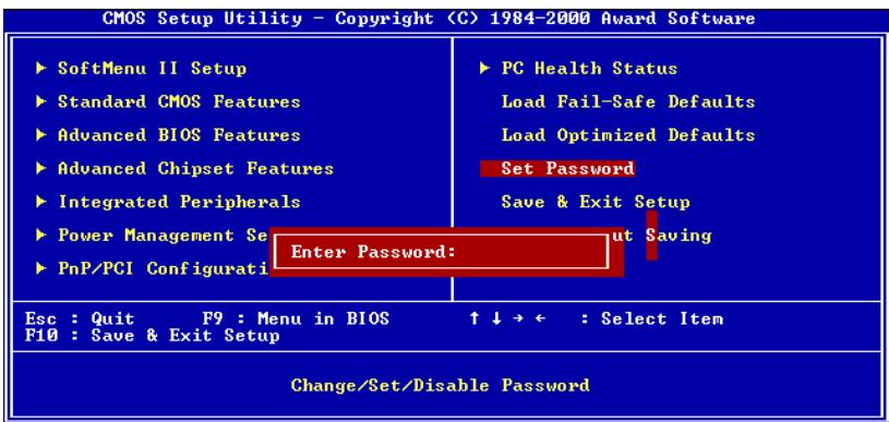
Figure 3-12. Set Password Screen Shot
Set Password: Can enter but do not have the right to change the options of the setup menus. When you select this function, the following message will appear at the center of the screen to assist you in creating a password.
ENTER PASSWORD:
Type the password, up to eight characters in length, and press
To disable a password, just press
TOKEN DISABLED.
When a password has been enabled, you will be prompted to enter it every time you try to enter Setup. This prevents an unauthorized person from changing any part of your system configuration.
Additionally, when a password is enabled, you can also require the BIOS to request a password every time your system is rebooted. This would prevent unauthorized use of your computer.
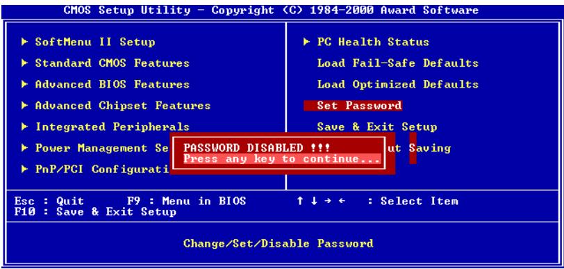
Figure 3-13. Password Disabled Screen Shot
You determine when the password is required within the BIOS Features Setup Menu and its Security option. If the Security option is set to "System", the password will be required both at boot and at entry to Setup. If set to "Setup", prompting only occurs when trying to enter Setup.
3-12. Save & Exit Setup
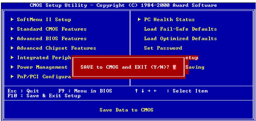
Figure 3-14. Save & Exit Setup Screen Shot
Pressing <Enter> on this item asks for confirmation:
Save to CMOS and EXIT (Y/N)? Y
Pressing "Y" stores the selections made in the menus in CMOS - a special section of memory that stays on after you turn your system off. The next time you boot your computer, the BIOS configures your system according to the Setup selections stored in CMOS. After saving the values the system is restarted again.
3-13. Exit Without Saving
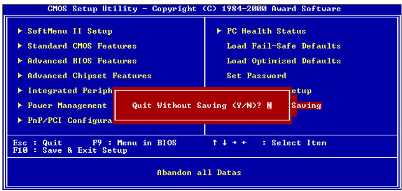
Figure 3-15. Exit Without Saving Screen Shot
Pressing <Enter> on this item asks for confirmation:
Quit without saving (Y/N)? Y
This allows you to exit Setup without storing in CMOS any change. The previous selections remain in effect. This exits the Setup utility and restarts your computer.
Appendix A. Installing the VIA Service Pack Drivers for Windows® 98 SE
After you've installed Windows® 98, you need to install the VIA Service Pack drivers. We will tell you step by step in the following section how to do this.
Note A-1
You have to install the VIA Service Pack drivers before you install the VGA and audio drivers. After installing Windows® the quality of your display will be poor because it will be set to 640480 and 16 color. For the best screen capture quality, install the VGA drivers and set the desktop to 800600 using True Color.
Note A-2
Details of the Windows® 98 SE operating system will not be mentioned in this manual. If you have any problems with Windows® 98 SE installation, operations and settings please refer to your Windows® 98 SE user's manual or other databases provided by Microsoft® Corporation.
First, go to check the System Properties Device Manager. We will show you several places that identify the VIA chipset and controller. Some items will illicit questions. (We'll discuss the VIA PCI Audio drivers installation in next chapter.)
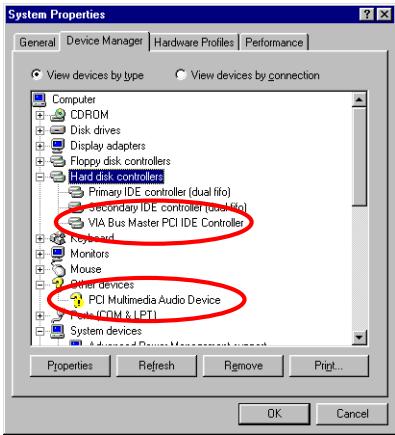
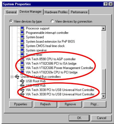
Exit the device manager and insert the VL6 CD-Title into your CD-ROM drive, it should execute the program automatically. If not, you can go to the CD location and execute the execution file at the main directory of this CD-Title. After it has been executed you will see the screen below.
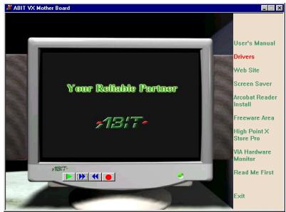
Move the cursor to "Drivers" and click on it.
You will go to the next screen.
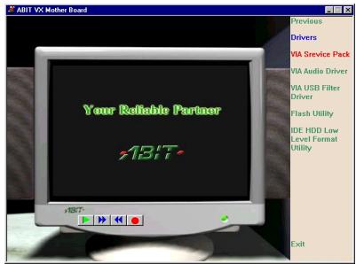
Move the cursor to "VIA Service Pack" and click on it. Go to the next screen.
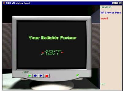
Move the cursor to "Install" and click on it.
Go to the next screen.
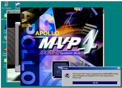
Now you will see the install shield loading.
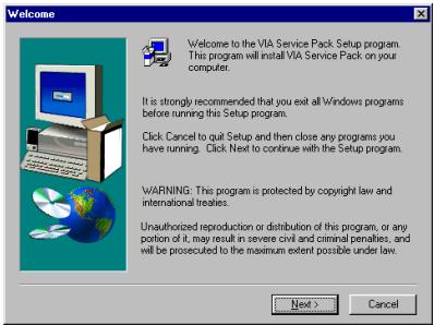
You will now see the welcome screen and its dialogue box. Click "Next" to go on.
The service pack readme screen will appear. Click the "Yes" button to go on.
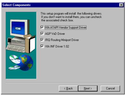
This setup program will install the four kinds of drivers. Please check which drivers you want to install. When you choose the items, please click the "Next" button to continue.
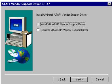
Choose the "Install VIA ATAPI Vendor Support Driver" and click the "Next> button to go on.

Choose "enable DMA Mode" and then click the "Next>" button.
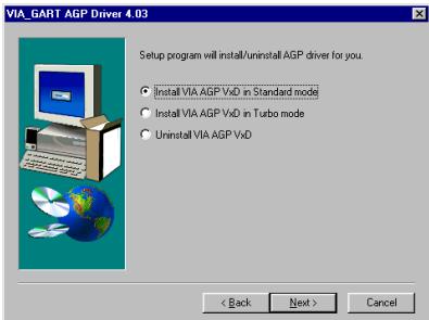
Choose the "Install VIA AGP VxD in Standard mode" and then click the "Next>" button.
Note A-3: What is the difference between "Standard" & "Turbo" mode
Installing in "Turbo" mode will give your graphics card the enhanced speed and performance while "Standard" mode offers increased system stability.
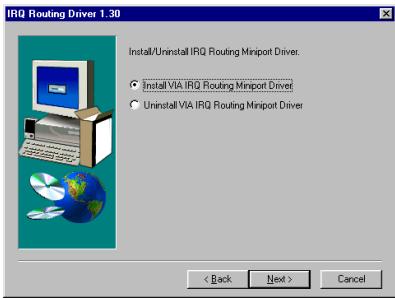
Choose "Install VIA Chipset Functions" Registry" and then click the > button.
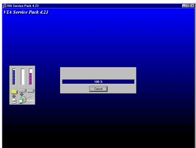
The installer will show the install progress percentage.

When the installation is complete, the installer will ask you to restart your computer. We suggest that you choose "Yes, I want to restart my computer now" and then click the "Finish" button to restart your computer to finish the driver installation.
When your computer system restarts, you will see the Windows® 98 SE starts the update process and several new hardware devices will be found and updated. When restarting Windows® 98 SE, the CD-ROM drives will fail to be found in the updating process. If the prompt dialogue box asks you to put the Windows® 98 SE CD into the CD-ROM drive, just ignore this message and let it go to the next process.
Go to check the System Properties Device Manager. It will show you several places that identify the VIA chipset and controller.
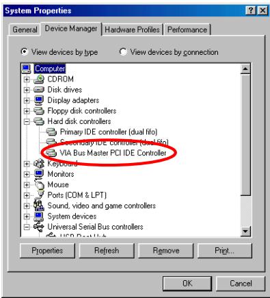
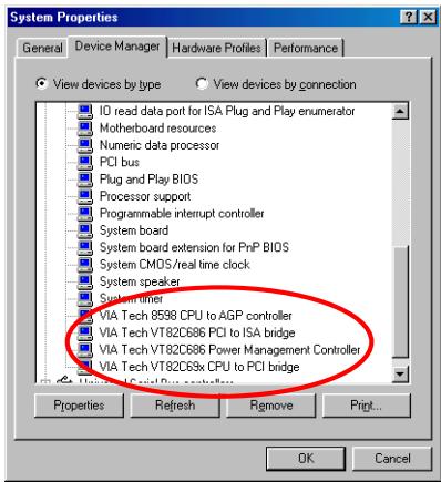
Problem under Windows® 95 OSR2
If your operating system is Windows® 95 OSR2, install the VIA service pack and Microsoft® usbsupp.exe for USB devices support. Then restart Windows and go to System Properties Device Manager. There will be question marks before "PCI Universal Serial Bus" and "VIA PCI to USB Universal Host Controller".
To make these question marks disappear, remove these items and then restart Windows. When Windows completes loading, these devices will returned to normal and the question marks will be gone.
Appendix B. Installing the VIA PCI Audio Driver for Windows® 98 SE
We will show you how to install the VIA PCI audio drivers for Windows® 98 SE operating system.
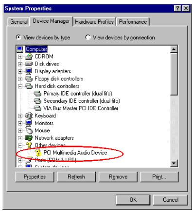
First check System Properties Device Manager Sound, Video and game controllers. Your system should now show "PCI Multimedia Audio Device".
Exit the Device Manager and insert the VL6 CD-Title into your CD-ROM drive. It should execute the program automatically. If not, you can go to the CD location and execute the execution file from the main directory of this CD-Title. Once executed, you will see the screen below.
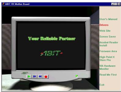
Move the cursor to "Drivers" and click on it. This will bring you to the next screen.

Move the cursor to "VIA Audio Driver" and click on it. Go to the next screen.
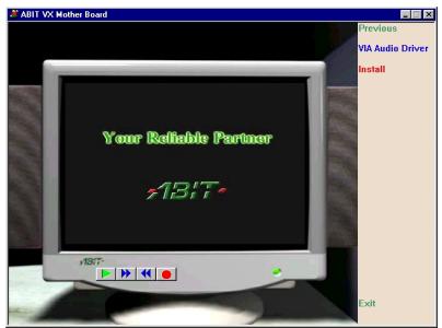
Move the cursor to "Install" and click on it.
Go to the next screen.

Now you will see the install shield loading.
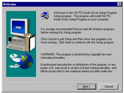
You will now see the welcome screen and its dialogue box. Click "Next" to go on.
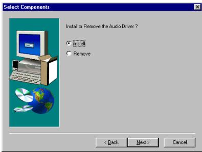
Choose "Install" and then click the "Next> button to go on.
Program will start to install all drivers you choose.
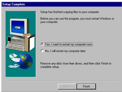
When installation is complete, the installer will ask you to restart your computer. We suggest you choose "Yes, I want to restart my computer now" and then click the "Finish" button to restart your computer to finish the drivers update.
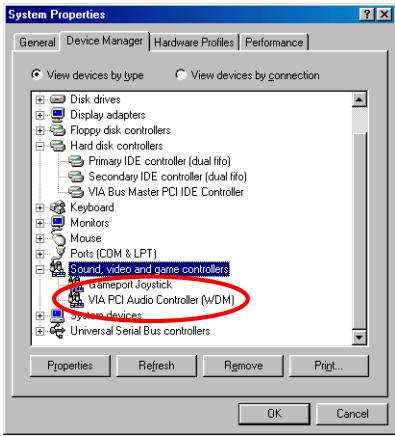
When Windows restarts, it will ask you to put the Windows® 98 SE CD into the CD-ROM drive. Put the Windows® 98 SE CD into the drive and follow the instructions to proceed.
When the update is finished, go to System Properties Device Manager Sound, Video and game controllers. Your system should now show "VIA PCI Audio Controller (WDM)" is there instead.

Appendix C. Installing the VIA USB Filter Driver for Windows® 98 SE
We will show you how to install the VIA USB filter drivers for Windows® 98 SE operating system.

Move the cursor to "Drivers" and click on it.
You will go to the next screen.
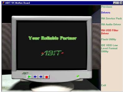
Move the cursor to "VIA USB Filter Driver" and click on it. Go to the next screen.
Move the cursor to "Install" and click on it.
Go to the next screen.

The installer will show the install progress percentage.

You will now see the welcome screen and its dialogue box. Click "Next" to go on.
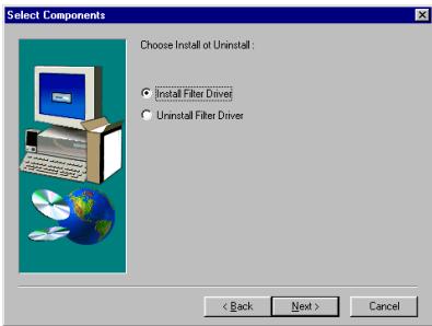
Choose the "Install Filter Driver" and then click the "Next> button to go on.
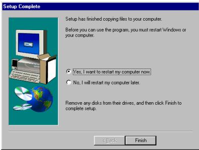
When the installation is complete, the installer will ask you to restart your computer. We suggest that you choose "Yes, I want to restart my computer now" and then click the "Finish" button to restart your computer to finish driver installation.
Appendix D. Installing the VIA Service Pack Drivers for Windows® NT 4.0 Server / Workstation
In this section we will show you how to install the VIA Service Pack drivers to your Windows NT 4.0 Server/Workstation operating system. All the screen shots are taken from the Windows NT 4.0 server version. Before you install the VIA Service Pack drives, please install Windows NT 4.0 Service Pack 5 (or latest version) first, and then you can install the VIA Service Pack drivers.
Note D-1
Details of the Windows NT 4.0 Server/Workstation operating system are not mentioned in this manual. If you have any problems with the settings, operating or installing Windows NT 4.0 Server/Workstation, please refer to your Windows NT 4.0 Server/Workstation user's manual or other databases provided by Microsoft Corporation.
Note D-2
For Windows NT 4.0 Server/Workstation operating system, you don't need to install the IDE-USB drivers. All you have to install is the Windows NT 4.0 Service Pack 5 (or latest version) first.
Insert the VL6 CD-Title into your CD-ROM drive. It should execute the program automatically. If not, you can go to the CD location and execute the execution file from the main directory of this CD-Title. After it is executed, you will see the screen below.
Move the cursor to "Drivers" and click on it. This will bring you to the next screen.
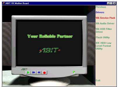
Move the cursor to "VIA Service Pack" and click on it. Go to the next screen.

Move the cursor to "Install" and click on it.
Go to the next screen.
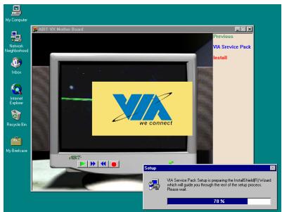
The install shield is now loading.
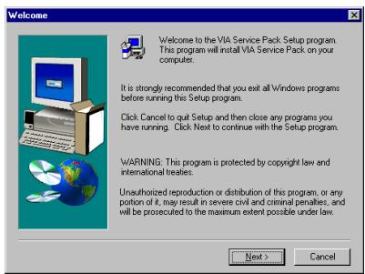
The "Welcome" screen and its dialogue box appear. Click the "Next" button to go on.
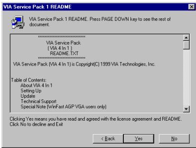
The readme screen will appear next. Click the "Yes" button to continue.
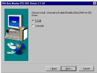
Choose "Install" and then click the "Next> button to go on.
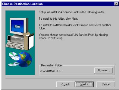
Now you can choose the folder for the destination location you want the drivers installed. We suggest you use the default folder as the destination location. After checking the folder click "Next> button.
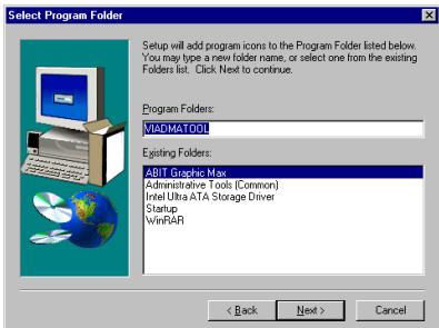
You can choose the name of the program folder. We suggest you use the default program folder name. After checking the program folder name then click "Next>" button.
Program will start to install drivers system need.
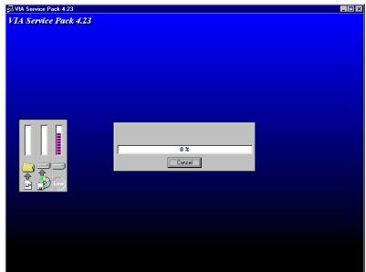
The installer will show the install progress percentage.
When installation is complete, the installer will ask you to restart your computer. We suggestion you choose "Yes, I want to restart my computer now" and then click "Finish" button to restart your computer to finish the drivers updating.
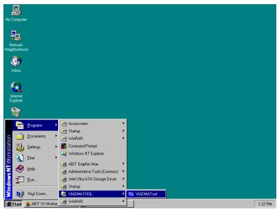
When you restart the Windows, you can see the VIA DMA Tools program group.
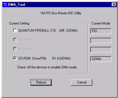
You can see the detail about your IDE device.
Appendix E. Installing the VIA PCI Audio Drivers for Windows® NT 4.0 Server / Workstation
In this section we will show you how to install the VIA PCI audio drives to your Windows NT 4.0 Server/Workstation operating system. All screen shots are from the Windows NT 4.0 server version. Before you install the VIA PCI audio drivers, please install Windows NT 4.0 Service Pack 5 (or the latest version) first. Then you can install the audio drivers.
Note E-1
Details of the Windows NT 4.0 Server/Workstation operating system are not mentioned in this manual. If you have any problems with the settings, operating or installing Windows NT 4.0 Server / Workstation, please refer to your Windows NT 4.0 Server/Workstation user's manual or other databases provided by Microsoft Corporation.
Note E-2
For Windows® NT 4.0 Server/Workstation operating system, you don't need to install the IDE-USB drivers. But you have to install the Windows® NT 4.0 Service Pack 5 (or latest version) first.
Insert the VL6 CD-Title into your CD-ROM drive. It should execute the program automatically. If not, you can go to the CD location and execute the execution file from the main directory of this CD-Title. Once executed, you will see the screen below.
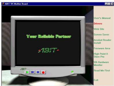
Move the cursor to "Drivers" and click on it. This will bring you to the next screen.

Move the cursor to "VIA Audio Driver" and click on it. Go to the next screen.
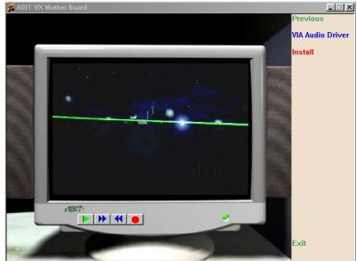
Move the cursor to "Install" and click on it. Go to the next screen.
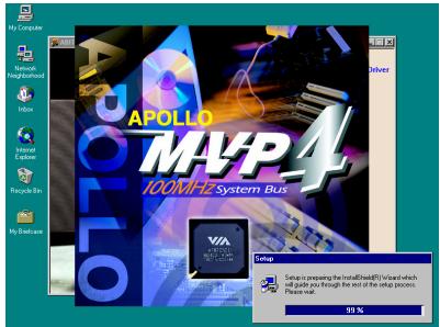
Now you will see the install shield loading.
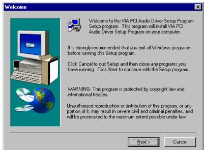
You will now see the welcome screen and its dialogue box. Click "Next" to go on.
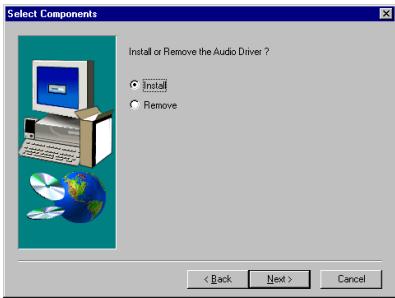
Choose "Install" then click the "Next>" button to go on.
Program will start to install all drivers you choose.
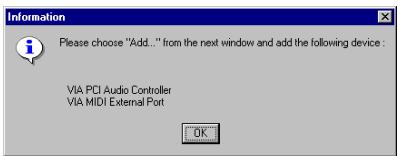
The dialogue box will show "Please choose "Add..." from the...", please click "OK" button to go on.
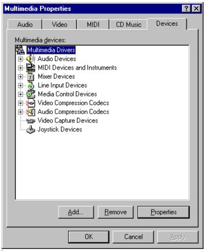
Choose "Add..." and then go to next screen.
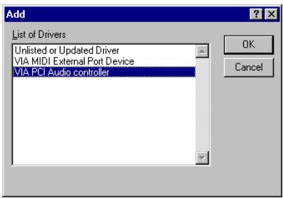
First, choose the "VIA PCI Audio Controller", then click "OK" button.
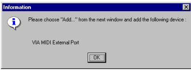
The dialogue box will show "Please choose "Add..." from...", this time will ask you to install the "VIA MIDI External Port". Please click "OK" button then go on.
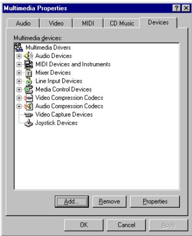
Choose "Add..." then go to next screen.
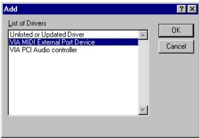
First, choose the "VIA MIDI External Port Device", then click "OK" button.

Program will ask if you want to install the Microsoft sidewinder 3D pro joystick driver. If you have this kind of joystick click "Yes", otherwise just click the "No" button to go on.

When installation is complete, the installer will ask you to restart your computer. We suggest that you choose "Yes, I want to restart my computer now" then click "Finish" button to restart your computer to finish the driver update.
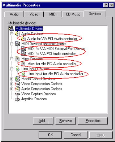
When Windows NT restarts, check the "Multimedia Properties". You will see the VIA PCI Audio devices had been identify.
Note E-3
If you are using the PCI bus mastering network adapter in your system under Windows NT 4.0, insert the network adapter into any PCI slot except slot 3. Otherwise, a system conflict may occur.

Appendix F. Installing the VIA Service Pack Drivers for Windows® 2000
After you've installed Windows® 2000 operation system, you need to install the VIA Service Pack drivers. We will tell you step by step in the following section how to do this.
Note F-1
You have to install the VIA Service Pack drivers before you install the VGA and audio drivers. After installing Windows® the quality of your display will be poor because it will be set to 640480 and 16 color. For the best screen capture quality, install the VGA drivers and set the desktop to 800600 using True Color.
Note F-2
Details of the Windows® 2000 operating system are not mentioned in this manual. If you have any problems with the settings, operating or installing Windows® 2000, please refer to your Windows® 2000 user's manual or other databases provided by Microsoft® Corporation.
First, go to check the System Properties Device Manager. We will show you several places that identify the VIA chipset and controller. Some items will illicit questions. (We'll discussion the VIA PCI Audio drivers installation in next chapter.)
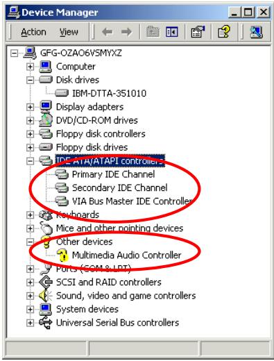
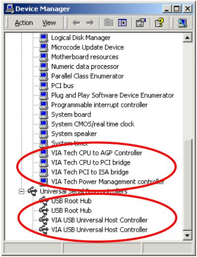
Exit the device manager and insert the VL6 CD-Title into your CD-ROM drive, it should execute the program automatically. If not, you can go to the CD location and execute the execution file at the main directory of this CD-Title. After it has been executed you will see the screen below.

Move the cursor to "Drivers" and click on it.
You will go to the next screen.
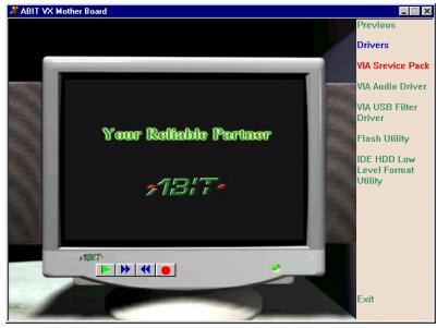
Move the cursor to "VIA Service Pack" and click on it. Go to the next screen.
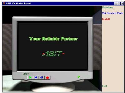
Move the cursor to "Install" and click on it.
Go to the next screen.
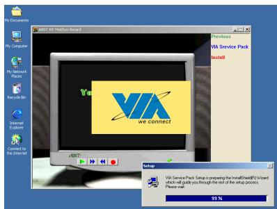
The install shield is now loading.
The welcome screen and its dialogue box appear. Click "Next" to go on.
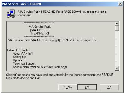
The service pack readme screen appears. Click the "Yes" button to go on.
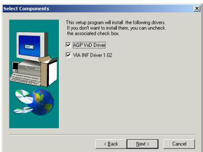
This setup program will install the drivers. Please check which drivers you want to install. After chosen the items, click the "Next>" button to continue.
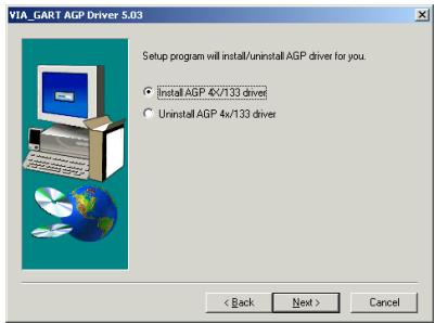
Choose the "Install AGP 4X/133 driver" and then click the "Next" button to go on.
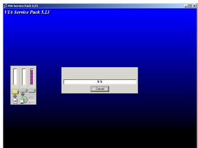
The installer will show the install progress percentage.
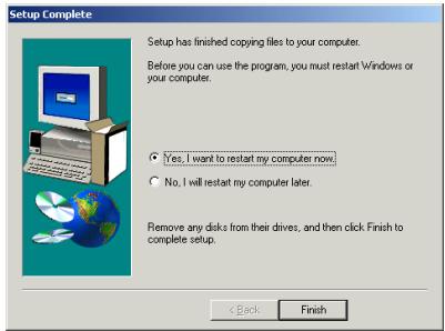
When the installation is complete, the installer will ask you to restart your computer. Choose "Yes, I want to restart my computer now" then click the "Finish" button to restart your computer to finish the driver installation.
Appendix G. Installing the VIA PCI Audio Drivers for Windows® 2000
In this section we will show you how to install the VIA PCI audio drives to your Windows® 2000 operating system. All screen shots are taken from the Windows® 2000 version.
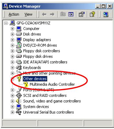
First check System Manager Other devices. Your system should now show the question mark before item "Multimedia Audio Controller".
Insert the VL6 CD-Title into your CD-ROM drive. It should execute the program automatically. If not, you can go to the CD location and execute the execution file from the main directory of this CD-Title. Once executed, you will see the screen below.
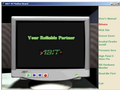
Move the cursor to "Drivers" and click on it. This will bring you to the next screen.
Move the cursor to "VIA Audio Driver" and click on it. Go to the next screen.
Move the cursor to "Install" and click on it.
Go to the next screen.

Now you will see the install shield loading.
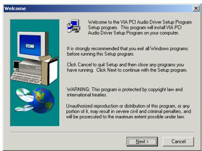
You will now see the welcome screen and its dialogue box. Click "Next" to go on.
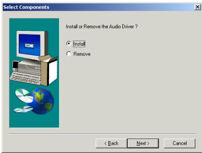
Choose "Install" then click the "Next>" button to go on.
Program will start to install all drivers you choose.
When installation is complete, the installer will ask you to restart your computer. We suggest that you choose "Yes, I want to restart my computer now" then click "Finish" button to restart your computer to finish the driver installation.
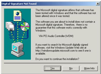
When Windows® 2000 restarts, it will start updating your audio drivers. When the "Digital Signature Not Found" screen appears, click "Yes" to go on. The program will then finish the updating.
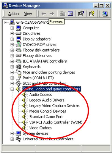
Finally, check the System Manager "Sound, video and game controllers". You will see the "VIA PCI Audio Controller (WDM)" is now identified.
Note
If you are using the PCI bus mastering network adapter in your system under Windows® 2000, insert the network adapter into any PCI slot except slot 3. Otherwise, a system conflict may occur.
Appendix H. Installing the VIA USB Filter Driver for Windows® 2000
We will show you how to install the VIA USB filter driver for Windows® 2000 operating system.
Move the cursor to "Drivers" and click on it.
You will go to the next screen.
Move the cursor to "VIA USB Filter Driver" and click on it. Go to the next screen.
Move the cursor to "Install" and click on it.
Go to the next screen.
The installer will show the install progress percentage.
You will now see the welcome screen and its dialogue box. Click "Next" to go on.

Choose the "Install Filter Driver", then click the "Next" button to go on.

When the installation is complete, the installer will ask you to restart your computer. We suggest that you choose "Yes, I want to restart my computer now" then click the "Finish" button to restart your computer to finish the driver updates.
Appendix I. BIOS Flashing User Instructions
When your motherboard needs to be upgraded with new features or some compatibility problems in the BIOS need to be fixed, you will need to use this BIOS flash utility. This utility is provided by Award Software makes it easy to flash by you. However, please read all the information in this section before flashing.
Before you can flash the BIOS you need to go into the pure DOS environment by rebooting your system and going directly into DOS. Basically, there are two ways to flash your BIOS. One is to directly type the full line commands that are described in this section. The utility will then flash your BIOS. When you finish the flash operation, you will see the screen as in Figure I-2 Note I-1.
The other method is to just type awdflash (under Award flash BIOS utility directory) then press enter. The Flash Memory Writer V7.52C screen will appear. Please refer to Figure I-1 Note I-1. You need to type "NEWBIOS" (the file name or you can use another name if you choose) into the "File Name to Program", then press enter.

Figure I-1. Award Flash Memory Writer V7.52C Start Screen
When you have finished updating your BIOS, you will see the screen as in Figure I-2. You then need to press the F1 key to reset the system, or press the F10 key to exit the writer.
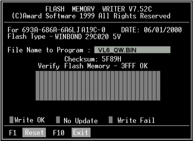
Figure I-3. Award Flash Memory Writer V7.52C Flash Commands Screen
Figure I-2. Award Flash Memory Writer V7.52C Complete Screen
Figure I-3 shows you what commands you can use for the flashing program. You need to go into the pure DOS environment and type awdflash. Figure I-3 will then appear.
Awdflash V7.52C(C)Award Software 1999 All Rights Reserved
Usage: AWDFLASH [FileName1] [FileName2] [/<sw>[/<sw>..]] FileName : New BIOS Name For Flash Programming FileName : BIOS File For Backing-up the Original BIOS <Switches> ?: Show Help Messages py: Program Flash Memory pn: No Flash Programming sy: Backup Original BIOS To Disk File sn: No Original BIOS Backup Sb: Skip BootBlock programming sd: Save DMI data to file cp: Clear PnP(ESCD) Data After Programming cd: Clear DMI Data After Programming cc: Clear CMOS Data After Programming R: RESET System After Programming kcs: Show update Binfile checksum Tiny: Occupy lesser memory E: Return to DOS When Programming is done F: Use Flash Routines in Original BIOS For Flash Programming LD: Destroy CMOS Checksum And No System Halt For First Reboot After Programming cksXXXX: Compare Binfile CheckSum with XXXX Example: AWDFLASH 2a59i000.bin /py/sn/cd/cp/cks2635
Note I-1
The BIOS file name in the figure shown is only an example. You should check which .bin file is to be used with your motherboard. Don't flash with the wrong .bin file otherwise you may cause system malfunctions. Even the same model BIOS, according to their release dates and which problems have been fixed, have different .bin names. Please read the BIOS file description before you download it.
For example, if you want to update the VL6 BIOS, please follow the procedures described below.
Step 1. Please visit our website (www.abit.com.tw) and download the following files: ABITFAE.BAT, AWDFLASH.EXE and the VL6's newest BIOS file--VL6_QW.EXE for example. After you download these three files, please execute the "VL6_QW.EXE." Then you will get a file "VL6_QW BIN."
Step 2. Create a bootable floppy without any resident programs, and then copy the files ABITFAE.BAT, AWDFLASH and VL6_QW.BIN to the floppy.
Step 3. Reboot your computer and enter the BIOS setup. Set your system to boot from "Floppy" (refer to section 3-3) and then insert the floppy you created into drive A.
Step 4. After you boot from floppy successfully, at the “A:>” prompt, execute the following command:
ABITFAE VL6_QW.BIN (Enter)
The BIOS will be updated automatically with all parameters.
Step 5. After the flash update is completed, reboot your system, and then go into the BIOS setup to configure the CPU parameter and other peripheral settings (refer to chapter 3).
Note I-2
- The Award flash utility can not be completed under a Windows® 95/98 or Windows NT environment, you must be in a pure DOS environment.
- You should check which BIOS file is to be used with your motherboard, don't flash with the wrong BIOS file. Otherwise, you may cause system malfunctions.
Note I-3
Please do not use the Award flash memory writer version that earlier than Version 7.52C to flash your VL6 motherboard BIOS. Otherwise, it may cause flash fail or anticipate problems.
Appendix J. Installing the VIA Hardware Monitor System
The VIA Hardware Monitor System is a self-diagnostic system for PCs. It will protect PC hardware by monitoring several critical items including power supply voltages, CPU & system fan speeds, and CPU and system temperatures. These items are important for the operation of the system; errors may result in permanent damage to the PC. Once any item is out of its normal range, a warning message will pop up and remind the user to take proper measures.
The following description will show you how to install the VIA Hardware Monitor System and use it. Insert the VL6 CD-Title into your CD-ROM drive. It should execute the program automatically. If not, you can go to the CD location and execute the execution file from the main directory of this CD-Title. After it is executed, you will see the screen below.
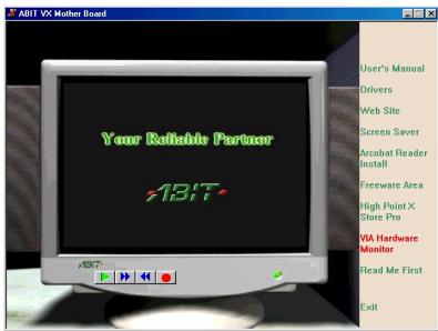
Click "VIA Hardware Monitor" button.
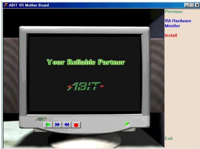
Click "Install" button to start install the VIA hardware monitor system utility.
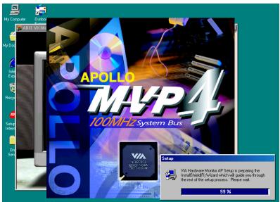
You will see the install shell active.
The "Welcome" screen and its dialogue box will appear. Click the "Next>" button to go on.
Now you can choose the folder for the destination location you want to install the drivers. We suggest you use the default folder as the destination location. After checking the folder click "Next> button.
You can choose the name of the program folder. We suggest you use the default program folder name. After checking the program folder name then click "Next> button.
Program will start to install drivers system need.
The installer will show the install progress percentage.
When installation is complete, the installer will automatically terminate the install process.
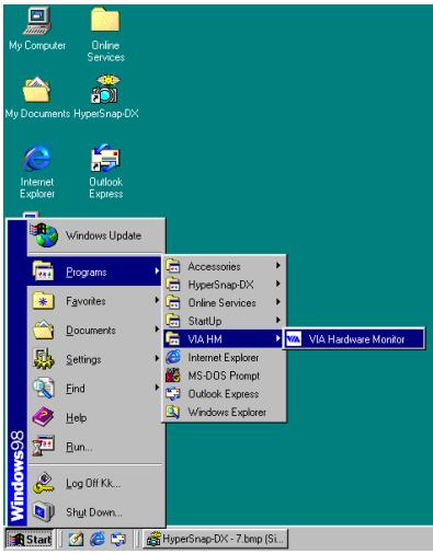
When installation is complete, choose "Programs" from the "Start" toolbar. You can see the program group "VIA HM" and an item called "VIA Hardware Monitor". Click it, and then you can see the screen below.
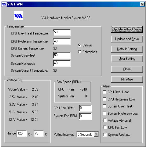
This screen shows the VIA hardware monitor system screen. It shows the information about system temperature, voltages and fan speed. Some items can let you set the warning range; you can accordance your system to make optimize value setting.
For Windows® NT Screen Shot:
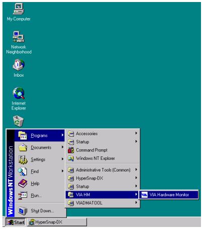
When installation is complete, choose "Programs" from the "Start" toolbar. You can see the program group "VIA HM" and an item called "VIA Hardware Monitor". Click it, and then you can see the same VIA HWM screen at the previous page.
For Windows® 2000 Screen Shot:
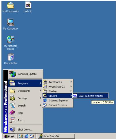
When installation is complete, choose "Programs" from the "Start" toolbar. You can see the program group "VIA HM" and an item called "VIA Hardware Monitor". Click it, and then you can see the same VIA HWM screen at the previous page.
Appendix K. Troubleshooting (Need Assistance?)
If you have a problem during operation, in order to help our technical support personnel quickly determine the problem with your motherboard and give you the answers you need, before filling in the technical support form, eliminate any peripheral that is not related to the problem, and indicate it on the form. Fax this form to your dealer or to the company where you bought the hardware in order to benefit from our technical support. (You can refer to the examples given below)

Example 1: With a system including: motherboard (with CPU, DRAM, COAST...) HDD, CD-ROM, FDD, VGA CARD, MPEG CARD, SCSI CARD, SOUND CARD, etc. After the system is assembled, if you cannot boot up, check the key components of the system using the procedure described below. First remove all interface cards except the VGA card and try to reboot.
If you still cannot boot up:
Try installing another brand/model VGA card and see if the system will start. If it still does not start, note the VGA card model, motherboard model, Bios identification number, CPU on the technical support form (refer to main instructions), and describe the problem in the problem description space provided.
If you can boot up:
Insert the interface cards you have removed back into the system, one by one and try to start the system each time you insert a card, until the system will not start. Keep the VGA card and the interface card that caused the problem inserted on the motherboard, remove any other cards or peripheral, and start again. If you still cannot start, note the information related to both cards in the add-on Card space provided, and don't forget to indicate the motherboard model, version, BIOS identification number, CPU (refer to main instructions), and give a description of the problem.

Example 2: With a system including the motherboard (with CPU, DRAM, COAST...) HDD, CD-ROM, FDD, VGA CARD, LAN CARD, MPEG CARD, SCSI CARD, SOUND CARD, after assembly and after having installed the Sound Card Driver, when you restart the system, when it runs the Sound Card Driver, it
resets automatically. This problem may be due to the Sound Card Driver. During the Starting DOS... procedure, press SHIFT (BY-PASS) key, to skip CONFIG.SYS and AUTOEXEC.BAT; edit CONFIG.SYS with a text editor, and in function the line that loads the Sound Card Driver, add a remark REM, in order to disable the Sound Card Driver. See the example below.
CONFIG.SYS:
DEVICE=C:\DOS\HIMEM.SYS
DEVICE=C:\DOS\EMM386.EXE HIGHSCAN
DOS=HIGH, UMB
FILES=40
BUFFERS=36
REM DEVICEHIGH=C:\PLUGPLAY\DWCFGMG.SYS
LASTDRIVE Z
Restart the system. If the system starts and does not reset, you can be sure that the problem is due to the Sound Card Driver. Write down the Sound Card model, motherboard model, BIOS identification number on the technical support file (refer to main instructions), and describe the problem in the space provided.
Main instructions...
To fill in this "Technical Support Form", refer to the step-by-step instructions given below:
1*.MODEL: Note the model number given in your user's manual.
Example: VH6, BX6, BH6, etc...
2. Motherboard model number (REV): Note the motherboard model number labeled on the motherboard as “REV:.**”.
Example: REV: 1.01
3*.BIOS ID and Part Number: See next page example.
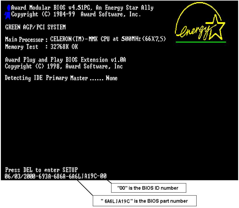
- DRIVER REV: Note the driver version number indicated on the DEVICE DRIVER disk (if have) as "Release .*". For example:
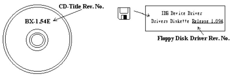
5*. OS/APPLICATION: Indicate the operating system and the applications your are running on the system.
Example: MS-DOS® 6.22, Windows® 95, Windows® NT....
6^* .CPU:Indicate the brand and the speed (MHz) of your CPU.
Example: (A) In the "Brand" space, write "Intel", in the "Specifications" space, write "Pentium® II MMX 300MHz".
- HDD: Indicate the brand and specifications of your HDD(s), specify if the HDD is using IDE1 or IDE2. If you know the disk capacity, indicate it and check ("✓") "□"; in case you give no indication, we will consider that your HDD is "☑IDE1" Master.
Example: In the "HDD" space, check the box, in the Brand space, write "Seagate", in the Specifications space, write "ST31621A (1.6GB)".
- CD-ROM Drive: Indicate the brand and specifications of your CD-ROM drive. Specify if it uses IDE1 or IDE2, and check ("✓") "□"; in case you give no indication, we will consider that your CD-ROM is "IDE2" Master.
Example: In the "CD-ROM drive" space, check the box, in the Brand space, write "Mitsumi", in the Specifications space, write "FX-400D".
- System Memory (DRAM): Indicate the brand and specifications (SIMM / DIMM) of your system memory. For example:
In the Brand space, write "Panasonic", in the Specifications space, write "SIMM-FP DRAM 4MB-06".
Or, in the Brand, write "NPNX", in the Specifications space, write "SIMM-EDO DRAM 8MB-06".
Or, in the Brand space, write "SEC", in the Specifications space, write "DIMM-S DRAM 8MB-G12".
- ADD-ON CARD: Indicate which add-on cards you are absolutely sure is related to the problem.
If you cannot identify the problem's origin, indicate all the add-on cards inserted into your system.
Note
Items between the ** are absolutely necessary.

Technical Support Form

Company Name:

Phone Number:

Contact Person:

Fax Number:

E-mail Address:
| Model | * | BIOS ID # | * |
| Motherboard Model No. | DRIVER REV | ||
| OS/Application | * | ||
| Hardware name | Brand | Specifications | |
| CPU | * | ||
| HDD IDE1 | |||
| IDE2 | |||
| CD- IDE1 | |||
| ROM IDE2 | |||
| Drive | |||
| System Memory (DRAM) | |||
| ADD-ON CARD | |||

Problem Description:

Appendix L. How to Get Technical Support
(From our website) http://www.ubit.com.tw
(In North America) http://www.ubit-usa.com
(In Europe) http://www.abet.nl
Thank you for choosing ABIT products. ABIT sells all our products through distributors, resellers and system integrators, we have no direct sales to end-users. Before sending email for tech support please check with your resellers or integrators if you need any services, they are the ones who sold you your system and they should know best as to what can be done, how they serve you is a good reference for future purchases.
We appreciate every customer and would like to provide the best service to you. Providing fast service to our customers is our top priority. However we receive many phone calls and a huge amount of email from all over the world. At the present time it is impossible for us to respond to every single inquiry. Therefore it is quite possible that if you send an email to us that you may not receive a response.
We have done many compatibility tests and reliability tests to make sure our products have the best quality and compatibility. In case you need service or technical support, please understand the constraint we have and always check with the reseller who sold the product to you first.
To expedite service, we recommend that you follow the procedures outlined below before contacting us. With your help, we can meet our commitment to provide the best service to the greatest number of ABIT customers:
- Check the Manual. It sounds simple but we have taken a lot of care in making a well-written and thorough manual. It is full of information that doesn't only pertain to motherboards. The CD-ROM included with your board will have the manual as well as drivers. If you don't have either one go to our Program Download Area of the website or FTP server at: http://www.abit.com.tw/download/index.htm
- Download latest BIOS, software or drivers. Please go to our Program Download area on our website to check to see if you have the latest BIOS. They are developed over periods of time to fix bugs or incompatibilities. Also please make sure you have the latest drivers from your peripheral cards makers!
-
Check the ABIT Technical Terms Guide and FAQ on our website. We are trying to expand and make the FAQs more helpful and information rich. Let us know if you have any suggestions. For hot topics check out our HOT FAQ!
-
Internet Newsgroups. They are a great source of information and many people there can offer help. ABIT's Internet News group, alt.comp.periphs.mainboard.abit, is an ideal forum for the public to exchange information and discuss experiences they have had with ABIT products. Many times you will see that your question has already been asked before. This is a public Internet news group and it is reserved for free discussions. Here is a list of some of the more popular ones:
alt.comp.perips.mainboard.abit
comp.sys.ibm.pc.hardware.chips
alt.comp.hardware.overlocking
alt.comp.hardware.homebuilt
alt.comp.hardware.pc-homebuilt
Ask your reseller. Your ABIT authorized distributor should be able to provide the fastest solution to your technical problem. We sell our products through distributors who sell to resellers and stores. Your reseller should be very familiar with your system configuration and should be able to solve your problem much more efficiently than we could. After all, your reseller regards you as an important customer who may purchase more products and who can urge your friends to buy from him or her as well. They integrated and sold the system to you. They should know best what your system configuration is and your problem. They should have reasonable return or refund policies. How they serve you is also a good reference for your next purchase.
- Contacting ABIT. If you feel that you need to contact ABIT directly you can send email to the ABIT technical support department. First, please contact the support team for the branch office closest to you. They will be more familiar with local conditions and problems and will have better insight as to which resellers offer what products and services. Due to the huge number of emails coming in every day and other reasons, such as the time required for problem reproduction, we will not be able to reply to every email. Please understand that we are selling through distribution channels and don't have the resources to serve every end-user. However, we will try to do our best to help every customer. Please also remember that for many of our technical support team English is a second language, you will have a better chance of getting a helpful answer if your question can be understood in the first place. Be sure to use very, simple, concise language that clearly states the problem, avoid rambling or flowery language and always list your system components. Here is the contact information for our branch offices:
In North America and South America please contact:
ABIT Computer (USA) Corporation
46808 Lakeview Blvd.
Fremont, California 94538 U.S.A.
sales@abit-usa.com
technical@abit-usa.com
Tel: 1-510-623-0500
Fax: 1-510-623-1092
In the UK and Ireland:
ABIT Computer Corporation Ltd.
Caxton Place, Caxton Way,
Stevenage, Herts SG1 2UG, UK
abituksales@compuserve.com
abituktech@compuserve.com
Tel: 44-1438-741 999
Fax: 44-1438-742 899
In Germany and Benelux (Belgium, Netherlands, Luxembourg) countries:
AMOR Computer B.V. (ABIT's European Office)
Van Coehoornstraat 5a,
5916 PH Venlo, The Netherlands
sales@abit.nl
technical@abit.nl
Tel: 31-77-3204428
Fax: 31-77-3204420
All other territories not covered above please contact:
Taiwan Head Office
When contacting our headquarters please note we are located in Taiwan and we are 8+ GMT time. In addition, we have holidays that may be different from those in your country.
ABIT Computer Corporation
3F-7, No. 79, Sec. 1, Hsin Tai Wu Rd.
Hsi Chi, Taipei Hsien
Taiwan, R.O.C.
sales@abit.com.tw
market@abit.com.tw
technical@abit.com.tw
Tel: 886-2-2698-1888
Fax: 886-2-2698-1811
RMA Service. If your system has been working but it just stopped, but you have not installed any new software or hardware recently, it is likely that you have a defective component. Please contact the reseller from whom you bought the product. You should be able to get RMA service there.
- Reporting Compatibility Problems to ABIT. Because of tremendous number of email messages we receive every day, we are forced to give greater weight to certain types of messages than to others. For this reason, any compatibility problem that is reported to us, giving detailed system configuration information and error symptoms will receive the highest priority. For the other questions, we regret that we may not be able to reply directly. But your questions may be posted to the Internet news group in order that a larger number of users can have the benefit of the information. Please check the news group from time to time.
Thank you, ABIT Computer Corporation http://www.abit.com.tw

- Copyright and Warranty Notice
- VL6 Motherboard User's Manual
- CHAPTER 1. INTRODUCTION OF VL6 FEATURES 1-1
- CHAPTER 2. INSTALLING THE MOTHERBOARD. 2-1
- CHAPTER 3. INTRODUCING THE BIOS 3-1
- APPENDIX A. INSTALLING THE VIA SERVICE PACK DRIVERS FOR WINDOWS® 98 SE
- APPENDIX B. INSTALLING THE VIA PCI AUDIO DRIVER FOR WINDOWS® 98 SE
- APPENDIX C. INSTALLING THE VIA USB FILTER DRIVER FOR WINDOWS® 98 SE
- Chapter 1. Introduction of VL6 Features
- 1-1. Features of This Motherboard
- 1-2. Specifications
- CPU
- Chipset
- Memory (System Memory)
- System BIOS
- Multi I/O Functions
- Audio CODEC Features
- Miscellaneous
- Note
- 1-3. Layout Diagram
- 1-4. The System Block Diagram
- Chapter 2. Installing the Motherboard
- Before Proceeding with the Installation
- User Friendly Instructions
- 2-1. Installing the Motherboard to the Chassis
- 2-2. Installation of the Intel® Celeron™ (PPGA & FC-PGA) & Pentium® III (FC-PGA) processors
- 2-3. Installing System Memory
- 2-4. Connectors, Headers and Switches
- ATXPWR1: ATX Power Input Connector
- Caution
- (2A)/(2B)/(2C): FAN1, FAN2 & FAN3 header
- IR: IR Header (Infrared)
- WOM1: Wake On Modem Header
- WOL1: Wake on LAN Header
- SMB1: System Management Bus Connector
- (7A)/(7B): RT1 & RT2 Thermister:
- USB2 Headers: Additional USB Plugs Header
- CDIN1: Internal CD-ROM Drive Audio Cable Header
- CCMOS1: CMOS Discharge Jumper
- J1 & J2 Headers:
- JP1 Header: AMR Function Selection
- PN1 and PN2 Headers
- PN1 (Pin 10-11): Hardware Suspend Switch (SMI Switch) Header
- PN2 (Pin 1-2): Hardware Reset Switch Header
- PN2 (Pin 4-5-6-7): Speaker Header
- FDC1 Connector
- IDE1 and IDE2 Connectors
- How to install the Ultra ATA/66 Cable Assembly:
- KM1 Lower: PS/2 Keyboard Connector
- KM1 Upper: PS/2 Mouse Connector
- USB Port Connectors
- Serial Port COM1 & COM2 Port Connector
- Parallel Port Connector
- Line Out, Line In and Mic In Connector
- MIDI/GAME Port Connector
- Chapter 3. Introducing the BIOS
- Don't change the parameters inside the BIOS unless you fully understand their meanings and consequences
- PRESS DEL TO ENTER SETUP
- Computer Knowledge: CMOS Data
- 3-1. CPU Setup [SOFT MENU™ II]
- CPU Name Is:
- CPU Operating Speed:
- User Defined
- Warning
- te
- Solution in case of booting problem due to invalid clock setup:
- When you change your CPU:
- Attention
- CPU Power Supply:
- Spread Spectrum:
- CPU Hardwired IOQ:
- 3-2. Standard CMOS Features Setup Menu
- Date (mm:dd:yy):
- Time (hh:mm:ss):
- IDE Primary Master / Slave and IDE Secondary Master / Slave:
- IDE HDD Auto-Detection:
- IDE Primary Master:
- Access Mode:
- Auto:
- Normal mode:
- LBA (Logical Block Addressing) mode:
- Large Mode:
- Capacity:
- Cylinder:
- Head:
- Precomp:
- Landing Zone:
- Sector:
- Driver A & Driver B:
- Floppy 3 Mode Support:
- Video:
- Halt On:
- 3-3. Advanced BIOS Features Setup Menu
- Virus Warning:
- CPU Level 1 Cache:
- CPU Level 2 Cache:
- CPU L2 Cache ECC Checking:
- Processor Number Feature
- Quick Power On Self Test:
- First Boot Device:
- Second Boot Device:
- Third Boot Device:
- Boot Other Device:
- Swap Floppy Drive:
- Boot Up Floppy Seek:
- Boot Up NumLock Status:
- Typematic Rate Setting:
- Typematic Rate (Chars/Sec):
- Typematic Delay (Msec):
- Security Option:
- Notice
- OS Select For DRAM >64MB
- Report No FDD For WIN 95:
- Video BIOS Shadow:
- Shadowing address ranges:
- Computer Knowledge: SHADOW
- Delay IDE Initial (Sec):
- 3-4. Advanced Chipset Features Setup Menu
- Bank 0/1, 2/3, 4/5 DRAM Timing:
- DRAM Bank Interleave:
- Delay DRAM Read Latch:
- SDRAM Cycle Length:
- DRAM Clock:
- Memory Hole:
- Read Around Write
- Concurrent PCI/Host
- System BIOS Cacheable:
- Video RAM Cacheable:
- AGP Aperture Size:
- AGP-2X Mode:
- CPU to PCI Write Buffer:
- PCI Dynamic Bursting:
- PCI Master 0 WS Write:
- PCI Delay Transaction:
- PCI#2 Access #1 Retry:
- AGP Master 1 WS Write:
- AGP Master 1 WS Read:
- OnChip Sound:
- OnChip Modem:
- Memory Parity/ECC Check:
- 3-5. Integrated Peripherals
- Onboard IDE-1 Controller:
- - Master Drive PIO Mode:
- - Slave Drive PIO Mode:
- Master Drive Ultra DMA:
- Onboard IDE-2 Controller:
- IDE Prefetch Mode:
- Init Display First:
- USB Controller:
- IDE HDD Block Mode:
- Onboard FDD Controller:
- Onboard Serial Port 1:
- Onboard Serial Port 2:
- Onboard IR Function:
- Onboard Parallel Port:
- Onboard Parallel Mode:
- 3-6. Power Management Setup Menu
- ACPI Function (Advanced Configuration and Power Interface):
- System States and Power States
- Table 3-1: Wake Up Device and Events
- Power Management:
- HDD Power Down:
- Doze Mode:
- Suspend Mode:
- PM Control by APM:
- Video Off Option:
- Video Off Method:
- Modem Use IRO:
- Soft-Off by PWRBTN:
- State After Power Failure:
- Wake Up Events:
- VGA:
- LPT & COM:
- HDD & FDD:
- PCI Master:
- > Wake Up On LAN/Ring:
- RTC Alarm Resume:
- IROs Activity Monitoring
- Primary INTR:
- 3-7. PNP/PCI Configurations Setup Menu
- PNP OS Installed:
- Reset Configuration Data:
- Computer Knowledge: ESCD (Extended System Configuration Data)
- Resources Controlled By:
- PCI/VGA Palette Snoop:
- Assign IRQ For VGA :
- Assigned IRQ For USB:
- INT Pin 1 Assignment INT Pin 4 Assignment:
- 3-8. PC Health Status
- All Voltages, Fans Speed and Thermal Monitoring:
- 3-9. Load Fail-Safe Defaults
- 3-10. Load Optimized Defaults
- 3-11. Set Password
- ENTER PASSWORD:
- TOKEN DISABLED.
- 3-12. Save & Exit Setup
- 3-13. Exit Without Saving
- Note A-1
- Note A-2
- Note A-3: What is the difference between "Standard" & "Turbo" mode
- Problem under Windows® 95 OSR2
- Appendix D. Installing the VIA Service Pack Drivers for Windows® NT 4.0 Server / Workstation
- Note D-1
- Note D-2
- Appendix E. Installing the VIA PCI Audio Drivers for Windows® NT 4.0 Server / Workstation
- Note E-1
- Note E-2
- Note E-3
- Appendix F. Installing the VIA Service Pack Drivers for Windows® 2000
- Note F-1
- Note F-2
- Appendix G. Installing the VIA PCI Audio Drivers for Windows® 2000
- Appendix H. Installing the VIA USB Filter Driver for Windows® 2000
- Appendix I. BIOS Flashing User Instructions
- Note I-1
- ABITFAE VL6_QW.BIN (Enter)
- Note I-2
- Note I-3
- Appendix J. Installing the VIA Hardware Monitor System
- For Windows® NT Screen Shot:
- For Windows® 2000 Screen Shot:
- Appendix K. Troubleshooting (Need Assistance?)
- REM DEVICEHIGH=C:\PLUGPLAY\DWCFGMG.SYS
- Main instructions...
- Technical Support Form
- Appendix L. How to Get Technical Support
- In North America and South America please contact:
- In the UK and Ireland:
- In Germany and Benelux (Belgium, Netherlands, Luxembourg) countries:
- All other territories not covered above please contact:
- Taiwan Head Office
- ABIT Computer Corporation
- Thank you, ABIT Computer Corporation http://www.abit.com.tw
Marque : ABIT
Modèle : VL6
Catégorie : Carte mère