
IL-90MV - Carte mère ABIT - Notice d'utilisation et mode d'emploi gratuit
Retrouvez gratuitement la notice de l'appareil IL-90MV ABIT au format PDF.

| Type de produit | Carte mère |
| Marque | ABIT |
| Modèle | IL-90MV |
| Format | Micro ATX (245 mm x 245 mm) |
| Socket processeur | Socket 478 pour Intel Core Duo/Solo/Core 2 Duo |
| Chipset | Northbridge Intel 945GT, Southbridge Intel ICH7m-DH |
| Mémoire | 2 x DDR2 667/533 (max. 2 Go), Dual Channel |
| Graphique intégré | Intel GMA 950, support HDMI 1.2 et DirectX 9 |
| Audio | 7.1 canaux HD Audio, Realtek ALC882, S/PDIF optique |
| Réseau | Intel 82573L Gigabit Ethernet |
| Slots d'extension | 1 x PCI Express x1, 2 x PCI |
| Connecteurs internes | 1 x FDD, 1 x IDE, 2 x SATA 1.5 Gb/s, 2 x USB 2.0, 1 x IEEE 1394, 1 x audio façade |
| Connecteurs arrière | 1 x VGA, 1 x HDMI, 1 x PS/2 clavier, 1 x PS/2 souris, 4 x USB 2.0, 1 x IEEE 1394, 1 x RJ45, 6 x audio (7.1), 2 x S/PDIF optiques |
| Alimentation requise | ATX 24 broches + 12V 4 broches, minimum 300W recommandé |
| Fonctions principales | Support RAID 0/1 via SATA, technologie Intel ViiV, ABIT OTES Stream, ABIT FanEQ, surveillance matérielle ABIT EQ |
| Entretien et nettoyage | Débrancher l'alimentation avant tout nettoyage. Utiliser un chiffon doux et sec. Ne pas utiliser de solvants. |
| Sécurité | Se décharger de l'électricité statique avant manipulation. Ne pas toucher les contacts. Remplacer la pile CMOS (CR2032) en respectant la polarité. |
| Pièces détachées et réparabilité | Pile CR2032 remplaçable, dissipateur CPU amovible, support de montage standard. Référez-vous au manuel pour les procédures. |
| Informations générales | Certifié RoHS, compatible Windows 2000/XP/MCE. Notice disponible en plusieurs langues. |
FOIRE AUX QUESTIONS - IL-90MV ABIT
Questions des utilisateurs sur IL-90MV ABIT
0 question sur cet appareil. Repondez a celles que vous connaissez ou posez la votre.
Poser une nouvelle question sur cet appareil
Téléchargez la notice de votre Carte mère au format PDF gratuitement ! Retrouvez votre notice IL-90MV - ABIT et reprennez votre appareil électronique en main. Sur cette page sont publiés tous les documents nécessaires à l'utilisation de votre appareil IL-90MV de la marque ABIT.
MODE D'EMPLOI IL-90MV ABIT
iL-90MV
Motherboard Intel Socket 478 (Core Duo)
User's Manual
Intel Socket 478 (Core Duo) Micro ATX Motherboard
Intel ViiV Technology Certified
Intel 945GT/ICH7m-DH
Intel GMA 950
HDMI 1.2 Technology
RoHS Compliant
7.1Ch HD Audio
Intel 82573L GbE LAN
il-90MV
User's Manual
English, 2^nd Edition
August, 2006
Copyright and Warranty Notice
The information in this document is subject to change without notice and does not represent a commitment on part of the vendor, who assumes no liability or responsibility for any errors that may appear in this manual.
No warranty or representation, either expressed or implied, is made with respect to the quality, accuracy or fitness for any particular part of this document. In no event shall the manufacturer be liable for direct, indirect, special, incidental or consequential damages arising from any defect or error in this manual or product.
Product names appearing in this manual are for identification purpose only and trademarks and product names or brand names appearing in this document are the property of their respective owners.
This document contains materials protected under International Copyright Laws. All rights reserved. No part of this manual may be reproduced, transmitted or transcribed without the expressed written permission of the manufacturer and authors of this manual.
If you do not properly set the motherboard settings, causing the motherboard to malfunction or fail, we cannot guarantee any responsibility.
Contents
1. Introduction 1-1
1.1 Features & Specifications 1-1
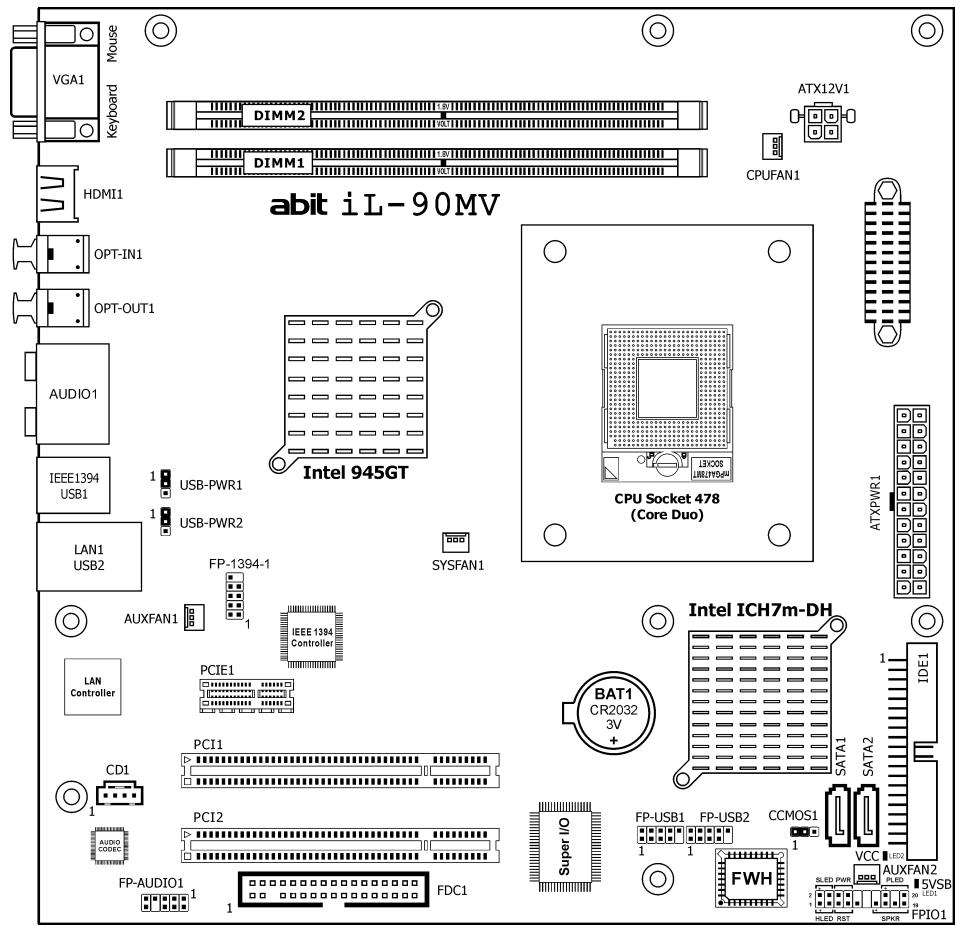
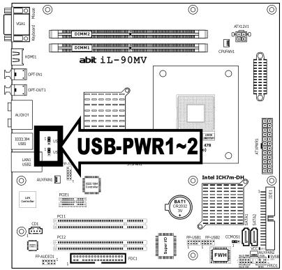
1.2 Motherboard Layout 1-3
2. Hardware Setup 2-1
2.1 Choosing a Computer Chassis 2-1
2.2 Installing Motherboard 2-1
2.3 Checking Jumper Settings 2-2
2.3.1 CMOS Memory Clearing Header and Backup Battery 2-3
2.3.2 Wake-up Headers.. 2-5
2.4 Connecting Chassis Components 2-6
2.4.1 ATX Power Connectors 2-6
2.4.2 Front Panel Switches & Indicators Headers 2-7
2.4.3 FAN Power Connectors 2-8
2.5 Installing Hardware 2-9
2.5.1 CPU Socket 478 (Core Duo) 2-9
2.5.2 DDR2 Memory Slots 2-12
2.6 Connecting Peripheral Devices 2-13
2.6.1 Floppy and IDE Disk Drive Connectors 2-13
2.6.2 Serial ATA Connectors 2-14
2.6.3 Additional USB 2.0 Port Headers.. 2-15
2.6.4 Additional IEEE1394 Port Header 2-15
2.6.5 Internal Audio Connectors 2-16
2.6.6 Front Panel Audio Connection Header 2-16
2.6.7 PCI Express X1 Add-on Slot 2-18
2.6.8 PCI Add-on Slots 2-18
2.7 Onboard Status Display 2-19
2.7.1 Power Source Indicators 2-19
2.8 Connecting Rear I/O Devices 2-20
3. BIOS Setup 3-1
3.1 Standard CMOS Features 3-2
3.2 Advanced BIOS Features 3-6
3.3 Advanced Chipset Features 3-9
3.4 Integrated Peripherals 3-12
3.5 Power Management Setup 3-17
3.6 PnP/PCI Configurations 3-20
3.7 PC Health Status.. 3-22
3.8 Load Fail-Safe Defaults 3-24
3.9 Load Optimized Defaults 3-24
3.10 Set Password 3-24
3.11 Save & Exit Setup 3-24
3.12 Exit Without Saving 3-24
4. Driver & Utility CD 4-1
4.1 Intel Chipset Software Installation Utility 4-2
4.2 Intel Matrix Storage Technology Driver 4-3
4.3 Intel Graphics Media Accelerator Driver 4-4
4.3.1 Tips on HDMI application 4-5
4.4 Realtek Audio Driver 4-8
4.5 Intel PRO Network Connections Driver 4-9
4.6 USB 2.0 Driver 4-9
4.7 Intel SATA Driver Disk Maker 4-10
4.8 ABIT EQ (The Hardware Doctor Utility) 4-11
4.9 FlashMenu (BIOS Update Utility) 4-13
5. Appendix 5-1
5.1 Troubleshooting (How to Get Technical Support?) 5-1
5.1.1 Q & A 5-1
5.1.2 Technical Support Form 5-4
5.1.3 Universal ABIT Contact Information 5-5
1. Introduction
1.1 Features & Specifications
CPU
- Designed for Intel® Core Duo/Solo, Core 2 Duo socket 478 processors with 667/533MHz FSB
Supports Enhanced Intel Speedstep® Technology (EIST)
Supports Intel® Extended Memory 64 Technology (EM64T)
Supports Intel® Execute Disable Bit capability
Chipset
Northbridge: Intel® 945GT
- Southbridge: Intel® ICH7m-DH
Memory
- Two 240-pin DIMM slots
Supports Dual Channel DDR2 667/533 Un-buffered Non-ECC memory
Supports maximum memory capacity up to 2GB
Graphics
- Integrated Intel Graphics Media Accelerator 950 Supports DirectX 9
HDMI 1.2
- Support 1080p and UXGA 1600X1200 @60MHz
Support 7.1 ch HD audio
LAN
- Onboard Intel 82573L 10/100/1000M controller
Audio
- Onboard 7.1 channels Intel High Definition Audio CODEC
Supports auto jack sensing and optical S/PDIF In/Out - Dolby Master Studio Certified
Expansion Slots
- 1x PCI-E X1 slot
- 2x PCI slots
Internal I/O Connectors
- 1x Floppy port
1x ATA 100/66/33 connector - 2x SATA 1.5Gb/s connectors
- 2x USB 2.0 headers
-
1x IEEE1394 header
-
1x FP-Audio header
- 1x CD-IN connector
Rear Panel I/O
- 1x VGA connector
- 1x PS/2 Keyboard connector
- 1x PS/2 Mouse connector
1x HDMI 1.2 connector - 1x OPT-IN1 connector
- 1x OPT-OUT1 connector
- 1x AUDIO Connector (Surround-Left / Surround-Right, Rear-Left / Rear-Right, Center/Subwoofer, Mic-In, Line-In, Line-Out)
- 1x IEEE 1394 connector
4x USB 2.0 connectors
1x RJ-45 Gigabit LAN connector
Serial ATA
Supports 2 Ports Serial ATA at 1.5Gb/s data transfer rate
Support RAID 0/1
Supports SATA AHCI, providing native command queuing and native hot plug
IEEE 1394
Supports 2 Ports IEEE 1394 at 400Mb/s data transfer rate
RoHS Compliancy
100% Lead-free process and RoHS compliancy
ABIT Engineered
- ABIT OTES STREAM Thermal Solution
Miscellaneous
- Micro ATX form factor (245mm x 245mm)
※ Specifications and information contained herein are subject to change without notice.
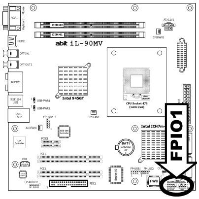
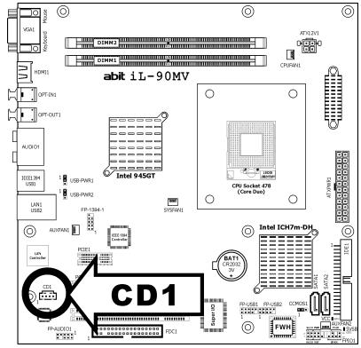
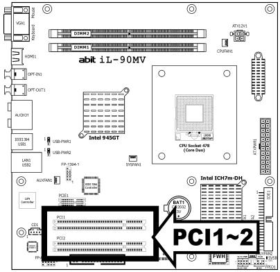
1.2 Motherboard Layout

2. Hardware Setup
In this chapter we will elaborate all the information you need upon installing this motherboard to your computer system.
Always power off the computer and unplug the AC power cord before adding or removing any peripheral or component. Failing to so may cause severe damage to your motherboard and/or peripherals. Plug in the AC power cord only after you have carefully checked everything.
2.1 Choosing a Computer Chassis
- This motherboard carries a Micro ATX form factor of 245 × 245 ~mm . Choose a chassis big enough to install this motherboard.
- As some features for this motherboard are implemented by cabling connectors on the motherboard to indicators and switches or buttons on the chassis, make sure your chassis supports all the features required.
- If there is possibility of adopting some more hard drives, make sure your chassis has sufficient power and space for them.
- Most chassis have alternatives for I/O shield located at the rear panel. Make sure the I/O shield of the chassis matches the I/O port configuration of this motherboard. You can find an I/O shield specifically designed for this motherboard in its package.
2.2 Installing Motherboard
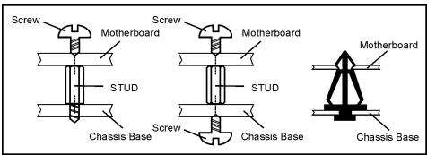
Most computer chassis have a base with many mounting holes to allow the motherboard to be securely attached, and at the same time, prevent the system from short circuits. There are two ways to attach the motherboard to the chassis base:
- with studs,
- or with spacers
In principle, the best way to attach the board is to use studs. Only if you are unable to do this should you attach the board with spacers.
Line up the holes on the board with the mounting holes on the chassis. If the holes line up and there are screw holes, you can attach the board with studs. If the holes line up and there are only slots, you can only attach with spacers. Take the tip of the spacers and insert them into the slots. After doing this to all the slots, you can slide the board into position aligned with slots. After the board has been positioned, check to make sure everything is OK before putting the chassis back on.

To install this motherboard:
- Locate all the screw holes on the motherboard and the chassis base.
- Place all the studs or spacers needed on the chassis base and have them tightened.
- Face the motherboard's I/O ports toward the chassis's rear panel.
- Line up all the motherboard's screw holes with those studs or spacers on the chassis.
- Install the motherboard with screws and have them tightened.

Face the chassis's rear panel.
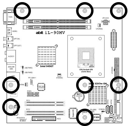
To prevent shorting the PCB circuit, please REMOVE the metal studs or spacers if they are already fastened on the chassis base and are without mounting-holes on the motherboard to align with.
2.3 Checking Jumper Settings
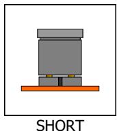
For a 2-pin jumper, plug the jumper cap on both pins will make it CLOSE (SHORT). Remove the jumper cap, or plug it on either pin (reserved for future use) will leave it at OPEN position.
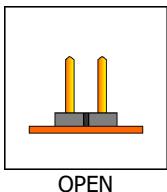
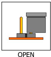
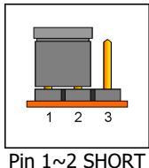
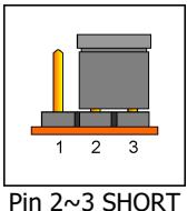
For 3-pin jumper, pin 1 2 or pin 2 3 can be shorted by plugging the jumper cap in.
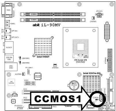
2.3.1 CMOS Memory Clearing Header and Backup Battery
The time to clear the CMOS memory occurs when (a) the CMOS data becomes corrupted, (b) you forgot the supervisor or user password preset in the BIOS menu, (c) you are unable to boot-up the system because the CPU ratio/clock was incorrectly set in the BIOS menu, or (d) whenever there is modification on the CPU or memory modules.
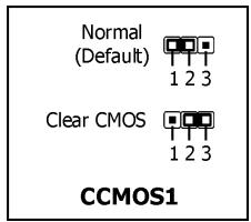
This header uses a jumper cap to clear the CMOS memory and have it reconfigured to the default values stored in BIOS.
- Pins 1 and 2 shorted (default): Normal operation.
- Pins 2 and 3 shorted: Clear CMOS memory.
To clear the CMOS memory and load in the default values:
- Power off the system and disconnect with AC power source.
- Set pin 2 and pin 3 shorted by the jumper cap. Wait for a few seconds. Set the jumper cap back to its default settings --- pin 1 and pin 2 shorted.
- Power on the system.
- For incorrect CPU ratio/clock settings in the BIOS, press
key to enter the BIOS setup menu right after powering on system. - Set the CPU operating speed back to its default or an appropriate value.
- Save and exit the BIOS setup menu.
CMOS Backup Battery:
An onboard battery saves the CMOS memory to keep the BIOS information stays on even after disconnected your system with power source. Nevertheless, this backup battery exhausts after some five years. Once the error message like "CMOS BATTERY HAS Failed" or "CMOS checksum error" displays on monitor, this backup battery is no longer functional and has to be renewed.
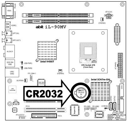
To renew the backup battery:
- Power off the system and disconnect with AC power source.
- Remove the exhausted battery.
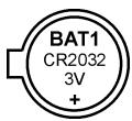
- Insert a new CR2032 or equivalent battery. Pay attention to its polarity. The "+" side is its positive polarity.
- Connect AC power source and power on the system.
- Enter the BIOS setup menu. Reconfigure the setup parameters if necessary.
CAUTION:
Danger of explosion may arise if the battery is incorrectly renewed.
※ Renew only with the same or equivalent type recommended by the battery manufacturer.
※ Dispose of used batteries according to the battery manufacturer's instructions.
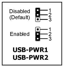
2.3.2 Wake-up Headers
These headers use a jumper cap to enable/disable the wake-up function.
USB-PWR1:
Pin 1-2 shorted (default): Disable wake-up function support at USB1 port.
Pin 2-3 shorted: Enable wake-up function support at USB1 port.
USB-PWR2:
Pin 1-2 shorted (default): Disable wake-up function support at USB2 port.
Pin 2-3 shorted: Enable wake-up function support at USB2 port
2.4 Connecting Chassis Components
2.4.1 ATX Power Connectors
These connectors provide the connection from an ATX power supply. As the plugs from the power supply fit in only one orientation, find the correct one and push firmly down into these connectors.
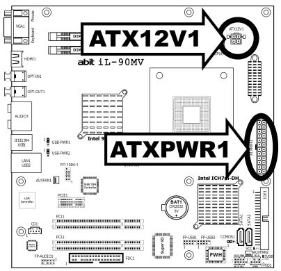
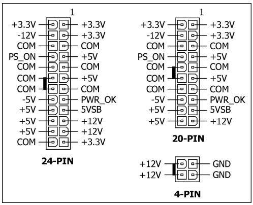
ATX 24-Pin Power Connector:
The power supply with 20-pin or 24-pin cables can both be connected to this 24-pin connector. Connect from pin-1 for either type. However, a 20-pin power supply may cause the system unstable or even unbootable for the sake of insufficient electricity. A minimum power of 300W or higher is recommended.
ATX 12V 4-Pin Power Connector:
This connector supplies power to CPU. The system will not start without connecting power to this one.
2.4.2 Front Panel Switches & Indicators Headers
This header is used for connecting switches and LED indicators on the chassis front panel.
Watch the power LED pin position and orientation. The mark "+" align to the pin in the figure below stands for positive polarity for the LED connection. Please pay attention to connect these headers. A wrong orientation will only cause the LED not lighting, but a wrong connection of the switches could cause system malfunction.
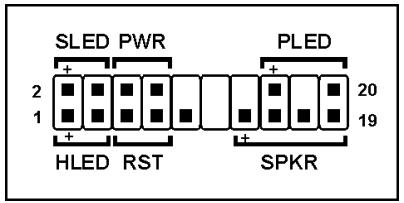
HLED (Pin 1, 3):
Connects to the HDD LED cable of chassis front panel.
RST (Pin 5, 7):
Connects to the Reset Switch cable of chassis front panel.
SPKR (Pin 13, 15, 17, 19):
Connects to the System Speaker cable of chassis.
- SLED (Pin 2_r4 ):
Connects to the Suspend LED cable (if there is one) of chassis front panel.
PWR (Pin 6, 8):
Connects to the Power Switch cable of chassis front panel.
- PLED (Pin 16, 18, 20):
Connects to the Power LED cable of chassis front panel.
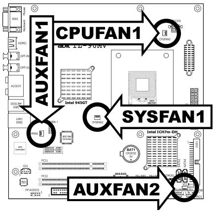
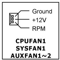
2.4.3 FAN Power Connectors
These connectors each provide power to the cooling fans installed in your system.
- CPUFAN1: CPU Fan Power Connector
- SYSFAN1: System Fan Power Connector
- AUXFAN1~2: Auxiliary Fan Power Connector
These fan connectors are not jumpers. DO NOT place jumper caps on these connectors.
2.5 Installing Hardware
DO NOT scratch the motherboard when installing hardware. An accidentally scratch of a tiny surface-mount component may seriously damage the motherboard.
2.5.1 CPU Socket 478 (Core Duo)
※ Be cautious when installing CPU into this socket. Prevent the contact pins of the socket and the CPU from breaking or bending.
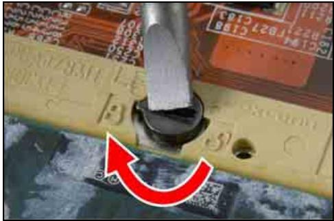
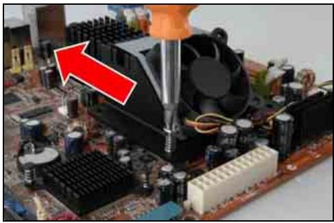
- Use a flat-head screwdriver to turn the screw bolt counter clockwise to unlock position.

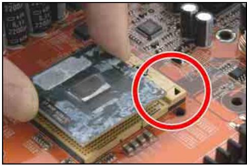
- Carefully hold the CPU by both of its edges above the CPU socket. Align the gold-triangle mark with the Pin-1 of CPU socket. Place the CPU vertically and easily down into the socket.
Do not force the CPU in; it only fits in one orientation.
- Use a flat-head screw driver to turn the screw bolt clockwise from its unlock position to the lock position.
- Peel off the protective film from the retention module. This will expose the adhesive sponge.
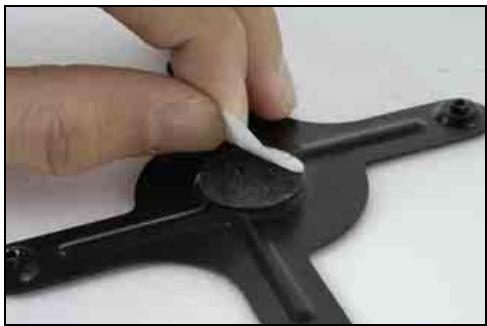
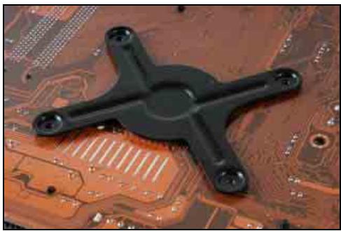
- Face the retention module with the side of adhesive sponge toward the bottom side of the motherboard. Align the four screw holes from the retention module through the motherboard.
- Peel off the protecting film that was originally attached to the bottom of CPU heatsink. This film prevents the thermal paste from being touched by anything but the CPU die, and so it has to be removed to increase the contact with the CPU die after having installed the heatsink.
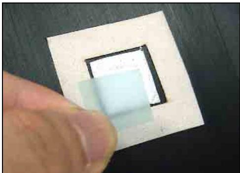
Forgetting to do so may cause the CPU over-heated and eventually ruined!
Watch out for the integrity and usability of the thermal paste each time when re-installing the heatsink. Applying a few drop of thermal paste will help to increase the contact in between the CPU die and heatsink, especially when having installed and removed the heatsink for several times.
- Carefully place the heatsink onto CPU socket in the direction of blowing its airflow toward rear panel.
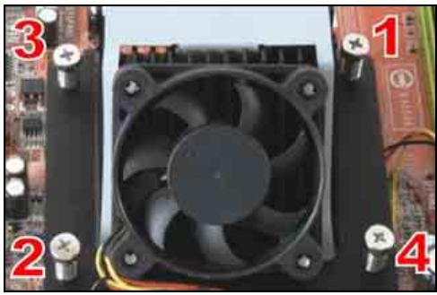
Use a cross-head screw driver to lock the four screws around the heatsink.
- Lock the screws diagonally in the order of (1) (2) (3) (4)
Turn the screw halfway down the screw hole. Do not over-tighten the screw all the way down into the screw hole one at a time. Avoid CPU damage caused by unbalanced forcing.
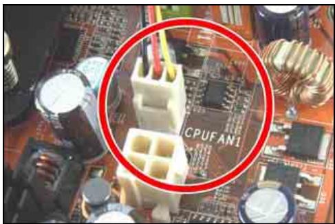
- Plug the fan power connector from the CPU cooler to the "CPUFAN1" connector on this motherboard.
Now complete the CPU and heatsink installation.
※ The installation procedures vary with different types of CPU fan-and-heatsink assembly. The one shown here is served for DEMO only. For detailed information on how to install the one you bought, refer to its installation guidelines.
A higher fan speed will be helpful for better airflow and heat-dissipation. Nevertheless, stay alert to touch any heatsink since the high temperature generated by the working system is still possible.
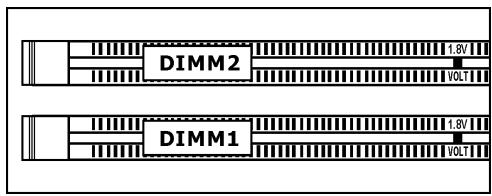
2.5.2 DDR2 Memory Slots
This motherboard provides two 240-pin DIMM slots for Dual Channel DDR2 667/533 memory modules with memory expansion size up to 2GB.
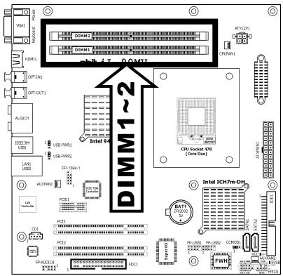
To reach the optimum performance in dual-channel configurations, install DDR DIMM pairs at the same density, DRAM technology and bus width for both slots.
To install system memory:
- Power off the computer and unplug the AC power cord before installing or removing memory modules.
- Locate the DIMM slot on the board.
- Hold two edges of the DIMM module carefully, keep away of touching its connectors.
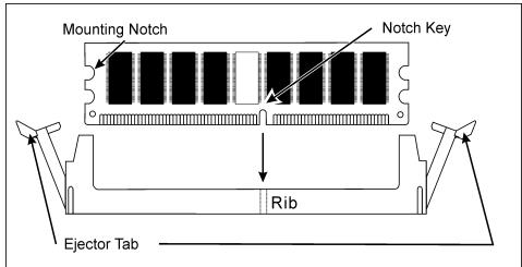
- Align the notch key on the module with the rib on the slot.
- Firmly press the module into the slots until the ejector tabs at both sides of the slot automatically snaps into the mounting notch. Do not force the DIMM module in with extra force as the DIMM module only fit in one direction.
- To remove the DIMM modules, push the two ejector tabs on the slot outward simultaneously, and then pull out the DIMM module.
- Static electricity can damage the electronic components of the computer or optional boards. Before starting these procedures, ensure that you are discharged of static electricity by touching a grounded metal object briefly.
2.6 Connecting Peripheral Devices
2.6.1 Floppy and IDE Disk Drive Connectors
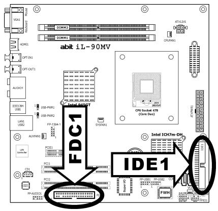
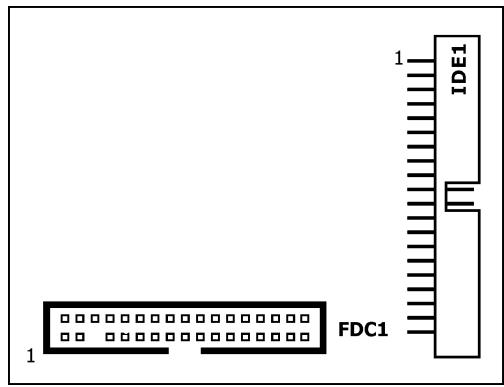
The FDC1 connector connects up to two floppy drives with a 34-wire, 2-connector floppy cable. Connect the single end at the longer length of ribbon cable to the FDC1 on the board, the two connectors on the other end to the floppy disk drives connector. Generally you need only one floppy disk drive in your system.
The red line on the ribbon cable must be aligned with pin-1 on both the FDC1 port and the floppy connector.
Each of the IDE port connects up to two IDE drives at Ultra ATA/100 mode by one 40-pin, 80-conductor, and 3-connector Ultra ATA/66 ribbon cables.
Connect the single end (blue connector) at the longer length of ribbon cable to the IDE port of this board, the other two ends (gray and black connector) at the shorter length of the ribbon cable to the connectors of your hard drives.
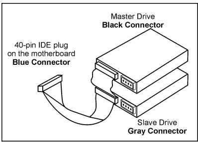
※ Make sure to configure the "Master" and "Slave" relation before connecting two drives by one single ribbon cable. The red line on the ribbon cable must be aligned with pin-1 on both the IDE port and the hard-drive connector.
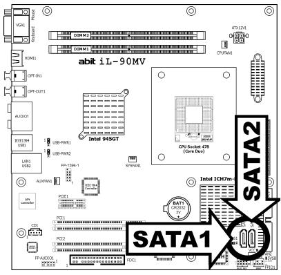
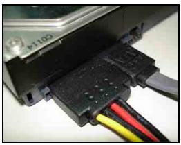
2.6.2 Serial ATA Connectors
Each SATA connector serves as one single channel to connect one SATA device by a thin SATA cable.
For more information on how to configure the function mode for SATA, please refer to the item "On-Chip SATA Controller" in the BIOS menu of "On-Chip IDE Device".

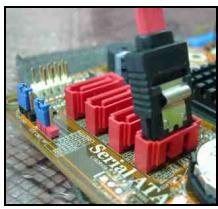
To connect SATA device:
- Attach either end of the signal cable to the SATA connector on motherboard. Attach the other end to SATA device.
- Attach the SATA power cable to the SATA device and connect the other end from the power supply.
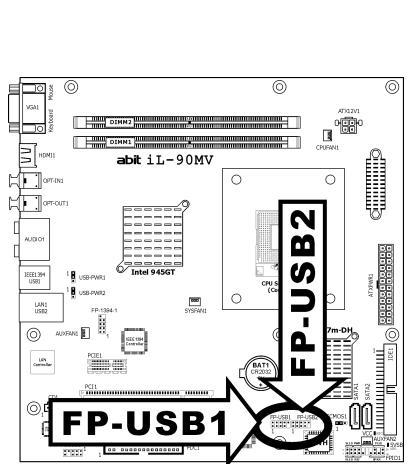
2.6.3 Additional USB 2.0 Port Headers
Each header supports 2x additional USB 2.0 ports by connecting bracket or cable to the rear I/O panel or the front-mounted USB ports of your chassis.
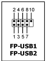
| Pin | Pin Assignment | Pin | Pin Assignment |
| 1 | VCC | 2 | VCC |
| 3 | Data0 - | 4 | Data1 - |
| 5 | Data0 + | 6 | Data1 + |
| 7 | Ground | 8 | Ground |
| 10 | NC |
※ Make sure the connecting cable bears the same pin assignment.
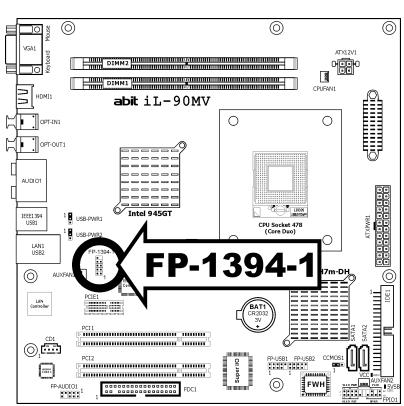
2.6.4 Additional IEEE1394 Port Header
Each header supports 1x additional IEEE1394 port by connecting bracket or cable to the rear I/O panel or the front-mounted IEEE1394 port of your chassis.
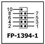
| Pin | Pin Assignment | Pin | Pin Assignment |
| 1 | TPA0 + | 2 | TPA0 - |
| 3 | Ground | 4 | Ground |
| 5 | TPB0 + | 6 | TPB0 - |
| 7 | +12V | 8 | +12V |
| 10 | Ground |
※ Make sure the connecting cable bears the same pin assignment.
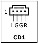
2.6.5 Internal Audio Connectors
This connector connects to the audio output of internal CD-ROM drive or add-on card.
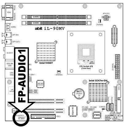
2.6.6 Front Panel Audio Connection Header
This header provides the front panel connection for HD (High Definition) Audio, yet for AC'97 Audio CODEC connection, you must carefully check the pin assignment before connecting from the front panel module. An incorrect connection may cause malfunction or even damage the motherboard.
※ Please do not connect the "Ground" cable or "USB VCC" cable from the front panel module to the Pin 4 "AVCC" of this header.
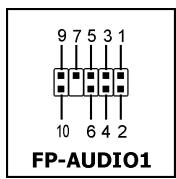
| Pin | Pin Assignment (HD AUDIO) |
| 1 | MIC2 L |
| 2 | AGND |
| 3 | MIC2 R |
| 4 | AVCC |
| 5 | FRO-R |
| 6 | MIC2_JD |
| 7 | F_IO_SEN |
| 9 | FRO-L |
| 10 | LINE2_JD |
| Pin | Pin Assignment (AC'97 AUDIO) |
| 1 | MIC In |
| 2 | GND |
| 3 | MIC Power |
| 4 | NC |
| 5 | Line Out (R) |
| 6 | NC |
| 7 | NC |
| 9 | Line Out (L) |
| 10 | NC |
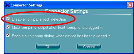
Driver Configuration for AC'97 audio connection:
The audio driver is originally configured to support HD Audio. For AC'97 audio connection, you may:
- Right-click the "Realtek HD Audio Manager" icon in system tray.

- Click "Audio I/O" tab, and then click "Connector Settings".
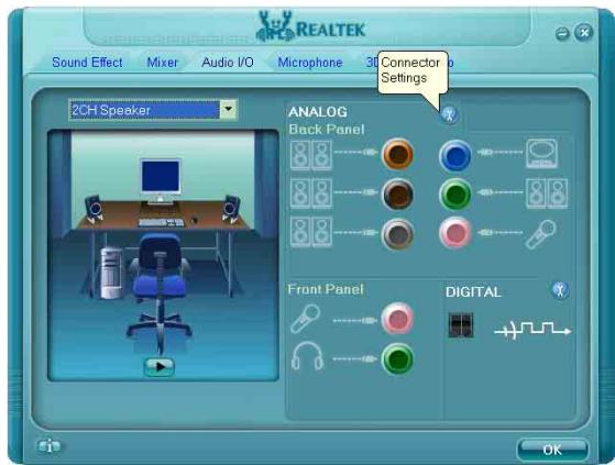
- Click "Disabled front panel jack detection", and then click "OK" to confirm.
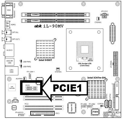
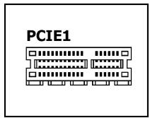
2.6.7 PCI Express X1 Add-on Slot
This slot provides the connection of add-on cards that comply with PCI Express specifications.
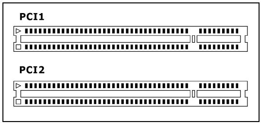
2.6.8 PCI Add-on Slots
These slots provide the connection of add-on cards that comply with PCI specifications.
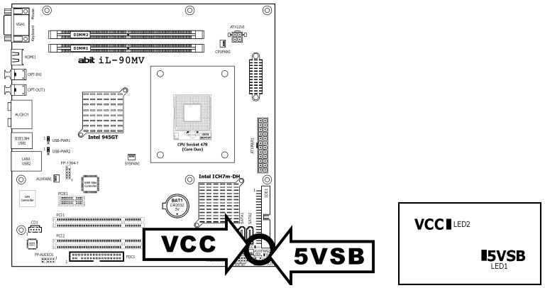
2.7 Onboard Status Display
2.7.1 Power Source Indicators
These indicators work as a reminding device to display the power status of this motherboard with power source connected.
- 5VSB: This LED lights up when the power supply is connected with power source.
VCC: This LED lights up when the system power is on.
2.8 Connecting Rear I/O Devices
The rear I/O part of this motherboard provides the following I/O ports:
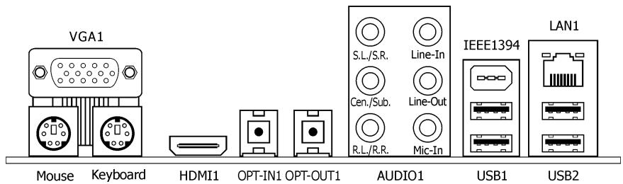
VGA1: Connects to monitor input.
- Mouse: Connects to PS/2 mouse.
- Keyboard: Connects to PS/2 keyboard.
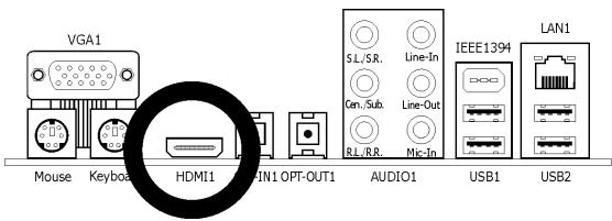
- HDMI1: Connects to multimedia devices of HDMI protocol.
Connect your HDMI device from this connector only with an HDMI-to-HDMI cable. DO NOT connect with an HDMI-to-DVI cable.
For more information on HDMI configuration, refer to the BIOS Setup Menu in "Advanced Chipset Features" and the "Tips on HDMI application" in the chapter of "Intel Graphics Media Accelerator Driver" installation.
- OPT-IN1: This connector provides an S/PDIF-In connection through optical fiber to digital multimedia devices.
- OPT-OUT1: This connector provides an S/PDIF-Out connection through optical fiber to digital multimedia devices.
AUDIO1:
S.L./S.R. (Surround Left / Surround Right): Connects to the surround left and surround right channel in the 7.1 channel audio system.
Cen./Sub. (Center / Subwoofer): Connects to the center and subwoofer channel in the 7.1 channel audio system.
R.L./R.R. (Rear Left / Rear Right): Connects to the rear left and rear right channel in the 7.1 channel audio system.
Line-In: Connects to the line out from external audio sources.
Line-Out: Connects to the front left and front right channel in the 7.1-channel or regular 2-channel audio system.
Mic-In: Connects to the plug from external microphone.
- IEEE1394: Connects to devices of IEEE1394 protocol
LAN1: Connects to Local Area Network. - USB1/USB2: Connects to USB devices such as scanner, digital speakers, monitor, mouse, keyboard, hub, digital camera, joystick etc.
3. BIOS Setup
This motherboard provides a programmable EEPROM that you can update the BIOS utility. The BIOS (Basic Input/Output System) is a program that deals with the basic level of communication between processor and peripherals. Use the BIOS Setup program only when installing motherboard, reconfiguring system, or prompted to "Run Setup". This chapter explains the Setup Utility of BIOS utility.
After powering up the system, the BIOS message appears on the screen, the memory count begins, and then the following message appears on the screen:
PRESS DEL TO ENTER SETUP
If this message disappears before you respond, restart the system by pressing <Ctrl> + <Alt> + <Del> keys, or by pressing the Reset button on computer chassis. Only when it failed by these two methods can you restart the system by powering it off and then back on.
After pressing <Del> key, the main menu screen appears.
| Phoenix - AwardBIOS CMOS Setup Utility | |
| Standard CMOS Features | PC Health Status |
| Advanced BIOS Features | Load Fail-Safe Defaults |
| Advanced Chipset Features | Load Optimized Defaults |
| Integrated Peripherals | Set Password |
| Power Management Setup | Save & Exit Setup |
| PnP/PCI Configurations | Exit Without Saving |
| Esc: Quit | ↑↓→← : Select Item |
| F10: Save & Exit Setup | (945GT-W627EHG-6A79KA1AC-00) |
| Time, Date, Hard Disk Type... | |
In order to increase system stability and performance, our engineering staff is constantly improving the BIOS menu. The BIOS setup screens and descriptions illustrated in this manual are for your reference only, and may not completely match with what you see on your screen.
3.1 Standard CMOS Features
| Phoenix - AwardBIOS CMOS Setup Utility Standard CMOS Features | ||
| Date (mm:dd:yy) | Tue. Aug 1 2006 | Item Help |
| Time (hh:mm:ss) | 12 : 34 : 56 | |
| IDE Channel 1 Master | None | |
| IDE Channel 1 Slave | None | |
| IDE Channel 2 Master | None | |
| IDE Channel 2 Slave | None | |
| IDE Channel 3 Master | None | |
| IDE Channel 3 Slave | None | |
| IDE Channel 4 Master | None | |
| IDE Channel 4 Slave | None | |
| Drive A | 1.44M, 3.5 in. | |
| Drive B | None | |
| Floppy 3 Mode Support | Disabled | |
| Halt On | All, But keyboard | |
| Base Memory | 640K | |
| Extended Memory | 1047552K | |
| Total Memory | 1047552K | |
| ↑↓→←:Move Enter:Select +/-/PU/PD:Value F10:Save ESC:Exit F1:General Help F5: Previous Values F6: Fail-Safe Defaults F7: Optimized Defaults | ||
Date (mm:dd:yy)
This item sets the date you specify (usually the current date) in the format of [Month], [Date], and [Year].
Time (hh:mm:ss)
This item sets the time you specify (usually the current time) in the format of [Hour], [Minute], and [Second].

IDE Channel 1 Master/Slave, IDE Channel 2 Master/Slave, IDE Channel 3 Master/Slave, IDE Channel 4 Master/Slave
Click
| Phoenix - AwardBIOS CMOS Setup Utility IDE Channel 1 Master | ||
| IDE HDD Auto-Detection | Press Enter | Item Help |
| IDE Channel 1 Master | Auto | |
| Access Mode | Auto | |
| Capacity | 0 MB | |
| Cylinder | 0 | |
| Head | 0 | |
| Precomp | 0 | |
| Landing Zone | 0 | |
| Sector | 0 | |
| ↑↓→←:Move Enter:Select +/-/PU/PD:Value F10:Save ESC:Exit F1:General Help F5: Previous Values F6: Fail-Safe Defaults F7: Optimized Defaults | ||
※ The items "IDE Channel 3 Master/Slave" and "IDE Channel 4 Master/Slave" appear only when the item "On-Chip SATA Controller" in the "On-Chip IDE Device" menu is set to [Enhanced Mode].
IDE HDD Auto-Detection
This item allows you to detect the parameters of IDE drives by pressing
IDE Channel 1 Master/Slave, IDE Channel 2 Master/Slave, Extended IDE Drive
When set to [Auto], the BIOS will automatically check what kind of IDE drive you are using. If you want to define your own drive by yourself, set it to [Manual] and make sure you fully understand the meaning of the parameters. Please refer to the instruction manual provided by the device's manufacturer to get the setting right.
Access Mode
This item selects the mode to access your IDE devices. Leave this item to its default [Auto] setting to detect the access mode of your HDD automatically.
Capacity
This item displays the approximate capacity of the disk drive. Usually the size is slightly greater than the size of a formatted disk given by a disk-checking program.
| Cylinder This item configures the numbers of cylinders. |
| Head This item configures the numbers of read/write heads. |
| Precomp This item displays the number of cylinders at which to change the write timing. |
| Landing Zone This item displays the number of cylinders specified as the landing zone for the read/write heads. |
| Sector This item configures the numbers of sectors per track. Back to Standard CMOS Features Setup Menu |
| Drive A & Drive B This item sets the type of floppy drives (usually only Drive A) installed. |
| Floppy 3 Mode Support This item allows you to use "3 Mode Floppy Drive" in Japanese computer systems by selecting drive A, B, or both. Leave this item to its default [Disabled] setting if you are not using this Japanese standard floppy drive. |
| Halt On This item determines whether the system stops if an error is detected during system boot-up. [All Errors]: The system-boot will stop whenever the BIOS detect a non-fatal error. [No Errors]: The system-boot will not stop for any error detected. [All, But Keyboard]: The system-boot will stop for all errors except a keyboard error. [All, But Diskette]: The system-boot will stop for all errors except a diskette error. [All, But Disk/Key]: The system-boot will stop for all errors except a diskette or keyboard error. |
| Base Memory This item displays the amount of base memory installed in the system. The value of the base memory is typically 640K for system with 640K or more memory size installed on the motherboard. |
| Extended Memory This item displays the amount of extended memory detected during system boot-up. |
Total Memory
This item displays the total memory available in the system.
3.2 Advanced BIOS Features
Phoenix - AwardBIOS CMOS Setup Utility Advanced BIOS Features
| Quick Power on Self Test | Enabled | Item Help |
| CPU Feature | Press Enter | |
| Hard Disk Boot Priority | Press Enter | |
| First Boot Device | Floppy | |
| Second Boot Device | Hard Disk | |
| Third Boot Device | IDE CDROM | |
| Boot Other Device | Enabled | |
| Boot Up Floppy Seek | Disabled | |
| Boot Up NumLock Status | On | |
| Security Option | Setup | |
| MPS Version Ctrl For OS | 1.4 | |
| Delay IDE Initial (Secs) | 0 | |
| Full Screen Logo Show | Enabled | |
| Disable Unused PCI Clock | Yes |
:Move Enter:Select + / - / PU/PD:Value F10:Save ESC:Exit F1:General Help F5:Previous Values F6:Fail-Safe Defaults F7:Optimized Defaults
Quick Power On Self Test
When set to [Enabled], this item speeds up the Power On Self Test (POST) after powering on the system. The BIOS shorten or skip some check during the POST.

CPU Feature
Click
| Phoenix - AwardBIOS CMOS Setup Utility Advanced BIOS Features | |
| C1E Function Enabled | Item Help |
| Execute Disable Bit Enabled | |
| EIST Function Enabled | |
:Move Enter:Select + / - / PU/PD:Value F10:Save ESC:Exit F1:General Help F5:Previous Values F6:Fail-Safe Defaults F7:Optimized Defaults
C1E Function
This item appears only for certain processors with the C1E (Enhanced Halt State) Function. When set to [Enabled], the processor will further reduce the total power consumption.
Execute Disable Bit
This item appears only for certain processors with the Execute Disable Bit (XD bit) feature. When set to [Enabled], this item allows the processor to prevent data pages from being used by malicious software to execute code and provide memory protection.
EIST Function
This item appears only for certain processors with the EIST (Enhanced Intel SpeedStep Technology) Function. When set to [Enabled], EIST will dynamically switch between multiple frequency and voltage points to optimize the power and performance balance of the processor and system based on demand.

Back to Advanced BIOS Features Setup Menu
Hard Disk Boot Priority
This item selects the hard disks booting priority. By pressing
This item functions only when there is the option of [Hard Disk] in any one of the First/Second/Third Boot Device items.
First Boot Device / Second Boot Device / Third Boot Device / Boot Other Device
Select the drive to boot first, second and third in the [First Boot Device], [Second Boot Device], and [Third Boot Device] items respectively. The BIOS will boot the operating system according to the sequence of the drive selected. Set [Boot Other Device] to [Enabled] if you wish to boot from another device other than these three items.
Boot Up Floppy Seek
When set to [Enabled], the BIOS will check whether the floppy disk drive is installed or not.
Boot Up NumLock Status
This item determines the default state of the numeric keypad at system booting up.
[On]: The numeric keypad functions as number keys.
[Off]: The numeric keypad functions as arrow keys.
Security Option
This item determines when the system will prompt for password - every time the system boots or only when enters the BIOS setup.
[Setup]: The password is required only when accessing the BIOS Setup.
[System]: The password is required each time the computer boots up.
Don't forget your password. If you forget the password, you will have to open the computer case and clear all information in the CMOS before you can start up the system. But by doing this, you will have to reset all previously set options.
MPS Version Ctrl For OS
This item specifies which version of MPS (Multi-Processor Specification) this motherboard will use. Leave this item to its default setting.
Delay IDE Initial (Secs)
This item allows the BIOS to support some old or special IDE devices by prolonging this delay time. A larger value will give more delay time to the device for which to initialize and to prepare for activation.
Full Screen LOGO Show
This item determines to show the full screen logo when booting.
Disable Unused PCI Clock
This option disables the clock of PCI slot that is not in use.
[Yes]: The system automatically detect the unused DIMM and PCI slots, and stop sending clock signal to these unused PCI slots.
[No]: The system always send clock signal to all PCI slots.
※ Set this option to [No] setting if there are adapters that cannot be automatically detected by the system and will cause malfunction.
3.3 Advanced Chipset Features
Phoenix - AwardBIOS CMOS Setup Utility Advanced Chipset Features
| DRAM Timing Selectable | By SPD | Item Help |
| X - CAS Latency Time (tCL) | Auto | |
| X - RAS# to CAS# Delay (tRCD) | Auto | |
| X - RAS# Precharge (tRP) | Auto | |
| X - Precharge Delay (tRAS) | Auto | |
| X - System Memory Frequency | Auto | |
| PCI Express Root Port Func | Press Enter | |
| Init Display First | PCI Slot | |
| HDMI Port Display | DVI | |
| ** VGA Setting ** | ||
| Frame Buffer Size | 8MB | |
| DVMT Mode | DVMT | |
| DVMT/FIXED Memory Size | 128MB |
:Move Enter:Select + / - / PU/PD:Value F10:Save ESC:Exit F1:General Help F5:Previous Values F6:Fail-Safe Defaults F7:Optimized Defaults
DRAM Timing Selectable
This item sets the optimal timings for the following four items, depending on the memory module you are using. The default setting "By SPD" configures these four items by reading the contents in the SPD (Serial Presence Detect) device. The EEPROM on the memory module stores critical parameter information about the module, such as memory type, size, speed, voltage interface, and module banks.
CAS Latency Time (tCL)
This item controls the latency between the DRAM read command and the time that the data becomes actually available.
RAS# to CAS# Delay (tRCD)
This item controls the latency between the DRAM active command and the read/write command.
RAS# Precharge (tRP)
This item controls the idle clocks after issuing a precharge command to the DRAM.
Precharge Delay (tRAS)
This item controls the number of DRAM clocks used for the DRAM parameters.
System Memory Frequency
This item selects the DRAM speed.

PCI Express Root Port Func
Click
| Phoenix - AwardBIOS CMOS Setup Utility PCI Express Root Port Func | ||
| PCI Express Slot 1 | Auto | Item Help |
| PCIe Compliance Mode | v1.0a | |
| ↑↓→←:Move Enter:Select +/-/PU/PD:Value F10:Save ESC:Exit F1:General Help F5:Previous Values F6:Fail-Safe Defaults F7:Optimized Defaults | ||
PCI Express Slot 1
This option enables or disables the PCI Express port function.
PCIe Compliancy Mode
This item selects the mode for PCI Express add-on card.

Back to Advanced Chipset Features Setup Menu
Init Display First
This item selects the primary boot device.
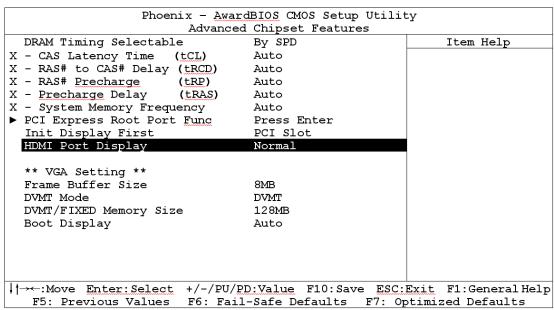
HDMI Port Display
This item selects the type of display device connected through the "HDMI Port" on this motherboard.
[DVI]: Select this option if you are connecting a non-HDMI monitor through the "HDMI Port" on this motherboard. This is the default setting.
[Normal]: Select this option if you are connecting HDMI digital display through the "HDMI Port" on this motherboard.
An unmatched configuration will cause the display device abnormal. For example, an HDMI digital device connected to "HDMI Port" under the [DVI] selection will have no sound on the digital display, whereas a non-HDMI monitor connected to "HDMI Port" under the [Normal] selection will cause the screen flickering. Select the correct one for your display device.
Frame Buffer Size
This item selects the size of memory pre-allocated for frame buffer.
DVMT Mode
This item selects the mode of graphics memory that the system will support.
DVMT/FIXED Memory Size
This item selects the size of graphics memory that the system will support.
3.4 Integrated Peripherals
Phoenix - AwardBIOS CMOS Setup Utility Integrated Peripherals
On-Chip IDE Device
On-Chip PCI Device
Super-I0 Device
Onboard PCI Device
Press Enter
Press Enter
Press Enter
Press Enter
Item Help
:Move Enter:Select + / - / PU/PD:Value F10:Save ESC:Exit F1:General Help F5:Previous Values F6:Fail-Safe Defaults F7:Optimized Defaults

On-Chip IDE Device
Click
Phoenix - AwardBIOS CMOS Setup Utility On-Chip IDE Device
IDE Bus Master Enabled On-Chip IDE-1 Controller Enabled
*** On-Chip Serial ATA Setting ***
X On-Chip SATA Mode IDE
X - SATA RAID ROM Enabled
On-Chip SATA Controller Auto
X-PATA IDE Mode IDE-1
*** IDE Channel Configuration ***
IDE Channel 1 Master Auto
IDE Channel 1 Slave Auto
IDE Channel 2 Master Auto
IDE Channel 2 Slave Auto
IDE Channel 3 Master Auto
IDE Channel 3 Slave Auto
IDE Channel 4 Master Auto
IDE Channel 4 Slave Auto
:Move Enter:Select + / - / PU/PD:Value F10:Save ESC:Exit F1:General Help F5:Previous Values F6:Fail-Safe Defaults F7:Optimized Defaults
Item Help
IDE Bus Master
This option enables or disables the IDE bus mastering capability under the DOS environment.
On-Chip IDE-1 Controller
This item selects whether to enable or disable the IDE-1 controller.
On-Chip SATA Mode
This item determines the mode for on-chip Serial ATA.
[IDE]: The on-chip Serial ATA served as IDE mode.
[RAID]: The on-chip Serial ATA served as RAID mode.
[AHCI]: The on-chip Serial ATA served as AHCI (Advanced Host Controller Interface) mode for advanced performance and usability.
※ In the "Intel Matrix Storage Manager Option ROM" utility for the [RAID] mode configuration, the physical disk "Port " indicates connector "SATA1", whereas "Port 2" indicates connector "SATA2".
※ The [RAID] option is only available when the item "On-Chip SATA Controller" is set to [Enhanced Mode].
- SATA RAID ROM
This item allows you to use the boot ROM of on-chip Serial ATA RAID to boot up system.
On-Chip SATA Controller
This item determines the function for on-chip Serial ATA.
[Disabled]: Disable the Serial ATA controller.
[Auto]: Allows the Serial ATA controller to be arranged by BIOS automatically.
[Combined Mode]: Parallel ATA and Serial ATA are combined together. Supports up to 4 IDE drives.
[Enhanced Mode]: Enable both Parallel ATA and Serial ATA. Supports up to 4 IDE drives.
[SATA Only]: The SATA is operating in legacy mode.
※ This option is configurable only when the item [On-Chip SATA Mode] is set to [IDE].
| Mode | IDE Channel 1 Master | IDE Channel 1 Slave | IDE Channel 2 Master | IDE Channel 2 Slave | IDE Channel 3 Master | IDE Channel 3 Slave |
| Enhanced | IDE Master | IDE Slave | None | None | SATA1 | SATA2 |
| Combined *1 | IDE Master | IDE Slave | None | None | None | None |
| Combined *2 | SATA1 | SATA2 | IDE Master | IDE Slave | None | None |
| SATA Only | SATA1 | SATA2 | None | None | None | None |
1: When [PATA IDE Mode] functions as IDE-1.
2: When [PATA IDE Mode] functions as IDE-2.
※ The option [Enhanced Mode] does not support the Windows 98/ME operating system.
- PATA IDE Mode
This item determines the function mode for "IDE1"connector.
[IDE-1]: "IDE1" connector served as [Primary Master] and [Primary Slave] channel. The remaining "SATA1" and "SATA2" connectors are disabled.
[IDE-2]: "IDE1" connector served as [Secondary Master] and [Secondary Slave] channel. "SATA1" and "SATA2" connector served as [Primary Master] and [Primary Slave] channel.
Refer to the following table for the relationships between IDE and SATA ports.
| PATA IDE Mode | IDE Channel 1 Master | IDE Channel 1 Slave | IDE Channel 2 Master | IDE Channel 2 Slave |
| IDE-1 | IDE Master | IDE Slave | None | None |
| IDE-2 | SATA1 | SATA2 | IDE Master | IDE Slave |
※ This option is configurable only when the item [On-Chip SATA Controller] is set to [Combined Mode].
On-Chip PCI Device
Click
| Phoenix - AwardBIOS CMOS Setup Utility On-Chip PCI Device | ||
| On-Chip USB Controller | Enabled | Item Help |
| - USB 2.0 Controller | Enabled | |
| - USB Keyboard Support via | OS | |
| - USB Mouse Support via | OS | |
| On-Chip Audio Controller | Enabled | |
| ↑↓→←:Move Enter:Select +/-/PU/PD:Value F10:Save ESC:Exit F1:General Help F5:Previous Values F6:Fail-Safe Defaults F7:Optimized Defaults | ||
On-Chip USB Controller
This option enables or disables the USB controller.
USB 2.0 Controller
This option enables or disables the USB 2.0 controller.
- USB Keyboard Support via
Select [BIOS] (the default setting) for the legacy operating system (such as DOS) that does not support USB keyboard.
- USB Mouse Support via
Select [BIOS] (the default setting) for the legacy operating system (such as DOS) that does not support USB mouse.
On-Chip Audio Controller
This option enables or disables the audio controller.

Super-IO Device
Click
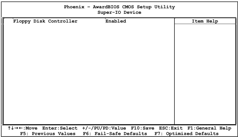
Floppy Disk Controller
This option enables or disables the floppy disk controller.

Onboard PCI Device
Click
| Phoenix - AwardBIOS CMOS Setup Utility Onboard PCI Device | ||
| IEEE 1394 Controller | Enabled | Item Help |
| Network Controller | Enabled | |
| - Invoke Boot Agent | Disabled | |
| ↑↓→←:Move Enter:Select +/-/PU/PD:Value F10:Save ESC:Exit F1:General Help F5:Previous Values F6:Fail-Safe Defaults F7:Optimized Defaults | ||
IEEE 1394 Controller
This option enables or disables the IEEE 1394 controller.
Network Controller
This option enables or disables the LAN controller.
- Invoke Boot Agent
This item allows you to use the boot ROM (instead of a disk drive) to boot up the system and access the local area network directly.
3.5 Power Management Setup
Phoenix - AwardBIOS CMOS Setup Utility
Power Management Setup
| ACPI Suspend Type | S3(Suspend To RAM) | Item Help |
| - Resume by USB From S3 | Enabled | |
| Power Button Function | Instant-Off | |
| CPU THRM-Throttling | 50.0% | |
| Wake Up by PME# of PCI | Disabled | |
| Wake Up by WAKE# of PCIe | Disabled | |
| Wake Up by Onboard LAN | Disabled | |
| Wake Up by Onboard 1394 | Disabled | |
| Wake Up by Alarm | Disabled | |
| X - Date(of month) Alarm | 0 | |
| X - Time(hh:mm:ss) Alarm | 0 : 0 : 0 | |
| Power On Function | Button Only | |
| X - KB Power On Password | Enter | |
| X - Hot Key Power On | Ctrl-F1 | |
| Restore On AC Power Loss | Power Off |
Move Enter:Select + / - / PU/PD:Value F10:Save ESC:Exit F1:General Help
F5: Previous Values F6: Fail-Safe Defaults F7: Optimized Defaults
ACPI Suspend Type
This item selects the type of Suspend mode.
[S1(PowerOn Suspend)]: Enables the Power On Suspend function.
[S3(Suspend To RAM)]: Enables the Suspend to RAM function.
-Resume by USB From S3
When set to [Enabled], this item allows you to use a USB device to wake up a system that is in the S3 (STR - Suspend To RAM) state. This item can be configured only if the item "ACPI Suspend Type" is set to [S3(STR)].
Power Button Function
This item selects the method of powering off your system:
[Delay 4 Sec.]: Pushing the power button for more than 4 seconds will power off the system. This will prevent the system from powering off in case you accidentally hit or pushed the power button.
[Instant-Off]: Pressing and then releasing the power button at once will immediately power off the system.
Wake Up by PME# of PCI
When set to [Enabled], access through the add-on PCI card can remotely wake up the system that was in Soft-Off condition. The PCI card must support the wake up function.
Wake Up by Wake# of PCIe
When set to [Enabled], access through the add-on PCI Express card can remotely wake up the system that was in Soft-Off condition. The PCI Express card must support the wake up function.
Wake Up by Onboard LAN
When set to [Enabled], access through the onboard LAN port can remotely wake up the system that was in Soft-Off condition.
Wake Up by Onboard 1394
When set to [Enabled], access through the onboard IEEE 1394 device can remotely wake up the system that was in Soft-Off condition.
Wake Up by Alarm
When set to [Enabled], you can set the date and time you would like the Soft-Off PC to power-on in the "Date (of Month) Alarm" and "Time (hh:mm:ss) Alarm" items. However, if the system is being accessed by incoming calls or the network (Resume On Ring/LAN) prior to the date and time set in these items, the system will give priority to the incoming calls or network instead.
- Date (of Month) Alarm
[0]: This option power-on the system everyday according to the time set in the "Time (hh:mm:ss) Alarm" item.
[1-31]: This option selects a date you would like the system to power-on. The system will power-on on the date set, and the time set in the "Time (hh:mm:ss) Alarm" item.
Time (hh:mm:ss) Alarm
This item sets the time you would like the system to power-on.
Power On Function
This item selects the way you want your system to power on.
[Password]: Use a password to power on the system, select this option then press
[Hot KEY]: Use any of the function keys between <F1> to <F12> to power on the system.
[Mouse Left]: Double click the mouse left button to power on the system.
[Mouse Right]: Double click the mouse right button to power on the system.
[Any KEY]: Use any keyboard keys to power on the system.
[Button Only]: Use only the power button to power on the system.
[Keyboard 98]: Use the power-on button on the "Keyboard 98" compatible keyboard to power on the system.
The mouse wake up function can only be used with the PS/2 mouse, not with the COM port or USB type. Some PS/2 mice cannot wake up the system because of compatible problems. If the specs of your keyboard are too old, it may fail to power on.
KB Power On Password
This item sets the password required in order to power on your computer.
Do not forget your password, or you will have to clear the CMOS and reset all parameters in order to utilize this function again.
Hot Key Power On
This item powers on the system by pressing
Restore On AC Power Loss
This item selects the system action after an AC power failure.
[Power Off]: When power returns after an AC power failure, the system's power remains off. You must press the Power button to power-on the system.
[Power On]: When power returns after an AC power failure, the system's power will be powered on automatically.
[Last State]: When power returns after an AC power failure, the system will return to the state where you left off before power failure occurs. If the system's power is off when AC power failure occurs, it will remain off when power returns. If the system's power is on when AC power failure occurs, the system will power-on when power returns.
3.6 PnP/PCI Configurations
| Phoenix - AwardBIOS CMOS Setup Utility PnP/PCI Configurations | ||
| Resources Controlled By Auto X - IRQ Resources Press Enter | Item Help | |
| PCI/VGA Pallete Snoop Disbaled PCI Latency Timer(CLK) 32 | ||
| ** PCI Express relative items ** | ||
| Maximum Payload Size 4096 | ||
| ↑↓→←:Move Enter:Select +/-/PU/PD:Value F10:Save ESC:Exit F1:General Help F5: Previous Values F6: Fail-Safe Defaults F7: Optimized Defaults | ||
Resources Controlled By
This item configures all of the boot and Plug-and-Play compatible devices.
[Auto]: The system will automatically detect the settings.
[Manual]: Choose the specific IRQ resources in the "IRQ Resources" menu.
IRQ Resources
Click
This item sets each system interrupt to either [PCI Device] or [Reserved].
| Phoenix - AwardBIOS CMOS Setup Utility IRQ Resources | ||
| IRQ-3 assigned to | Reserved | Item Help |
| IRQ-4 assigned to | PCI Device | |
| IRQ-5 assigned to | PCI Device | |
| IRQ-7 assigned to | PCI Device | |
| IRQ-10 assigned to | PCI Device | |
| IRQ-11 assigned to | PCI Device | |
| ↑↓→←:Move Enter:Select +/-/PU/PD:Value F10:Save ESC:Exit F1:General Help F5: Previous Values F6: Fail-Safe Defaults F7: Optimized Defaults | ||
PCI/VGA Palette Snoop
This item determines whether the MPEG ISA/VESA VGA cards can work with PCI/VGA or not.
[Enabled]: MPEG ISA/VESA VGA cards work with PCI/VGA.
[Disabled]: MPEG ISA/VESA VGA cards do not work with PCI/VGA.
PCI Latency Timer (CLK)
This item controls how long each PCI device can hold the bus before another takes over. When set to higher values, every PCI device can conduct transactions for a longer time and thus improve the effective PCI bandwidth. For better PCI performance, you should set the item to higher values.
Maximum Payload Size
This item sets the maximum TLP payload size for the PCI Express devices.
3.7 PC Health Status
Phoenix - AwardBIOS CMOS Setup Utility PC Health Status
| ▶ ABIT FanEQ Control | Press Enter | Item Help |
| FAN Fail Alarm Selectable | Disabled | |
| Shutdown When FAN Fail | Disabled | |
| CPU Shutdown Temperature | Disabled | |
| CPU Warning Temperature | 85°C/ 185°F | |
| CPU Temperature | 35°C/ 95°F | |
| System Temperature | 32°C/ 89°F | |
| PWM Temperature | 35°C/ 95°F | |
| CPU FAN Speed | 3245 RPM | |
| SYS FAN Speed | 4218 RPM | |
| AUX1 FAN Speed | 0 RPM | |
| AUX2 FAN Speed | 0 RPM | |
| CPU Core Voltage | 1.25V | |
| DDR2 Voltage | 1.88V | |
| DDR2 VTT Voltage | 0.93V | |
| PCIe Voltage | 1.75V | |
| ATX +12V | 11.98V | |
| ATX +5V | 5.20V | |
| ATX +3.3V | 3.29V |
:Move Enter:Select + / - / PU/PD:Value F10:Save ESC:Exit F1:General Help F5:Previous Values F6:Fail-Safe Defaults F7:Optimized Defaults

ABIT FanEQ Control
This item determines the temperature threshold to raise the fan attached at CPU and SYS fan headers up to their full speed.
Click
| Phoenix - AwardBIOS CMOS Setup Utility ABIT FanEQ Control | ||
| CPU FanEQ oncontrol | Enabled | Item Help |
| - FanEQ Target Temp. | 50°C/122°F | |
| - FanEQ Temp. Tolerance | 5°C/ 41°F | |
| - FanEQ Start Control | 80% | |
| - FanEQ Stop Control | 50% | |
| SYS FanEQ Control | Enabled | |
| - FanEQ Target Temp. | 35°C/ 95°F | |
| - FanEQ Temp. Tolerance | 5°C/ 41°F | |
| - FanEQ Start Control | 70% | |
| - FanEQ Stop Control | 50% | |
:Move Enter:Select + / - / PU/PD:Value F10:Save ESC:Exit F1:General Help F5:Previous Values F6:Fail-Safe Defaults F7:Optimized Defaults
CPU FanEQ Control
This item allows you to control the CPUFAN speed. When set to [Enabled], the following items become selectable.
FanEQ Target Temp.
This item sets the temperature mark for the "CPU FanEQ" function to take effect.
FanEQ Temp. Tolerance
This item sets the temperature tolerance range for the item "FanEQ Target Temp."
- FanEQ Start Control
This item sets the speed ratio for the 3-pin CPU fan assembly connected at "CPUFAN1" fan power connector to start running.
- FanEQ Stop Control
This item sets the lowest speed ratio for the 3-pin CPU fan assembly connected at "CPUFAN1" fan power connector to run at when the CPU temperature detected is lower than the value of item "FanEQ Target Temp." plus the value of item "FanEQ Temp. Tolerance".
In the situation when the CPU temperature detected is higher than the value of item "FanEQ Target Temp." plus the value of item "FanEQ Temp. Tolerance", the speed ratio for the 3-pin CPU fan assembly connected at "CPUFAN1" fan power connector will first run at the speed ratio set by the item "FanEQ Start Control", and then up to 100% .
SYS FanEQ Control
This item allows you to control the SYSFAN speed. When set to [Enabled], the following items become selectable.
FanEQ Target Temp.
This item sets the temperature mark for the "SYS FanEQ" function to take effect.
FanEQ Temp. Tolerance
This item sets the temperature tolerance range for the item "FanEQ Target Temp."
- FanEQ Start Control
This item sets the speed ratio for the 3-pin fan assembly connected at "SYSFAN1" fan power connector to start running.
FanEQ Stop Control
This item sets the lowest speed ratio for the 3-pin fan assembly connected at "SYSFAN1" fan power connector to run at when the temperature of "FanEQ Reference Temp." detected is lower than the value of item "FanEQ Target Temp." plus the value of item "FanEQ Temp. Tolerance".
In the situation when the temperature of "FanEQ Reference Temp." detected is higher than the value of item "FanEQ Target Temp." plus the value of item "FanEQ Temp. Tolerance", the speed ratio for the 3-pin fan assembly connected at "SYSFAN1" fan power connector will first run at the speed ratio set by the item "FanEQ Start Control", and then up to 100% .

Back to PC Health Status Setup Menu
| FAN Fail Alarm Selectable This item selects the fan that will be monitored for malfunction. |
| Shutdown When FAN Fail When set to [Enabled], the system will be shut down if the CPU fan is not running. |
| CPU Shutdown Temperature This item sets the temperature that will shutdown the system automatically in order to prevent system overheats. |
| CPU Warning Temperature This item selects the CPU's warning temperature limit. Once the system has detected that the CPU's temperature exceeded the limit, warning beeps will sound. |
All Voltages, Fans Speed and Thermal Monitoring
These unchangeable items list the current status of the CPU and environment temperatures, fan speeds, and system power voltage.
3.8 Load Fail-Safe Defaults
This option loads the BIOS default values for the most stable, minimal-performance system operations.
3.9 Load Optimized Defaults
This option loads the BIOS default values that are factory settings for optimal-performance system operations.
3.10 Set Password
This option protects the BIOS configuration or restricts access to the computer itself.
3.11 Save & Exit Setup
This option saves your selections and exits the BIOS setup menu.
3.12 Exit Without Saving
This option exits the BIOS setup menu without saving any changes.
4. Driver & Utility CD
The "Driver & Utility CD" that came packed with this motherboard contains drivers, utilities and software applications required for its basic and advanced features.
Place the "Driver & Utility CD" into the CD-ROM drive in your system. The following installation auto-run screen appears. If not, browse the root directory of the CD-ROM via the File Manager, and double click the "AUTORUN" file.
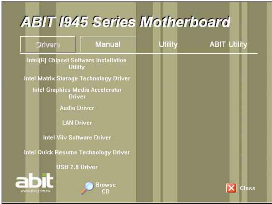
- [Drivers]: Click to enter the driver installation menu.
The "Intel Viiv Software Driver" and "Intel Quick Resume Technology Driver" are only necessary for WinXP MCE version. - [Manual]: Click to enter the user's manual menu.
- [Utility]: Click to enter the utilities installation menu.
-
[ABIT Utility]: Click to enter the installation menu of utilities exclusively developed by ABIT.
-
[Browse CD] : Click to browse the contents of this "Driver & Utility CD".
- [Close]: Click to exit this installation menu.
4.1 Intel Chipset Software Installation Utility
This utility installs Windows [INF] files to the target system. These files outline to the operating system how to configure the Intel chipset components in order to ensure all the features function properly.
To install this utility:
- Click on the [Drivers] tab in the installation menu screen.
- Click the [Intel Chipset Software Installation Utility] item. The installation screen appears:
Intel(R) Chipset Software Installation Utility 7.2.2.1006
intel
Welcome to the Intel(R) Chipset Software Installation Utility.
This program will install the Plug and Play components for the Intel(R) chipset that is on this system. It is strongly recommended that you exit all Windows programs before continuing.
<Back
Next>
Cancel
Intel(R) Installation Frameworks
- Follow the prompts on the screen to complete installation.
- Restart the system for the driver to take effect.
4.2 Intel Matrix Storage Technology Driver
This driver provides functionality for the on-chip SATA Controller.
※ This driver installation is necessary for connectors SATA1~SATA2 only when after having enabled the RAID function in the BIOS setup menu.
The path to enable the RAID function in the BIOS setup menu is: Integrated Peripherals OnChip IDE Device SATA Mode Select "RAID".
To install this driver:
- Click on the [Drivers] tab in the installation menu screen.
- Click the [Intel Matrix Storage Technology Driver] item. The following screen appears:
Intel(R) Matrix Storage Manager 6.0.0.1022

Welcome to the setup for the Intel(R) Matrix Storage Manager.
This setup program will install Intel(R) Matrix Storage Manager onto your computer. It is strongly recommended that you exit all Windows programs before continuing setup.
<Back
Next>
Cancel
Intel(R) Installation Frameworks
- Follow the prompts on the screen to complete installation.
- Restart the system for the driver to take effect.
4.3 Intel Graphics Media Accelerator Driver
This driver provides functionality for the on-chip Graphics Controller.
To install this driver:
- Click on the [Drivers] tab in the installation menu screen.
- Click the [Intel Graphics Media Accelerator Driver] item. The installation screen appears:
Intel(R) Graphics Media Accelerator Driver
intel
Welcome to the setup for the Intel(R) Graphics Media Accelerator Driver.
This program will install the Intel(R) Graphics Media Accelerator Driver on this computer. It is strongly recommended that you exit all Windows programs before continuing.
<Back
Next>
Cancel
Intel(R) Installation Frameworks
- Follow the prompts on the screen to complete installation.
- Restart the system for the driver to take effect.
4.3.1 Tips on HDMI application
- Connects to your HDMI device from the connector "HDMI1" only with an HDMI-to-HDMI cable. DO NOT connect with an HDMI-to-DVI cable.
- Connect your HDMI digital device to port "HDMI1" located at the rear I/O panel of this motherboard.
- Select the type of display device. For "HDMI" connection, you will have to configure the BIOS parameter:
(1) Enter the BIOS Setup Menu: "Advanced Chipset Features" "HDMI Port Display".
(2) Change the option from the default [DVI] to [Normal].
- After completed the driver installation of "Intel Graphics Media Accelerator", if there is no graphics output when restarting the system, try enter Hot Keys <Ctrl> + <Alt> + <F1> simultaneously to regain.
- For the application of HDMI digital device:
(1) Check to see if the screen resolution in the [Display Properties] is limited to "720 x 480" or lower than the one of your HDMI digital device.
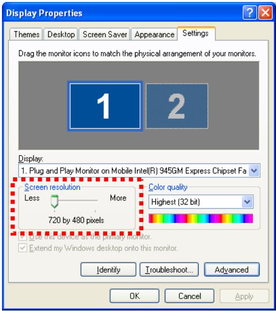
(2) If it does, uncheck the item "Hide modes that this monitor cannot display" in the "Monitor settings" via the path: [Control Panel] [Display Properties] [Settings] [Advanced] [Monitor].
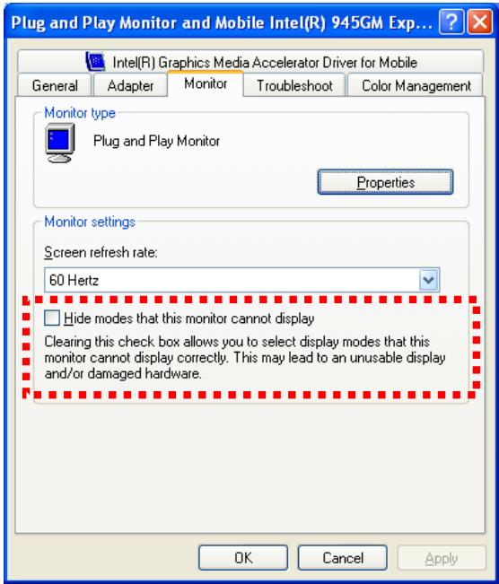
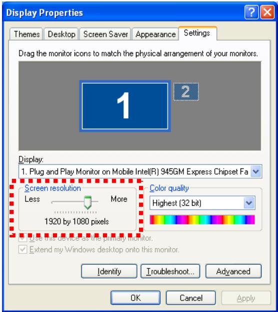
(3) Now you can raise the screen resolution from the [Display Properties] to the one of your HDMI digital device.
- Also, please remember that you will have to re-configure the "Display Device" every time after disconnecting HDMI cable.
For example: If you pull out the HDMI cable from the HDMI port, no matter when the system power is on or off, and then plug it back in the same HDMI port, you must enter Hot Keys Ctrl + Alt + F4 simultaneously to regain the video output for digital display.
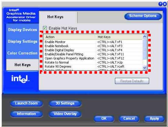
The "Hot Keys" combinations for video output selections are:
(1) Ctrl> + Alt> + F1> for enabling monitor.
(2)
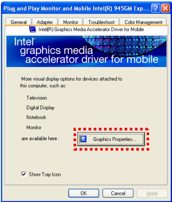
- You may find the default "Hot Keys" combination via the path: [Control Panel] [Display Properties] [Settings] [Advanced] [Intel(R) Graphics Media Accelerator Drive for Mobile] [Graphics Properties...].
4.4 Realtek Audio Driver
This driver provides functionality for the onboard High Definition Audio Codec.
To install this driver:
- Click on the [Drivers] tab in the installation menu screen.
- Click the [Audio Driver] item. The installation screen appears:
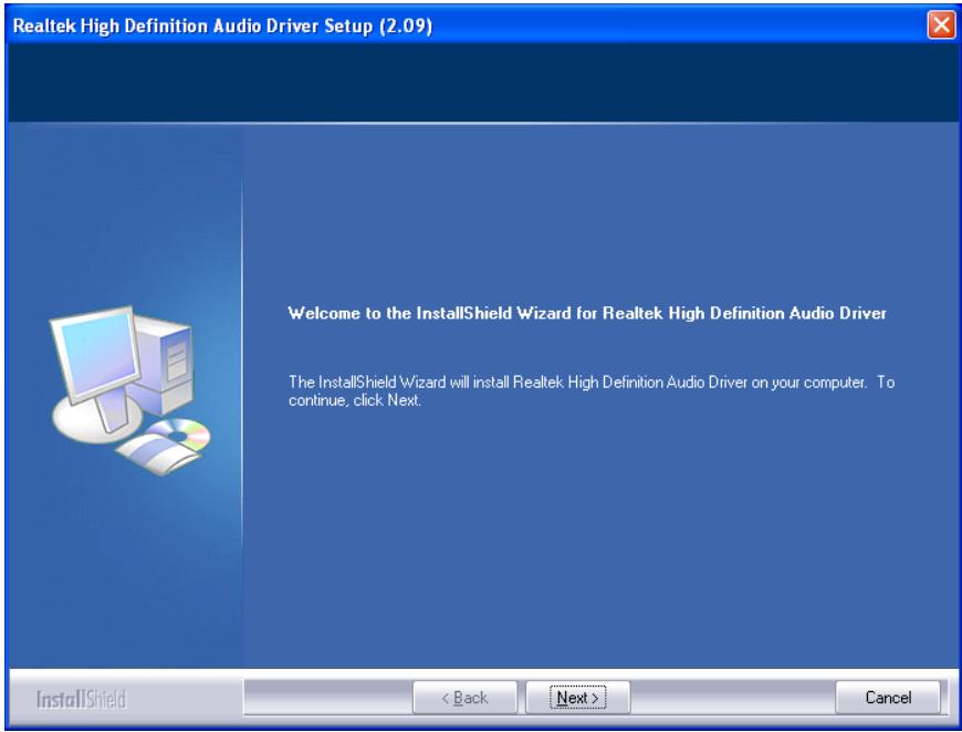
- Follow the prompts on the screen to complete installation.
- Restart the system for the driver to take effect.
4.5 Intel PRO Network Connections Driver
This driver provides functionality for the onboard Intel Gigabit Network Controller.
To install this driver:
- Click on the [Drivers] tab in the installation menu screen.
- Click the [LAN Driver] item. The installation screen appears:
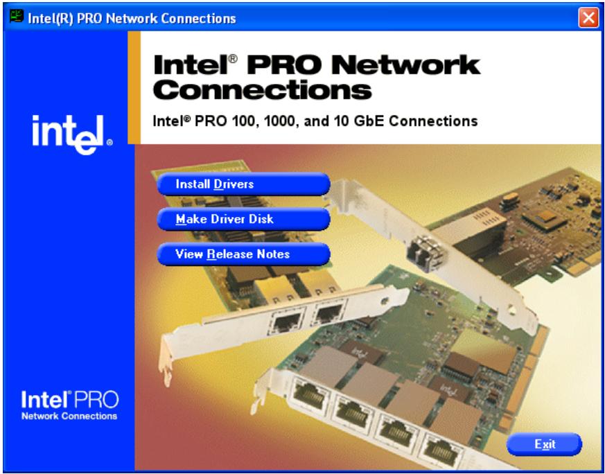
- Follow the prompts on the screen to complete installation.
- Restart the system for the driver to take effect.
4.6 USB 2.0 Driver
※ There is no need to install this driver for Windows 2000 with Service Pack 4, Windows XP with Service Pack 1, or their later version.
4.7 Intel SATA Driver Disk Maker
This procedure is necessary if you want to install operating system to a RAID configuration connected among "SATA1~SATA2" connectors:
- Prepare a 3.5'' floppy disk drive and connect it to "FDC1" connector on this motherboard.
- Start install operating system.
- Insert this driver disk into floppy disk drive when the screen instruction prompts you to install a third-party SCSI or RAID driver.
- Press <F6> key, and then follow the screen instruction to complete the installation.
To create a driver disk:
- Click on the [Utility] tab in the installation menu screen.
- Click the [Intel SATA Driver Disk Maker] item. The installation screen appears:
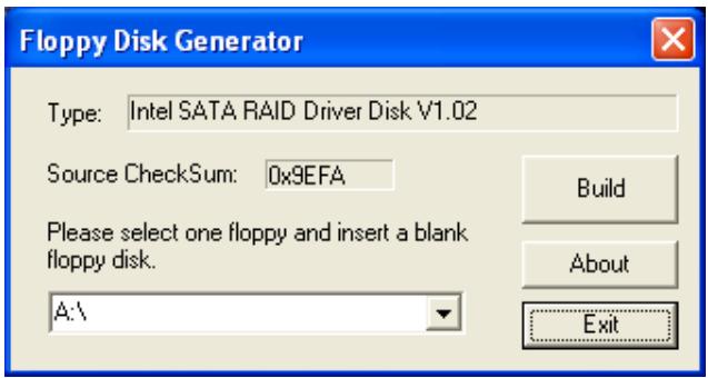
Insert one blank floppy disk to the selected floppy drive and click [Build].
- Click [OK] to finish building the SATA Driver Disk.
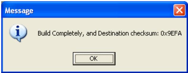
- Click [Exit] to exit the Floppy Disk Generator.
4.8 ABIT EQ (The Hardware Doctor Utility)
ABIT EQ is a self-diagnostic system for PC based on motherboards designed and manufactured by ABIT Computer Corporation. It will protect PC Hardware by monitoring critical items of Power Supply Voltage, CPU & System Fans Speed, and CPU & System Temperature.
To install this utility:
- Click on the [ABIT Utility] tab in the installation menu screen.
- Click the [ABIT EQ] item. The installation screen appears:
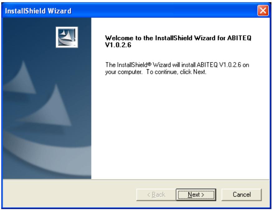
- Follow the prompts on the screen to complete installation.
-
Restart the system for the driver to take effect.
-
Execute the ABIT EQ by entering the Windows Menu [Start] [All Programs] [ABIT] [ABIT EQ].
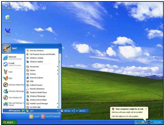
- ABIT EQ shows you the status of Voltage, Fan Speed, and Temperature readings as well.

4.9 FlashMenu (BIOS Update Utility)
ABIT FlashMenu is the most stable Windows-based BIOS flash available. No more worries from crashing. With one click of BIOS updating, ABIT users can flash their BIOS more easily and in less time.
To install this utility:
- Click on the [ABIT Utility] tab in the installation menu screen.
- Click the [FlashMenu] item under the [ABIT Utility] tab. The following screen appears:
- Follow the prompts on the screen to complete installation.
- Restart the system for the driver to take effect.
5. Appendix
5.1 Troubleshooting (How to Get Technical Support?)
5.1.1 Q & A
Q: Do I need to clear the CMOS before I use a new motherboard to assemble my new computer system?
A: Yes, we highly recommend that you clear the CMOS before installing a new motherboard. Please move the CMOS jumper from its default 1-2 position to 2-3 for a few seconds, and then back. When you boot up your system for the first time, follow the instructions in the user's manual to load the optimized defaults.
Q: If my system hangs when I update the BIOS or set the wrong CPU parameters, what should I do?
A: Whenever you update the BIOS or if the system hangs due to wrong CPU parameters setting, always clear CMOS jumper before booting up again.
Q: Why does the system fail to boot up again right after a mechanical power-off?
A: Please keep a 30-second interval between each mechanical power On/Off.
Q: Why does the system fail to boot up and nothing displays on the screen after I did some over-clocking or non-standard settings inside the BIOS?
A: It should not cause hardware or permanent damage to motherboard when BIOS settings were changed from default to over-clocking or non-standard status.
We suggest the following three troubleshooting methods to discharge CMOS data, recover the hardware default status, and then making the motherboard work again. There is no need to bother returning the motherboard to where you bought it from or go through an RMA process.
Step 1. Switch off the power supply unit and then switch it on again after one minute. If there is no power-switch on the power supply unit, disconnect its power cord for one minute and then reconnect.
Press and hold the key to enter the BIOS setup page to apply the correct settings.
If the situation remains the same, repeat the procedures in Step 1 for three times, or try Step 2.
Step 2. Switch off the power supply unit or disconnect the power cord. Open the chassis cover. Locate the CCMOS jumper near the button battery. Change the jumper position from default 1-2 to 2-3 for one minute to discharge the CMOS data, and then put it back to default 1-2 position.
Close the chassis and switch on the power supply unit or plug in the power cord. Press the power-on button to boot up system. If it works, hit key to enter the BIOS setup page to do the correct settings.
If the situation remains the same, try Step 3.
Step 3. The same procedure as Step 2, but while discharging the CMOS data, pull out the ATX power connectors from motherboard and remove the button battery during CMOS discharge.
Q: How to get a quick response for my request on technical support?
A: Please carry out a simple troubleshooting before sending "Technical Support Form":
System boot-up fails after the system had been assembled:
Check the motherboard's supporting specifications first to see if all the key components attached in your system can meet.
To do so, you may:
Remove all the unnecessary add-on devices (except the CPU, VGA card, DRAM, and Power Supply), and then reboot.
If the trouble still exists, try another VGA card of different brand/model to see if the system will start.
If the trouble still exists, try another memory module of different brand/model.
If the trouble still exists, try another CPU and Power Supply.
If the system runs successfully, shut it down and start re-installing the interface cards and devices that were previously installed in the system. Re-install and start the system one at a time until the system won't start.
Malfunction in the OS:
If the system hangs after resuming from S3 or some testing program, if the CPU cannot be recognized properly, if the display resolution mixed, or if a certain program cannot be executed, etc, you may:
Upgrade the motherboard's latest BIOS version.
Upgrade the add-on device's latest driver version.
Check if there is any conflict in the "Control Panel/System Properties".
Q: How to fill in the "Technical Support Form"?
A: To fill in this "Technical Support Form", please refer to the following instructions:
Region: Type in your country name.
E-mail: Type in your contact E-mail information.
- First name: Type in your first name.
- Last name: Type in your last name.
- Subject: Type in the model name and the problem of your motherboard. Example 1: AA8XE and SCSI 29160 malfunction Example 2: AA8XE boot fails, POST code AF Example 3: AA8XE (system hang when S3 resume)
- Motherboard: Type in the model name and revision number of your motherboard. Example: AA8XE REV: 1.00
BIOS Version: Type in the BIOS version of your motherboard. (You can find it on the screen during the POST sequence.)
- CPU: Type in the brand name and the speed (MHz) of your CPU. (Illustrate the over-clocking status if you had done so.) Example: Intel 650 3.4GHz (OC FSB=220MHz)
- Memory brand: Type in the brand and model name of your memory module. Example: Memory brand: Kingston (KVR533D2N4/1G)
Memory size: Type in the size of your memory module. Example: 512M* 4PCS
Memory configuration: Type in the memory configuration in BIOS setting. Example: Memory Timing: 2.5-3-3-7 @533MHz - Graphics card: Type in the brand and model name of your graphics card. Example: ATI RADEON X850 XT PE
- Graphics driver version: Type in the driver version of your graphics card Example: Catalyst 5.12V
- Power supply maker: Type in the brand and model name of your power supply unit.
- Power supply wattage: Type in the power wattage of your power supply unit.
Storage devices: Type in the brand and specifications of your HDD drive and quantity. Specify if it was inserted on IDE (Master or Slave) or SATA ports, including the RAID allocation status. Example 1: WD Caviar WD600 60GB (on IDE2 master), Maxtor DiamondMax 10 SATA 300GB (on SATA 3) Example 2: Maxtor DiamondMax 10 SATA 300GB *2 (on SATA 3, SATA 4 RAID 1) - Optical devices: Type in the brand and specifications of your optical drives and quantity. Specify if it was inserted on IDE (Master or Slave) or SATA ports.
- Other devices: Indicate which add-on cards or USB devices that you absolutely sure are related to the problem. If you cannot identify the problem's origin, indicate all the add-on cards or USB devices inserted on your system. Example: AHA 29160 (on PCI 2), Sandisk Cruzer mini 256MB USB Flash-disk.
- Operating system: Indicate which OS and language version Example: Microsoft Windows XP SP2, English version Example: Microsoft Media Center Edition 2005, Korean version
- Problem description: Describe the problem of your system configuration. Indicate the steps to duplicate problem if possible.
See the next page for a blank Technical Support Form, or visit our website to fill in the form on line (http://www.abit.com.tw/page/en/contact/technical.php).
Q. Is the motherboard dead? Do I need to return it to where I bought from or go through an RMA process?
A: After you had gone through the troubleshooting procedures, yet the problem still exists, or you find an evident damage on the motherboard. Please contact our RMA center. (http://www2.abit.com.tw/page/en/contact/index.php?pFUN_KEY=18000&pTITLE IMG)
5.1.2 Technical Support Form
| Region: | |
| E-mail: | |
| First name: | |
| Last Name: | |
| Subject: | |
| Motherboard: | |
| BIOS Version: | |
| CPU: | |
| Memory brand: | |
| Memory size: | |
| Memory configuration: | |
| Graphics card: | |
| Graphics driver version: | |
| Power supply maker: | |
| Power supply wattage: | |
| Storage devices: | |
| Optical devices: | |
| Other devices: | |
| Operating system: | |
| Problem description: |
5.1.3 Universal ABIT Contact Information
Taiwan Head Office
Universal ABIT Co., Ltd.
No. 323, Yang Guang St., Neihu,
Taipei, 114, Taiwan
Tel: 886-2-8751-3380
Fax: 886-2-8751-3381
Sales: sales@abit.com.tw
Marketing: market@abit.com.tw
North America, South America
Universal ABIT (USA) Corporation
2901 Bayview Drive,
Fremont, CA 94538, U.S.A.
Tel: 1-510-623-0500
Fax: 1-510-623-1092
Website: http://www.ubit-usa.com
Latin America:ventas@abit-usa.com
RMA Center: http://rma.abit-usa.com
UK, Ireland
Universal ABIT UK Corporation
Unit 3, 24-26 Boulton Road, Stevenage, Herts SG1 4QX, UK
Tel: 44-1438-228888
Fax: 44-1438-226333
Germany and Benelux (Belgium, Netherlands, Luxembourg), France, Italy, Spain, Portugal, Greece, Denmark, Norway, Sweden, Finland, Switzerland
Universal ABIT NL B.V.
Jan van Riebeeckweg 15, 5928LG
Venlo, The Netherlands
Tel: 31-77-3204428
Fax: 31-77-3204420
Austria, Czech, Romania, Bulgaria, Slovakia, Croatia, Bosnia, Serbia, Macedonia, Slovenia
Universal ABIT Austria Computer GmbH
Schmalbachstrasse 5, A-2201 Gerasdorf /
Wien, Austria
Tel: 43-1-7346709
Fax: 43-1-7346713
Contact: office@abit-austria.at
Website: http://www.abet-austria.at
Shanghai
Universal ABIT (Shanghai) Co. Ltd.
FL 19 Xuhui Yuan BLOG NO.1089
ZhongShan s 2 RD, ShangHai 200030
The People's Republic of China
Tel: (86-21) 54102211
Fax: (86-21) 54104791
Website: http://www.abit.com.cn
Poland
Universal ABIT Poland (Rep. office)
Strzegomska 310/2, 54-432 Wroclaw
Tel:+48-71-718-12-39
Contact: Grzegorz Morgiel
Russia
Universal ABIT Russia (Rep. office)
Tel: +749 570 05742
+749 554 27802
Turkey
Universal ABIT Turkey (Rep. office)
Tel: 90 532 211 6860
abit
UNIVERSAL ABIT Co., Ltd.
http://www.ubit.com.tw