
CS-2000 - Spectrophotomètre KONICA - Notice d'utilisation et mode d'emploi gratuit
Retrouvez gratuitement la notice de l'appareil CS-2000 KONICA au format PDF.

| Type de produit | Spectrophotomètre (spectroradiomètre) |
| Marque | Konica Minolta Sensing |
| Modèle | CS-2000 |
| Dimensions (L×H×P) | 158 × 200 × 300 mm (objectif : ø70 × 95 mm) |
| Poids | 6,2 kg |
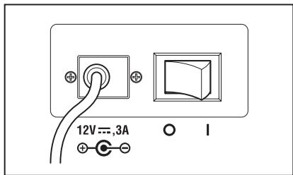
| Alimentation | Adaptateur secteur AC-A312 : entrée 100–120 V~ ou 200–240 V~, 50/60 Hz ; sortie 12 V=, 3 A |
| Plage de mesure de luminance | 0,003 à 5 000 cd/m² (angle 1°) ; 0,075 à 125 000 cd/m² (0,2°) ; 0,3 à 500 000 cd/m² (0,1°) |
| Précision luminance (source A) | ±2 % |
| Précision chromatique (source A) | x, y : ±0,003 (basse luminance) à ±0,001 (haute luminance) |
| Répétabilité luminance (2 σ) | 0,15 % à 0,4 % selon la luminance |
| Angles de mesure | 1°, 0,2°, 0,1° (sélecteur rotatif) |
| Espace colorimétrique | Lvxy, Lvu'v', LvTΔuv, XYZ, longueur d'onde dominante/pureté d'excitation, graphe spectral |
| Modes de synchronisation | Non synchro, synchro interne (INT), synchro externe (EXT) |
| Temps de pose | Rapide : 0,005–16 s ; Normal : 0,005–120 s ; Multiple intégration ; Manuel : 5–120 000 ms |
| Interface de communication | USB 1.1 |
| Mémoire interne | 100 valeurs (numéros 00–99) |
| Calibration | 11 canaux (Ch00 usine fixe, Ch01–10 utilisateur avec logiciel CS-S10w) |
| Température de fonctionnement | 5 à 35 °C, HR ≤ 80 % sans condensation |
| Température de stockage | 0 à 45 °C, HR ≤ 80 % sans condensation |
| Entretien | Nettoyer le boîtier avec un chiffon sec et doux ; objectif avec chiffon ou papier optique. Ne pas utiliser de solvants organiques. Vérification annuelle recommandée. |
| Sécurité | Ne pas utiliser en présence de gaz inflammables. Utiliser uniquement l'adaptateur fourni. Ne pas démonter. Ne pas regarder le soleil ou une source intense à travers le viseur. |
| Accessoires inclus | Cache-objectif CS-A31, câble USB 2 m, adaptateur secteur AC-A312, certificat d'étalonnage, logiciel CS-S10w Professional |
| Accessoires optionnels | Filtre ND (1/10, 1/100), lentille de proximité, plaque de calibration blanche, trépied, mallette de transport |
FOIRE AUX QUESTIONS - CS-2000 KONICA
Questions des utilisateurs sur CS-2000 KONICA
0 question sur cet appareil. Repondez a celles que vous connaissez ou posez la votre.
Poser une nouvelle question sur cet appareil
Téléchargez la notice de votre Spectrophotomètre au format PDF gratuitement ! Retrouvez votre notice CS-2000 - KONICA et reprennez votre appareil électronique en main. Sur cette page sont publiés tous les documents nécessaires à l'utilisation de votre appareil CS-2000 de la marque KONICA.
MODE D'EMPLOI CS-2000 KONICA
SPECTRORADIOMETER CS-2000
Instruction Manual
Safety Symbols
The following symbols are used in this manual to prevent accidents which may occur as a result of incorrect use of the instrument.

Denotes a sentence regarding a safety warning or note.
Read the sentence carefully to ensure safe and correct use.

Denotes a prohibited operation.
The operation must never been performed.

Denotes an instruction.
The instruction must be strictly adhered to.

Denotes an instruction.
Disconnect the AC adapter from the AC outlet.

Denotes a prohibited operation.
Never disassemble the instrument.
Notes on This Manual
- Copying or reproduction of all or any part of the contents of this manual without KONICA MINOLTA SENCING's permission is strictly prohibited.
- The contents of this manual are subject to change without prior notice.
- Every effort has been made in the preparation of this manual to ensure the accuracy of its contents. However, should you have any questions or find any errors, please contact the nearest KONICA MINOLTA SENCING-authorized service facility.
- KONICA MINOLTA SENCING will not accept any responsibility for consequences arising from the use of the instrument.
Safety Precautions
To ensure correct use of this instrument, read the following points carefully and adhere to them. After you have read this manual, keep it in a safe place where it can be referred to anytime a question arises.
| Warning (Failure to adhere to the following points may result in death or serious injury.) | |
| Do not use this instrument in places where flammable or combustible gases (gasoline etc.) are present. Doing so may cause fire. | |
| Always use the AC adapter and power cord supplied as a standard accessory or optional (AC-A312), and connect it to indoor AC outlet of rated voltage and frequency (100 - 120 V~or 200 - 240 V~, 50/60Hz). Failure to follow either of these may result in damage to unit, fire or electric shock. | |
| If this instrument is not used for a long time, disconnect AC adapter from AC outlet. Accumulated dirt or water on prongs of AC adapter plug may cause fire and should be removed. | |
| Do not forcibly pull any part on power cord when unplugging since this may cause fire or electric shock. Gently disconnect by holding plug. Also, do not handle power cord with wet hands. Doing so may cause electric shock. | |
| Do not forcibly bend, twist or pull power cord. Also, do not place heavy object on power cord, or damage or modify one. Any of these may cause fire or electric shock due to damage to power cord. | |
| Do not disassemble or modify this instrument or AC adapter. Doing so may cause fire or electric shock. | |
| Do not spill liquid on this instrument or drop metal into this instrument. Should either of these happen, switch power off, unplug AC adapter immediately and contact the nearest KONICA MINOLTA SENSING authorized service facility. | |
| Should this instrument or AC adapter be damaged or smoke or odd smell be generated, do not keep using such instrument or AC adapter without correction. Doing so may cause fire. In such situations, switch power off immediately, unplug AC adapter and contact the nearest KONICA MINOLTA SENSING authorized service facility. | |
| Do not look at sun or intense light through finder of this instrument. This may lose your sight. | |
| Caution (Failure to adhere to following points may result in injury or damage to this instrument or other property.) | |
| Use this instrument near AC outlet for easy plugging or unplugging in using AC adapter. | |
| Do not place this instrument on unstable or sloping surface which may drop or overturn it. Dropping or overturning may injure someone around. Take care not to drop this instrument when carrying it. | |
| Do not move while looking inside finder since this would fall or injure user. | |
| Take special care in handling the ND filter or closeup lens included in the optional accessories. Breakage of the ND filter or closeup lens may injure someone around. |
Introduction
This instrument is a high-accuracy spectroradiometer designed to measure luminance and chromaticity up to super-low luminance regions. Carefully read this manual before using one.
Packaging material
Be sure to save all packaging materials (corrugated cardboard boxes, pads and plastic bags) supplied with the purchase. This is delicate measurement instrument. Use packaging materials supplied in purchasing in case this instrument needs to be transferred for such purpose as maintenance in KONICA MINOLTA SENSING's factories. These packaging materials are useful for minimizing shock or vibration to this instrument in such situation. Should any of these packaging materials be lost or broken, please contact the nearest KONICA MINOLTA SENSING authorized service facility.
Note on Use
Operating Environment
- The standard AC adapter (AC-A312) of this instrument is designed specifically for use indoors. Do not use it outdoors.
- Do not disassemble this instrument for being composed of delicate electronic components.
- Use this instrument at rated voltage of 100 ~V - 120 ~V or 200 ~V - 240 ~V (50 / 60 ~Hz) . Connect AC power cord to AC outlet with rated voltage and frequency. Connected voltage should not be outside the range of ± 10 % of nominal.
- This instrument is classified into a Pollution Degree 2 as instrument used in mainly in manufacturing plant, laboratory, warehouse or equivalents. Use this instrument in metal dust free and non condensing potential environment.
- This instrument is categorized into Installation Category II as equipment connected to commercially available power source.
- Connect PC for controlling this instrument to the outlet with protective grounding. Failure to follow this may result in electric shock due to short circuit.
- Take care not to enter foreign substance like water or metal in this instrument. Operating in such state cause serious danger.
- Do not use this instrument under direct sunlight or near heater. The internal temperature of this instrument to become much higher than ambient temperature which may break this instrument.
Also, use this instrument in a well-ventilated place. To ensure proper heat dissipation, keep the ventilation holes free from obstructions.
- Avoid rapid change in ambient temperature which may form dew condensation.
- Avoid using this instrument in extremely dusty or humid place.
- Use this instrument at ambient temperature between 5 and 35^ and relative humidity 80% or less (at 35^ ) with no condensation. Operating this instrument outside specified temperature and humidity range may not satisfy its original performance.
This Instrument
- Do not subject this instrument to strong impact or vibration.
- Do not forcibly pull, bend, or apply strong force to power cord for attached AC adapter or USB cable. This may result in snapping.
- Connect this unit to power source with minimal noise.
- Do not measure a high-luminance light source (including sunlight) beyond the measurement range. The failure to observe this warning could result in damage to the optical system.
- Should breakage or abnormality be found during operation, switch power off immediately and unplug. Then refer to "Error Check" on page 82.
- Should this instrument break down, do not try to disassemble and repair it by yourself. Please contact the nearest KONICA MINOLTA SENSING authorized service facility.
- Warm this instrument up for 20 minutes at least after switching power on when the object luminance is 2cd / m^2 or lower (measuring angle 1^ ).
Objective lens, ND filter and Closeup lens (Optional Accessories)
- Make sure that surfaces of objective lens, ND filter or closeup lens are clear. Correct measurement may not be performed if there is dirt, dust, hand soil or part left unclean.
- Do not touch surface of objective lens, ND filter or closeup lens with hand.
- Do not change ambient temperature rapidly under high humidity. This may mist objective lens, ND filter or closeup lens, resulting in incorrect measurement.
Note on Use
Body
- Do not store this instrument under direct sunlight or near heater. The internal temperature of this instrument becomes much higher than ambient temperature which may break this instrument.
- Store this instrument at ambient temperature between 0 and 45^ and relative humidity 80% or less (at 30^ ) with no condensation. Storage under high temperature and humidity may deteriorate performance of this instrument. For added safety, we recommend storage with such drying agent at room temperature.
- Take care not to form condensation. Avoid rapid change in ambient temperature when transferring body for storage.
- Put the body in a packaging box supplied when purchased or the storage case (CS-A30) in the optional accessories to store in safe place.
Objective lens
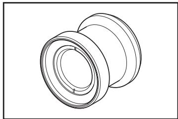
- For storage, cover the objective lens with standard accessory lens cap.
Cleaning
Body
- If this unit becomes dirty, wipe with dry and soft cloth. Do not use organic solvent like benzine or thinner and other chemical agent for cleaning. Should none of these methods be helpful, please contact the nearest KONICA MINOLTA SENSING authorized service facility.
Objective lens
- Should it be gotten dirt or dust, wipe off with dry and soft cloth or lens cleaning paper. Do not use organic solvent like benzine or thinner and other chemical agent for cleaning. Should none of these methods be helpful, please contact the nearest KONICA MINOLTA SENSING authorized service facility.
Notes on transfer
- Use packaging material supplied when purchased to minimize vibration or shock generated during transfer.
- Put all material including unit and accessories in original packaging material when returning this instrument for service.
Maintenance
- Periodical checkup is recommended annually to maintain measurement accuracy of instrument. For details on checkup, please contact the nearest KONICA MINOLTA SENSING authorized service facility.
Contents
Safety Precautions 1
Introduction 3
Note on Use 3
Operating Environment 3
This Instrument 4
Objective lens, ND filter and Closeup lens (Optional Accessories) 4
Note on Use 4
Body 4
Objective lens 4
Cleaning 5
Body 5
Objective lens 5
Notes on transfer 5
Maintenance 5
Standard Accessories 8
Optional Accessories 9
System Configuration 11
Names and Functions of Parts 12
Names of Each Part 12
Functions of Each Part 13
Key Panel 14
Main Functions of Each Key 14
Diopter Adjustment 15
LCD Screen 16
MEAS (Measurement value) screen 16
MENUscreen 17
Installation
Installing 20
Connecting AC Adapter 21
Connection Method 22
Power Switch ON(|)/OFF(O) 23
Turning power switch ON 23
Turning power switch OFF. 23
Setting
Setting of Synchronization 26
Selecting Measurement Time 30
Setting Observer 34
Selecting Display Format 36
Selecting Color Space 38
Selecting Absolute Value (ABS)/
Difference (DIFF) Display 40
When Using Closeup Lens 42
When Using ND Filter 44
Calibration 46
Calibration Channel 46
Backlight ON/OFF During
Measurement 48
Measurement
Measurement 52
Saving the Measurement Value..... 55
Deleting the Memory Data 58
Registering Target Color 61
Target color 61
Selecting Target Color 65
Deleting Target Color 67
Communication
Connecting to PC 72
Remote Mode 73
Explanation
Measurement Principle 76
Sensor Section 76
Dark Measurement 76
LvTΔuv 77
Dominant wavelength/Excitation purity... 78
Measurement of Object Color 79
Necessary Setting for Object Color Measurement ... 79
White Calibration 79
Measurement of Object 79
Dimensions 80
Error Message 81
Error Check 82
Setting Initialization 85
Switching Luminance Unit 86
Main Specifications 87
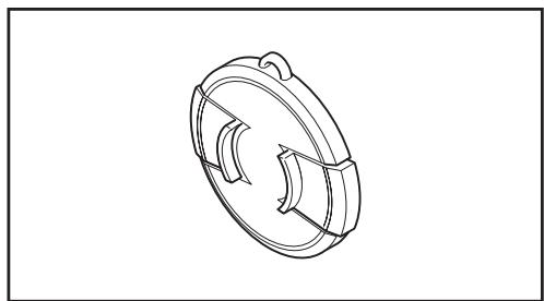
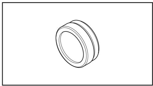
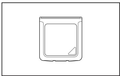
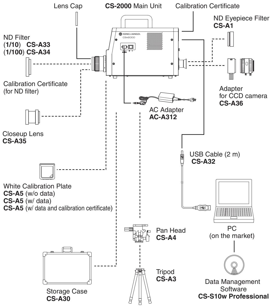
Lens Cap CS-A31
- Attached to objective lens for protecting it when not using this instrument.
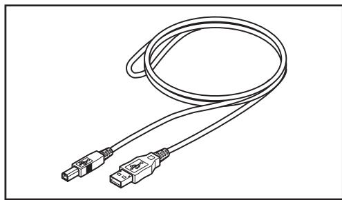
USB Cable (2 m) CS-A32
- Used for communication between this instrument and PC.
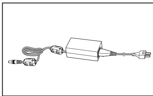
AC Adapter AC-A312
- Supplies power from AC outlet.
Input: 100 - 120 V ~ or 200 - 240 V ~ 0.75 - 0.42 A 50/60 Hz
Output: 12 V = 3 A
Calibration Certificate
Data Management Software CS-S10w Professional
- Software to control this instrument from PC for various data management.
- The protect key is attached.
Optional Accessories
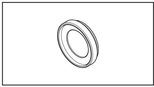
ND Eyepiece Filter CS-A1
- Reduces glare during observation through the finder when a high-luminance object is measured. Be sure to place this filter in front of the finder when measuring high-luminance objects.
ND Filter (1/10) CS-A33
ND Filter (1/100) CS-A34
- Placed in front of objective lens for measurement of high luminance object.
Calibration Certificate (for ND filter)
- Calibration certificates can be attached to the ND filters (1/10) CS-A33 and (1/100) CS-A34.
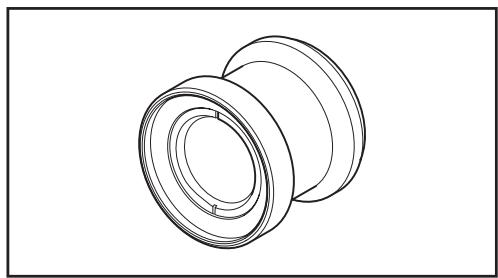
Closeup Lens CS-A35
- Placed in front of objective lens for measurement of small object.
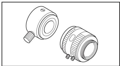
Adapter for CCD camera CS-A36
- Placed between the finder and the body when a C-mount industrial camera is used.
White Calibration Plate CS-A5 (without data) White Calibration Plate CS-A5 (with data) White Calibration Plate CS-A5 (with data and calibration certificate)
- Used for measurement of object colors. Three types (named, not-named, named with calibration certificate) are prepared.
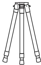
Tripod CS-A3
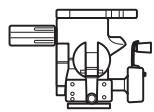
Pan Head CS-A4
Used when installing this instrument.
- Replace the pan head tripod screw with the screw included with this instrument.
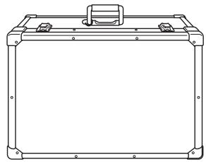
Storage Case CS-A30
- Soft case used to house the instrument and accessories or to carry them by hand. Never use this as a transport case.
Standard Accessories
- - - - - Optional Accessories
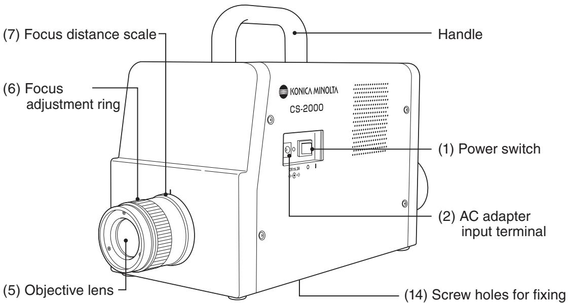
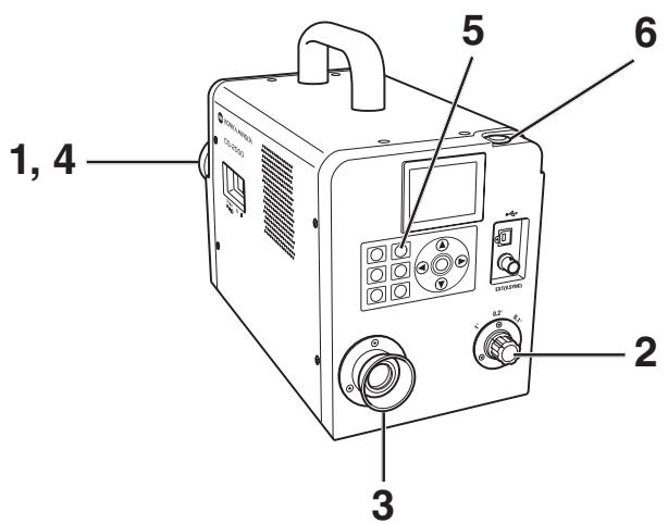
Names of Each Part
Functions of Each Part
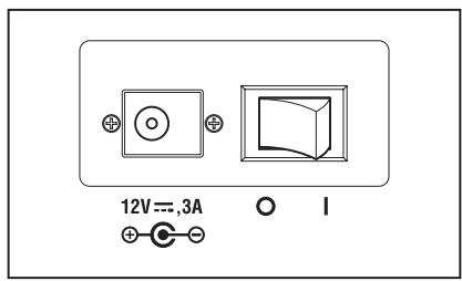
(1) Power switch Switches this instrument on/off. ( | ) for ON; (O) for OFF...(p.23)
(2) AC adapter input terminal Connects the attached AC adapter. (p.21)
(3) USB connector Connects the USB cable when connecting to PC. (p.72)
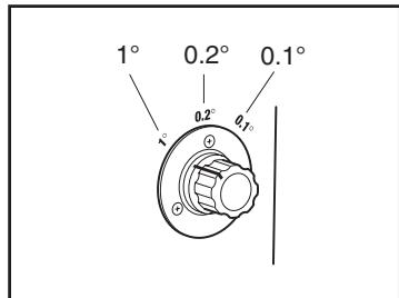
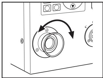
(4) Measuring angle selector Selects measurement angle among 1^ , 0.2^ and 0.1^ . (p.52)
(5) Objective lens Directed to object for measurement. (p.53)
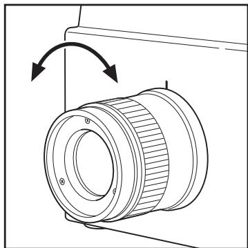
(6) Focus adjustment ring Adjusts focus of objective lens before measurement. (p.53)
(7) Focus distance scale Helps adjusting focus. (p.53)
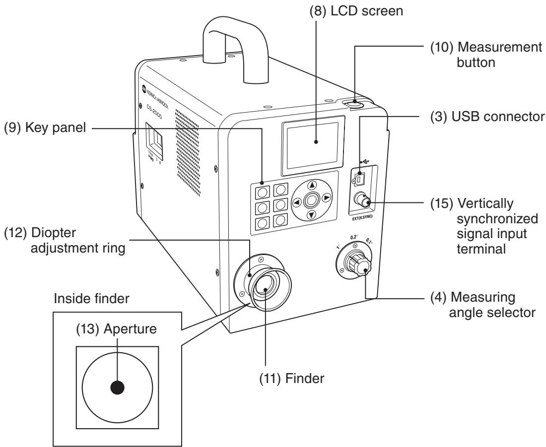
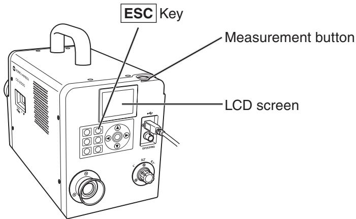
(8) LCD Screen Displays various screens like measurement and menu. ... (p.16)
(9) Key Panel Offers several keys for operation of this instrument. .... (p.14)
(10)Measurement button For measurement. When pressed during continuous ... (p.53) measurement, the measurement ends.
(11) Finder Used to observe object for measurement. (p.15, 53)
(12) Diopter adjustment ring Adjusts diopter. (p.15, 53)
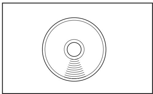
(13)Aperture Indicates measuring area. (p.53) Size of black circle will change depending on measuring angle.

1^ Aperture

0.2^ Aperture
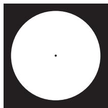
0.1^ Aperture
(14) Screw holes for fixing Used to fix this instrument with tripod or jig. (p.20)
(15) Vertically synchronized Connects the cable to input the vertically synchronized signal input terminal signal or the external sync measurement. (p.26)
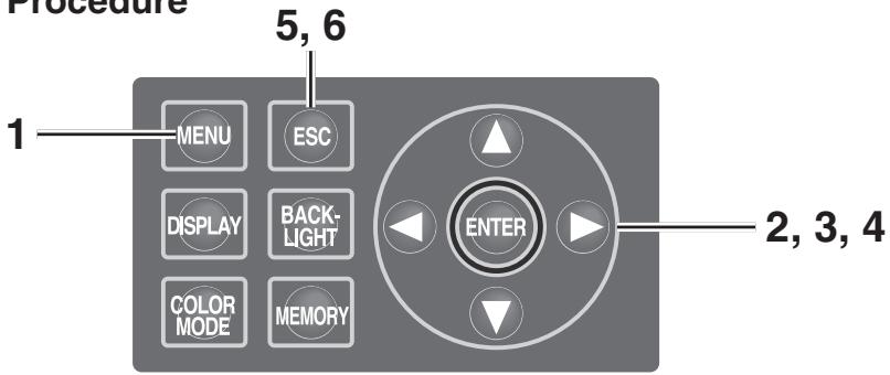
Key Panel
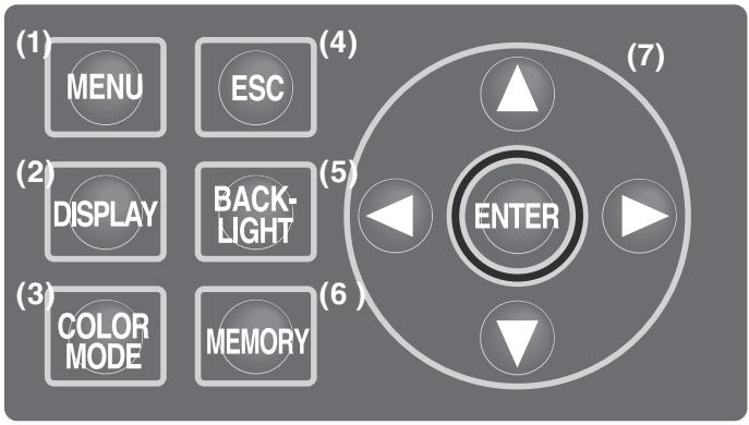
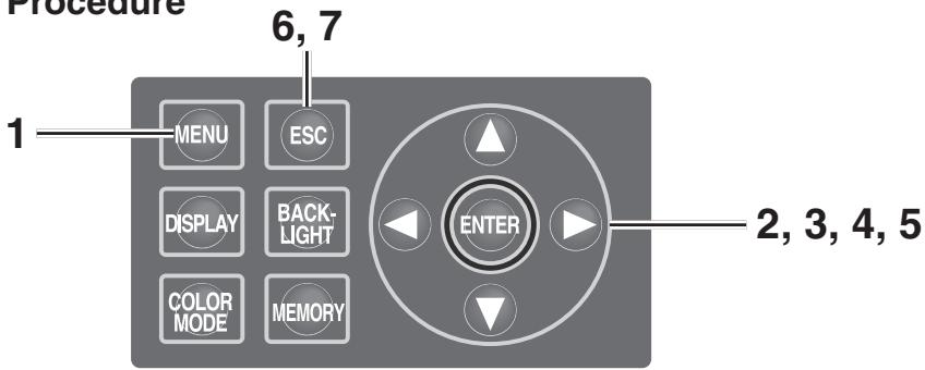
Main Functions of Each Key
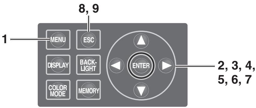
(1) MENU key
The MENU screen appears if this key pressed when the measurement value screen appears. (p.17)
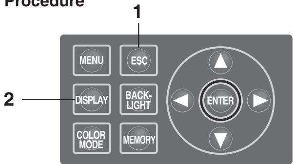
(2) DISPLAY key
Selects whether chromaticity is displayed in absolute value (ABS) or difference (DIFF) if this key pressed when the measurement value screen appears. (p.40)
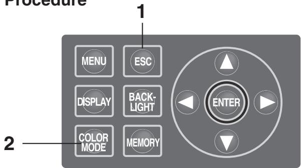
(3) COLOR MODE key
Color space modes are switched in turn as follows, by pressing the key when the measurement value screen appears: L_vxy L_vu'v' L_vT uv XYZ Dominant wavelength/Excitation purity →Spectral graph → L_vxy . (p.38)
(4) ESC key
If this key is pressed when the MENU screen is displayed, the settings are canceled and the measurement value screen appears again. If pressed during numerical input or when making each setting, the settings are canceled. If pressed during continuous measurement, the measurement ends.
(5) BACKLIGHT key
Selects backlight ON/OFF on LCD screen. (p.48)
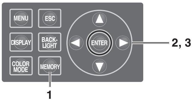
(6) MEMORY key
Measured data is stored in memory by pressing this key when the measurement value screen appears. (p.55)
(7) keys
Memory data, target color channels, calibration channels, etc., are changed by pressing the key when the screen for display of various data appears. The cursor position is moved up and down, or the values and set items are changed, by pressing the key during numerical input or when making each setting.


keys
The cursor position moves right and left by pressing the key for numerical input or when making each setting.
ENTER key
Press the key to fix the contents selected in
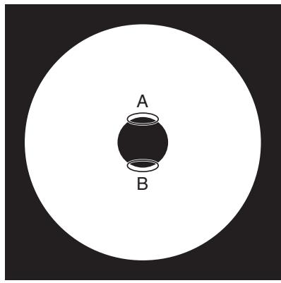
Diopter Adjustment
Rotate the diopter adjustment ring for adjustment of diopter.
Diopter adjustment ring
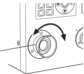
Adjust so that A or B on aperture or black circle indicating measuring area looks clear when observing object through finder.
Adjustment would be easy starting with 1^ aperture where object near aperture looks blur.
Make sure to adjust diopter before measurement. Diopter should be adjusted for the eyesight of the person who will be taking measurement. If diopter is not adjusted before focus measurement, correct measurement value may not be expected. This is because the focus is actually off even if you think it is correctly in focus. In addition, if diopter is not correctly adjusted, you may see the aperture moving depending on viewing angle.
- You sometimes see small black dots or stripes in internal finder. It gives no effect on measuring performance.
LCD Screen
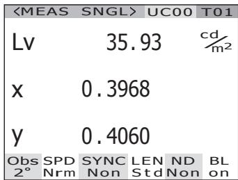
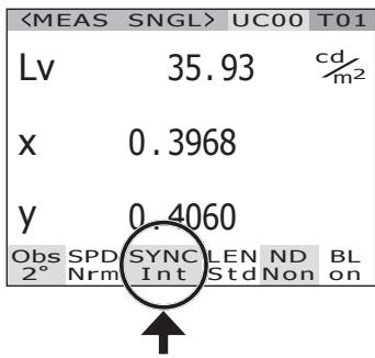
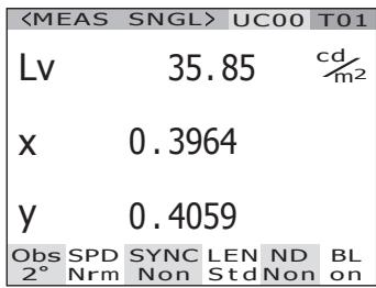
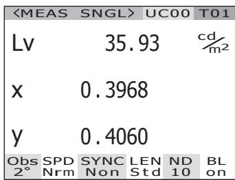
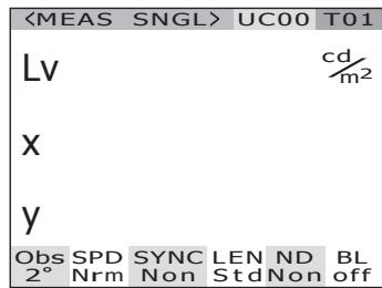
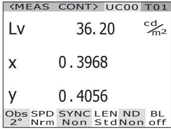
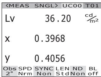
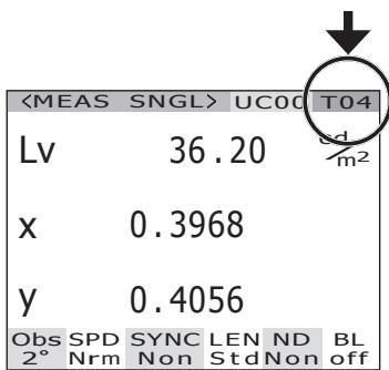
MEAS (Measurement value) screen
"SNGL" is displayed for the values obtained during single measurement, while "CONT" is displayed for the values obtained during continuous measurement. (p.53)
Calibration channel (p.46)
Target color channel
(p.61, 65, 67)
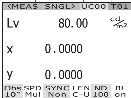
Measurement result is displayed in the currently selected color space. (L_,L_'v',L_ uv,XYZ, Dominant wavelength/Excitation purity, Spectral graph) (p.38) Display format can be changed. (p.36)
Setting status in this instrument is displayed.
Currently selected observer angle is displayed. (2^,10^) (p.34)
Currently selected measuring time is displayed. (Fst, Nrm, Mul, Mnl) (p.30)
"Int" is displayed when the internal sync measurement mode is set. "Ext" is displayed when the external sync measurement mode. "Non" is displayed when the sync measurement mode is not set. (p.26)
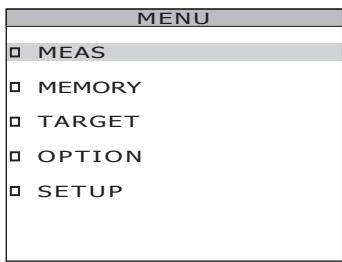
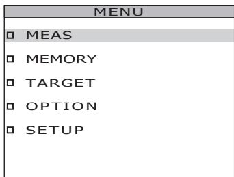
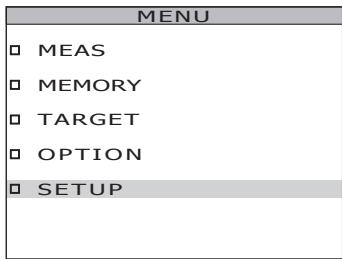
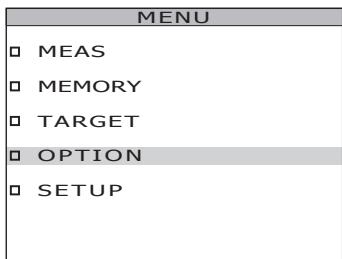
MENU screen
The MENU screen appears if MENU key is pressed when the measurement value screen is displayed.
MENU
MEAS
□ MEMORY
TARGET
□ OPTION
SETUP

MEAS
Used to set measurement time or synchronizing method. (p.26, 30)

MEMORY
Used to read or delete the measurement memory data. (p.56, 58)

TARGET
Used to register, select or delete the target color. (p.61, 65, 67)

OPTION
Used to set the closeup lens, ND filter or calibration channel. (p.42, 44, 46)

SETUP
Used to set the observer, backlight or display format. (p.34, 48, 36)
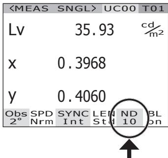
"C-U" is displayed, if the closeup lens is attached. If not, "Std" is displayed (p.42).
The current ND filter type is displayed. (Non, 10, 100) (p.44)
"On" is displayed, if the backlight is set to be turned on during the measurement. "Off" is displayed, if the backlight is set to be turned off during that time. (p.48)
Installation
Use screw holes for fixing at the bottom of this instrument if utilized with the tripod or jig. 2-type holes are available.
Tripod screw hole: To set on the tripod. Use a tripod screw with top diameter of 3/8 inches and depth of 8.5 mm .
[Note] The tripod screw holes correspond with the 3/8-inch screws of a large camera tripod. 1/4-inch screws cannot be used for fixing this instrument.
When using the pan head CS-A4 included in the optional accessories, replace the pan head tripod screw with the screw included with this instrument.
ISO screw hole: To set on the jig. Use ISO screws with top diameter of 5mm and depth of 6.5mm .
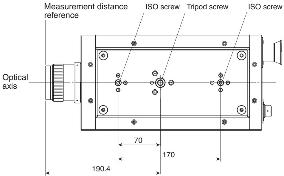
For other detailed dimensions, see p.80.
Connecting AC Adapter
The AC adapter supplied with this instrument is used for the corresponding power source.

Warning
(Failure to adhere to the following points may result in death or serious injury.)

Always use the AC adapter and power cord supplied as a standard accessory or optional accessory (AC-A312), and connect it to indoor AC outlet of rated voltage and frequency (100 - 120 V ~ or 200 - 240 V ~, 50/60Hz). Failure to follow either of these may result in damage to unit, fire or electric shock.

If this instrument is not used for a long time, disconnect AC adapter from AC outlet. Accumulated dirt or water on prongs of AC adapter plug may cause fire and should be removed before use.

Do not forcibly pull any part on power cord when unplugging since this may cause fire or electric shock. Gently disconnect by holding plug. Also, do not handle power cord with wet hands. Doing so may cause electric shock.

Do not forcibly bend, twist or pull power cord. Also, do not place heavy object on power cord, or damage or modify one. Any of these may cause fire or electric shock due to damage to power cord.

Do not disassemble or modify this instrument or AC adapter. Doing so may cause fire or electric shock.

Should this instrument or AC adapter be damaged or smoke or odd smell be generated, do not keep using such instrument or AC adapter without correction. Doing so may cause fire. In such situations, switch power off immediately, unplug AC adapter and contact the nearest KONICA MINOLTA SENSING authorized service facility.

Caution
(Failure to adhere to following points may result in injury or damage to this instrument or other property.)

Use this instrument near AC outlet for easy plugging or unplugging in using AC adapter.
Connection Method
- Make sure that power switch is OFF (slided to [O] side).
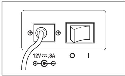
- Connect the AC adapter plug to the AC adapter input terminal of the body.
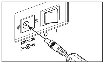
- Plug the AC adapter to outlet (100 - 120 VAC ~ or 200 - 240 VAC ~, 50 Hz/60 Hz).
Insert the AC adapter plug all the way seated in AC outlet.
The warm-up time needed is a minimum of 20 minutes in order to measure the objects with excellent accuracy under the conditions described below. Warm up this instrument for 20 or more minutes when the power source is turned off even for a short period, and turned on again.
(1) The object is a low-luminance light source, using 2856 K (standard light source A) as a guide: 2cd / m^2 or lower ( 1^ Aperture)
50 cd/m² or lower (0.2° Aperture)
200 cd/m² or lower (0.1° Aperture)
(2) Outside room temperature and normal humidity ranges
Turning power switch ON
1. Slide power switch to ON ( | ) side.
The measurement screen appears 5 seconds after the initial screen on the LCD.
The body version and product serial numbers are displayed in the initial screen.
Turning power switch OFF
2. Slide power switch to OFF (O side) after measurement.
Setting
Setting of Synchronization
The synchronized measurement refers to measurement mode where measurement is made in the same timing as periodical light source pulse frequency, such as vertically synchronized frequency for the display device.
[INT SYNC]
The internal sync measurement mode is used to measure the display equipment without the input of vertically synchronized signals to the body, or to measure flicker light from a light source such as a fluorescent light. Input the frequency of vertically synchronized signals for the display equipment, or the commercial frequency (50 or 60 Hz) for flicker light from a light source such as a luminescent light. The optimal integral action time is automatically set based on the input value and the brightness of the object. For this reason, enter the correct frequency value to two places of decimals.
However, if the vertically synchronized frequency of the display equipment is not clear, accurate measurement will not be possible with an inaccurate frequency setting. In this case it is recommended to select [NO SYNC] mode without sync measurement (at 60 Hz of frequency), but to select [MULTI INTEG] mode for the measurement time (refer to p. 30).
[EXT SYNC]
The external sync measurement mode is used to measure the display equipment after the line input of a vertically synchronized signal through the input terminal for vertically synchronized signals to the body. The optimal integral action time is set automatically, based on the frequency of vertically synchronized signals and the brightness of the object. Input CMOS (5V) Level of the input signals.
- Range of synchronized frequencies : 20.00 to 200.00 Hz
- Factory default setting : NO SYNC
![KONICA CS-2000 - [EXT SYNC] - 1](/content/2025/01/172147/images/7bc7dce35d64628c1377514ca9f3fe4bffd541e9cbb2f3ee3227b47acbad4132.jpg)
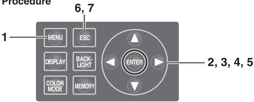
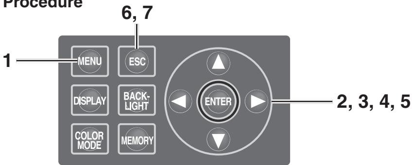
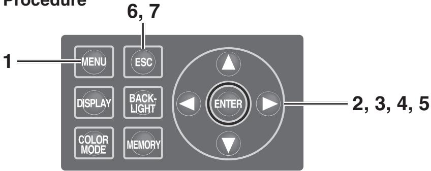
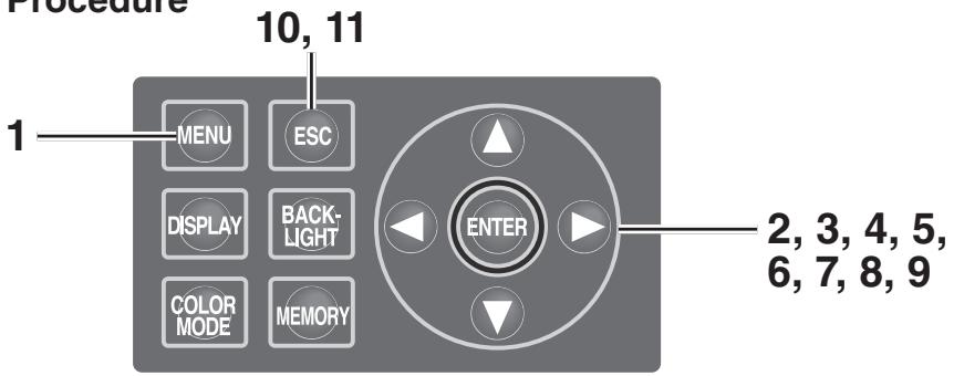
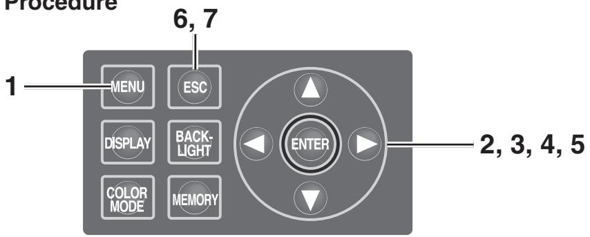
Operation Procedure
1. Press MENU key when the MEAS screen is displayed.
The MENU screen appears.
When the backlight of the LCD has been turned off via BACKLIGHT key on the MEAS screen, the backlight is turned on.
2. Press either or key to select [MEAS] and then press ENTER key.
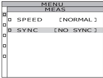
The MENU - MEAS screen appears.
The current set contents are displayed in the SYNC item.
3. Press either or key to select [SYNC] and then press ENTER key.
The MENU - MEAS - SYNC MODE (sync method selection) screen appears.
4. Press either or key to select the sync method.
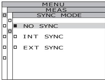
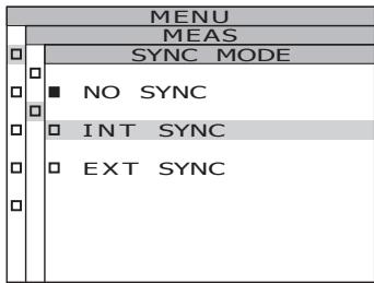
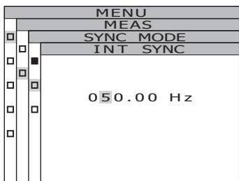
4-a-1. INT SYNC setting: Select [INT SYNC] and press ENTER key.
The MENU - MEAS - SYNC MODE - INT SYNC screen appears. This screen is used for the input of an internal synchronized frequency.
![KONICA CS-2000 - 4-a-1. INT SYNC setting: Select [INT SYNC] and press ENTER key. - 1](/content/2025/01/172147/images/3bc7dd9c85f2ac0bba86547596f7ec3ebf9f696a3495b06058ef565c38fa120a.jpg)
4-a-2. Press either or key to set a value.
key for larger number.
key for smaller number.
The range of the internal synchronized frequency is from 20Hz to 200Hz .
4-a-3. Press either or key to move the cursor.
4-a-4. Repeat the same procedures 4-a-2. and -3. as necessary.
4-a-5. Press ENTER key.
After the setting is entered, the MENU - MEAS - SYNC MODE screen appears again on the LCD.
5. Press ENTER key.
When the synchronizing method is set, the MENU - MEAS screen appears again on the LCD.
By pressing ESC key, after the setting is canceled the MENU - MEAS screen appears again on the LCD.
The setting of the synchronizing method is saved even after the power switch is turned off (O).
6. Press ENTER key.
The MENU screen appears again on the LCD.
7. Press ESC key.
The MEAS screen appears again on the LCD.
Selecting Measurement Time
Select measurement time according to the purpose. Four modes are available for measurement time.
| NORMAL | Mode is used when repeat accuracy is required, for example when measuring objects with low luminance. |
| FAST | Mode is used when the shorter measurement time has priority. |
| MULTI INTEG | Mode is used when [NO SYNC] is set for the synchronizing method if the sync cycle is not clear. This mode is also used to reduce the measurement variation when the sync cycle is unstable, even if it is clear. |
| MANUAL | Mode is used to fix the conditions by inputting the integral action time*1 manually, like the case where an object susceptible to measurement conditions is measured. |
1 Time for sensor to measure light indicating "exposure time". On the other hand, measurement time shows time for integration × 2 + Time to open/close shutter + Time for calculation), indicating time needed for actual measurement.
Factory default setting : MULTI INTEG, 1s
Operation Procedure
1. Press MENU key when the MEAS screen is displayed.
The MENU screen appears.
When the backlight of the LCD has been turned off via BACKLIGHT key on the MEAS screen, the backlight is turned on.
2. Press either or key to select [MEAS] and then press ENTER key.
The MENU - MEAS screen appears.
The current set contents are displayed in the SPEED item.
![KONICA CS-2000 - Press either or key to select [MEAS] and then press ENTER key. - 1](/content/2025/01/172147/images/0a842af305b20aae57d0ddb1fbec2d98971fb49444042e8e427b9023910a3146.jpg)
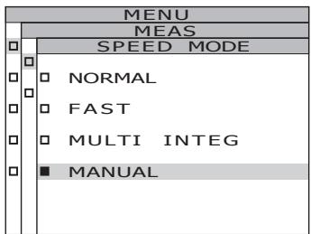
- Press either or key to select [SPEED] and then press ENTER key. The MENU - MEAS - SPEED MODE (measurement speed setting) screen appears.
- Press either or key to select measurement speed.
![KONICA CS-2000 - Press either or key to select [MEAS] and then press ENTER key. - 2](/content/2025/01/172147/images/74a8ca8cb0cce8a6b122e9d4f0515bba1af9e62a18fddc4da684314b7b90a013.jpg)
![KONICA CS-2000 - Press either or key to select [MEAS] and then press ENTER key. - 3](/content/2025/01/172147/images/b6c0a6978a97672ec45eabfee8abe7cecb8fa7745a727bb602aa5de7604cdaa4.jpg)
4-a-1. MULTI INTEG setting: Select [MULTI INTEG] and press ENTER key.
The MENU - MEAS - SPEED MODE - MULTI INTEG screen appears.
This screen is used for input of the measured integral action time in the MULTI INTEG mode.
![KONICA CS-2000 - Press either or key to select [MEAS] and then press ENTER key. - 4](/content/2025/01/172147/images/a93360b10eb96e1e634aea1ec3500214595b6880727933ab088f8784b2acf5b5.jpg)
4-a-2. Press either or key to set a value.
key for larger number.
key for smaller number.
The setting range of integral action time is from 1 to 16 s.
![KONICA CS-2000 - Press either or key to select [MEAS] and then press ENTER key. - 5](/content/2025/01/172147/images/12b61a10ab0682be5663034c5e371e6849dcf3bf903161754920157f0a4f7eb4.jpg)
4-a-3. Press ENTER key. After the setting is entered, the MENU - MEAS - SPEED MODE screen appears again on the LCD.
![KONICA CS-2000 - Press either or key to select [MEAS] and then press ENTER key. - 6](/content/2025/01/172147/images/cc122c087ec6d1766279c93da24cfbf9542ba461dba2fb936c593c6ec3d76ecc.jpg)
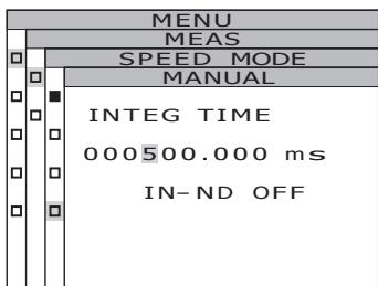
4-b-1. MANUAL setting: Select [MANUAL] and press ENTER key.
The MENU - MEAS - SPEED MODE - MANUAL screen appears. This screen is used for input of the measured integral action time in the manual mode.
![KONICA CS-2000 - 4-b-1. MANUAL setting: Select [MANUAL] and press ENTER key. - 1](/content/2025/01/172147/images/ae6f8a5cca76270a8f37222540928f9af6a0aedf55880ecae6d22c593522f248.jpg)
![KONICA CS-2000 - 4-b-1. MANUAL setting: Select [MANUAL] and press ENTER key. - 2](/content/2025/01/172147/images/c8e9d01a313c9298da07e16326a7bb00240b73b5789352f0880d434097450010.jpg)
4-b-2. Press either or key to set a value.
key for larger number.
key for smaller number.
The setting range of integral action time is from 5 to 120,000 ms.
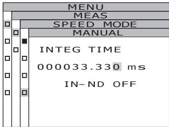
4-b-3. Press either or key to move the cursor.
4-b-4. Repeat the same procedures 4-a-2. and -3. as necessary.
4-b-5. Press ENTER key.
The cursor moves to the IN-ND item.
This screen is used to determine whether the ND filter built into the body is used or not.
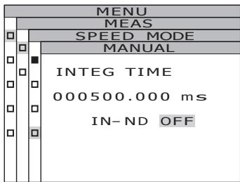
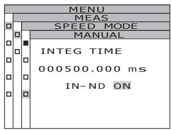
4-b-6. Press either or key to select [ON] or [OFF].
Select [ON] when the error message, OVER appears.
4-b-7. Press ENTER key.
When the setting is entered, the MENU - MEAS - SPEED MODE screen appears again on the LCD.
5. Press ENTER key.
When the measurement time is set, the MENU - MEAS screen appears again on the LCD.
By pressing ESC key, after the setting is canceled the MENU - MEAS screen appears again on the LCD.
Measurement time setting is saved even after switching OFF (O).
6. Press ESC key.
The MENU screen appears again on the LCD.
7. Press ESC key.
The MEAS screen appears again on the LCD.
Color matching function for chromaticity calculation is selectable between 2^ OBS and 10^ OBS.
- Observer setting : 2°OBS, 10°OBS
- Factory default setting : 2°OBS
Operation Procedure
1. Press MENU key when the MEAS screen is displayed.
The MENU screen appears.
When the backlight of the LCD has been turned off via BACKLIGHT key on the MEAS screen, the backlight is turned on.
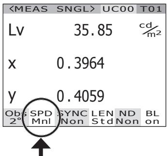
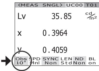
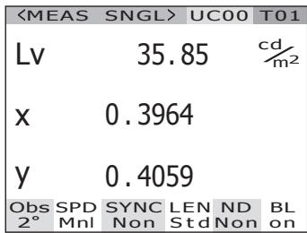
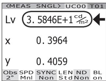
| <MEAS | SNGL> | UC00 | T01 | ||
| Lv | 35.85 | cd/m2 | |||
| x | 0.3964 | ||||
| y | 0.4059 | ||||
| Obs | SPD | SYNC | LEN | ND | BL |
| 2° | Mnl | Non | Std | Non | on |
2. Press either or key to select [SETUP] and then press ENTER key.
The MENU - SETUP screen appears.
The current set contents are displayed in the [OBSERVER] item.
| MENU |
| □ MEAS |
| □ MEMORY |
| □ TARGET |
| □ OPTION |
| □ SETUP |
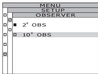
3. Press either or key to select [OBSERVER] and then press ENTER key.
The MENU - SETUP - OBSERVER (Observer selection) screen appears.
| MENU | |
| SETUP | |
| OBSERVER | [2°] |
| BACKLIGHT@MEAS ON | |
| DATA FORM | [F] |
| MENU | |
| SETUP | |
| OBSERVER | |
| 2° OBS | |
| 10° OBS |
4. Press either or key to select [2^ OBS] or [10^ OBS] .
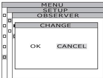
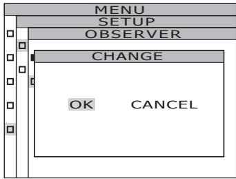
5. Press ENTER key.
The confirmation screen appears. [CANCEL] is selected.
6. Press key to move the cursor to [OK].
7. Press ENTER key.
When the observer angle is set, the MENU - MEAS screen appears again on the LCD.
By pressing ESC key, after the setting is canceled the MENU - SETUP screen appears again on the LCD.
Observer setting is saved even after switching OFF (O).
8. Press ESC key.
The MENU screen appears again on the LCD.
9. Press ESC key.
The MEAS screen appears again on the LCD. When observer angle is set to 10^ , L_V display changes to Y display.
Selecting Display Format
The formats of indicating the luminance and excitation values X, Y and Z can be selected as either normal indication to display the values to four places of decimals, or as index number indication. If the measurement values on the LCD are unreadable, use the index number indication.
- Display format setting : Normal, Index
- Factory default setting : .* [F]
Operation Procedure
1. Press MENU key when the MEAS screen is displayed.
The MENU screen appears.
When the backlight of the LCD has been turned off via BACKLIGHT key on the MEAS screen, the backlight is turned on.
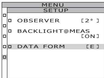
2. Press either or key to select [SETUP] and then press ENTER key.
The MENU - SETUP screen appears.
The current set contents are displayed in the [DATA FORM] item.
![KONICA CS-2000 - Press either or key to select [SETUP] and then press ENTER key. - 1](/content/2025/01/172147/images/16d1d5995552b3d44198678bef7f9eba5e5d3439c56aac45473f3198c56d2f2d.jpg)
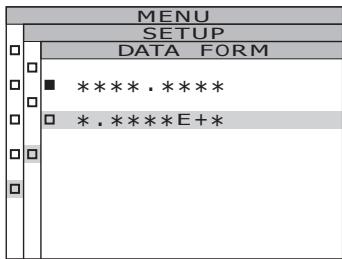
3. Press either or key to select [DATA FORM] and then press ENTER key.
The MENU - SETUP - DATA FORM (Display format selection) screen appears.
![KONICA CS-2000 - Press either or key to select [DATA FORM] and then press ENTER key. - 1](/content/2025/01/172147/images/662d91172660082f031fd69e29eb066dc303d5cad546c99bd8e7d90d02e375d5.jpg)
4. Press either or key to select [****.**** [F]] or [*.****E+ [E]].
5. Press ENTER key.
When the display format is set, the MENU - SETUP screen appears again on the LCD.
By pressing ESC key, after the setting is canceled the MENU - SETUP screen appears again on the LCD.
Display format setting is saved even after switching OFF (O).
6. Press ESC key.
The MENU screen appears again on the LCD.
7. Press ESC key.
The MEAS screen appears again on the LCD.
Selecting Color Space
See below table for available color space.
- Factory default setting :Lvxy
| Color Space | LCD Screen | Display Description | |
| (When Normal is selected for display format) | (When Index is selected for display format) | ||
| Lxy *1 | <MEAS SNGL>UC00 TO1Lv 34.22 cd/m2x 0.3958y 0.4060Obs SPD SYNC LEN ND BL2° Nrm Non StdNon on | <MEAS SNGL>UC00 TO1Lv 3.4221E+1 cd/m2x 0.3958y 0.4060Obs SPD SYNC LEN ND BL2° Nrm Non StdNon on | Displays and outputs in luminance Lv and chromaticity coordinates x,y. |
| Lv u'v' *1 | <MEAS SNGL>UC00 TO1Lv 34.22 cd/m2u' 0.2236v' 0.5161Obs SPD SYNC LEN ND BL2° Nrm Non StdNon on | <MEAS SNGL>UC00 TO1Lv 3.4221E+1 cd/m2u' 0.2236v' 0.5161Obs SPD SYNC LEN ND BL2° Nrm Non StdNon on | Displays and outputs in luminance Lv and u'v' chromaticity diagram (CIE 1976 UCS chromaticity diagram) coordinates u', v'. |
| Lv T Δuv | <MEAS SNGL>UC00 TO1Lv 34.22 cd/m2T 3829Kduv +0.009Obs SPD SYNC LEN ND BL2° Nrm Non StdNon on | <MEAS SNGL>UC00 TO1Lv 3.4221E+1 cd/m2T 3829Kduv +0.009Obs SPD SYNC LEN ND BL2° Nrm Non StdNon on | Displays and outputs in luminance Lv, correlated color temperature T and color difference from blackbody locus Δuv. |
| XYZ | <MEAS SNGL>UC00 TO1X 33.36Y 34.22Z 16.71Obs SPD SYNC LEN ND BL2° Nrm Non StdNon on | <MEAS SNGL>UC00 TO1X 3.3365E+1Y 3.4221E+1Z 1.6709E+1Obs SPD SYNC LEN ND BL2° Nrm Non StdNon on | Displays and outputs in tristimulus values X, Y, Z. |
| Dominant wavelength/Excitation purity *2 | <MEAS SNGL>UC00 TO1λd +576.220nmPe 0.407Obs SPD SYNC LEN ND BL2° Nrm Non StdNon on | Displays and outputs in dominant wavelength λd and excitation purity Pe. | |
| Spectral graph | <MEAS SNGL>UC00 TO1380 <380nm >7801.3118E-5Obs SPD SYNC LEN ND BL2° Nrm Non StdNon on | Displays or outputs spectral radiance Le(λ) in the spectral waveform | |
1 Y is displayed instead of L_v when observer angle is 10^ .
2 For non-spectral colors, the complementary wavelength will be displayed. The display indication will remain λd.
Operation Procedure
1. When the MENU or MEMORY screen is displayed, press ESC key to switch to the MEAS screen.
2. Press COLOR MODE key to display the desired color space.
Measurement screen switches in order of L_vxy L_vu'v' L_vT uv XYZ d / Pe Spectral graph L_vxy while COLOR MODE key is pressed.
It switches in order of Yxy Yu' v' XYZ d/Pe Spectral~graph Yxy when observer angle is 10^ .
Color space setting is saved even after switching OFF (O).
| <MEAS | SNGL> | UC00 | T01 | |
| Lv | 34.22 | cd/m2 | ||
| X | 0.3958 | |||
| Y | 0.4060 | |||
| Obs | SPD | SYNC | LEN | ND |
| 2° | Nrm | Non | Std | Non |
| <MEAS | SNGL> | UC00 | T01 | |
| Lv | 34.22 | cd/m2 | ||
| u' | 0.2236 | |||
| v' | 0.5161 | |||
| Obs | SPD | SYNC | LEN | ND |
| 2° | Nrm | Non | Std | Non |
Selecting Absolute Value (ABS)/Difference (DIFF) Display
Whether chromaticity value is shown in absolute (ABS) or difference (DIFF) is selectable. See below table for each case.
- Factory default setting: Absolute value (ABS)
| Color Space | Absolute value (ABS) | Difference (DIFF) |
| Lvxy *1 | Lv, x, y | Lv, x, y ΔLv, %Lv, Δx, Δy |
| <MEAS SNGL> UC00 T01 | <MEAS SNGL> UC00 T01 | |
| Lv 34.22 cd/m2 | Lv 34.34 cd/m2x 0.3958y 0.4059 | |
| x 0.3958 | x 0.3958y 0.4059 | |
| y 0.4060 | y 0.4059 | |
| Obs SPD SYNC LEN ND BL2° Nrm Non StdNon on | Obs SPD SYNC LEN ND BL2° Nrm Non StdNon on | |
| Lv u'v' *1 | Lv, u', v' | Lv, u', v' |
| <MEAS SNGL> UC00 T01 | <MEAS SNGL> UC00 T01 | |
| Lv 34.22 cd/m2 | Lv 34.34 cd/m2u' 0.2236v' 0.5160 | |
| u' 0.2236 | u' 0.2236v' 0.5160 | |
| v' 0.5161 | v' 0.5161 | |
| Obs SPD SYNC LEN ND BL2° Nrm Non StdNon on | Obs SPD SYNC LEN ND BL2° Nrm Non StdNon on | |
| Lv T Δuv | Lv, T, duv | Lv, T, duv |
| <MEAS SNGL> UC00 T01 | <MEAS SNGL> UC00 T01 | |
| Lv 34.22 cd/m2 | Lv 34.34 cd/m2T 3830k duv + 0.009 | |
| T 3829K | T 3830k duv + 0.1188 | |
| duv +0.009 | duv +0.1188cd/m2%Lv 100.35%OK | |
| Obs SPD SYNC LEN ND BL2° Nrm Non StdNon on | Obs SPD SYNC LEN ND BL2° Nrm Non StdNon on | |
| XYZ | X, Y, Z | X, Y, Z |
| <MEAS SNGL> UC00 T01 | ΔX, ΔY, ΔZ%X, %Y, %Z | |
| X 33.36 | <MEAS SNGL> UC00 T01 | |
| Y 34.22 | X 33.49 | |
| Z 16.71 | Y 34.34 | |
| Obs SPD SYNC LEN ND BL2° Nrm Non StdNon on | Z 16.78 | |
| Obs SPD SYNC LEN ND BL2° Nrm Non StdNon on | ΔX +0.1204 | |
| Obs SPD SYNC LEN ND BL2° Nrm Non StdNon on | ΔY +0.1188 | |
| Obs SPD SYNC LEN ND BL2° Nrm Non StdNon on | ΔZ +0.07479 | |
| Obs SPD SYNC LEN ND BL2° Nrm Non StdNon on | ΔX% 100.36% | |
| Obs SPD SYNC LEN ND BL2° Nrm Non StdNon on | ΔY% 100.35% | |
| Obs SPD SYNC LEN ND BL2° Nrm Non StdNon on | ΔZ% 100.45% | |
| Obs SPD SYNC LEN ND BL2° Nrm Non StdNon on | Obs SPD SYNC LEN ND BL2° Nrm Non StdNon on | |
| Dominant wavelength | λd, Pe | λd·Pe |
| <MEAS SNGL> UC00 T01 | <MEAS SNGL> UC00 T01 | |
| λd +576.220nm | λd +576.220nm | |
| Pe 0.407 | Fe 0.406 | |
| Obs SPD SYNC LEN ND BL2° Nrm Non StdNon on | Δλd 0.000nm | |
| Obs SPD SYNC LEN ND BL2° Nrm Non StdNon on | ΔPe -0.000 | |
| Obs SPD SYNC LEN ND BL2° Nrm Non StdNon on | Obs SPD SYNC LEN ND BL2° Nrm Non StdNon on | |
| Spectral graph | Le (λ) spectral waveform Wavelength at the cursor position and Le (λ) in the wavelength | Measurement value and Le (λ) spectral waveform of target color Wavelength of the cursor position and Le (λ) of the measurement value in the wavelength |
| <MEAS SNGL>UC00 T01 380←380nm→780 1.3118E-5 Obs SPD SYNC LEN ND BL 2° Nrm Non StdNon on | <MEAS SNGL>UC00 T01 380←380nm→780 4+1.8704E-7 Obs SPD SYNC LEN ND BL 2° Nrm Non StdNon on |
1 Y is displayed instead of L_v when observer angle is 10^ .
2 Even if either the measured value, target color, or both are the complementary wavelength, the difference between the two values will be displayed. The display indication will remain d .
Operation Procedure
1. When the MENU or MEMORY screen is displayed, press ESC key to switch to the MEAS screen.
2. Press DISPLAY key to show absolute value (ABS) or color difference (DIFF) to select.
Measurement value switches between that for absolute value (ABS) and difference (DIFF) while DISPLAY key is pressed.
The setting of absolute value (ABS) and difference (DIFF) is saved even after switching OFF (O).
| <MEAS | SNGL> | UC00 | T01 | |
| Lv | 34.22 | cd/m2 | ||
| X | 0.3958 | |||
| Y | 0.4060 | |||
| Obs | SPD | SYNC | LEN | ND |
| 2° | Nrm | Non | Std | Non |
| <MEAS | SNGL> | UC00 | T01 | ||
| Lv | 34.34 | cdr2m2 | |||
| x | 0.3958 | ||||
| y | 0.4059 | ||||
| ΔLv | +0.1188 | cdr2m2 | |||
| %Lv | 100.35% | ||||
| Δx. | -0.0000 | ||||
| Δy. | -0.0001 | ||||
| Obs | SPD | SYNC | LEN | ND | BL |
| 2° | Nrm | Non | Std | Non | on |
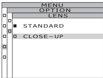
When Using Closeup Lens
Use the closeup lens in the optional accessories to measure a fine surface. For the attachment of the closeup lens, refer to the instruction manual for the closeup lens.
If the closeup lens is attached, the measurement value must be compensated for the lens transmittance. This compensation coefficient is attached to the closeup lens. Use the data management software CS-S10w Professional supplied with the CS-2000 as standard to set the coefficient in this instrument. After that, when the closeup lens is selected as lens type, the measurement value compensated with the compensation coefficient can be obtained. See instruction manual of CS-S10w for details.
The wrong setting of lens type leads to inaccurate measurement.
Do not use the closeup lens with the ND filter. It leads to inaccurate measurement.
-
Lens type : STANDARD, CLOSE-UP
-
Factory default setting : STANDARD
Operation Procedure

1. Press MENU key when the MEAS screen is displayed.
The MENU screen appears.
When the backlight of the LCD has been turned off via BACKLIGHT key on the MEAS screen, the backlight is turned on.
2. Press either or key to select [OPTION] and then press ENTER key.
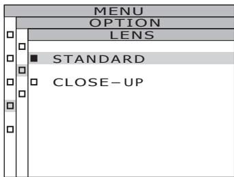
The MENU - OPTION screen appears. The current set contents are displayed in the [LENS] item.
![KONICA CS-2000 - Press either or key to select [OPTION] and then press ENTER key. - 1](/content/2025/01/172147/images/a8d4db25361d16a5d7740a9ecebf3a6c556ef3dde6214edecfb14e60743a6597.jpg)
![KONICA CS-2000 - Press either or key to select [OPTION] and then press ENTER key. - 2](/content/2025/01/172147/images/cfe7fffa6b40419e85b81d9ef30bfffe22184fb42a4680d2ac2e1d43ec593a7e.jpg)
3. Press either or key to select [LENS] and then press ENTER key.
The MENU - SETUP - LENS (Lens type selection) screen appears.
4. Press either or key to select [CLOSE-UP].
When you removed the closeup lens, select [STANDARD].
5. Press ENTER key.
When the lens type is set, the MENU - OPTION screen appears again on the LCD.
By pressing ESC key, after the setting is canceled the MENU - OPTION screen appears again on the LCD.
Lens type setting is saved even after switching OFF (O).
6. Press ESC key.
The MENU screen appears again on the LCD.
7. Press ESC key.
The MEAS screen appears again on the LCD.
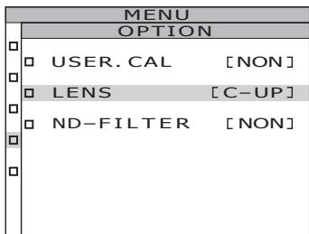
Use the ND filter in the optional accessories when measuring a high-luminance object. If the ND filter is attached, the measurement value must be compensated for the filter transmittance. This compensation coefficient is attached to the ND filter. Use the data management software CS-S10w Professional supplied with the CS-2000 as standard to set the coefficient in this instrument. After that, when the ND filter is selected as lens type, the measurement value compensated with the compensation coefficient can be obtained. See instruction manual of CS-S10w for details.
The wrong setting of ND filter leads to inaccurate measurement.
Do not use the ND filter with the closeup lens. It leads to inaccurate measurement.
Note that an extra ND filter is built into this instrument. The use or non-use of this built-in ND filter is switched automatically, depending on the luminance of the object.
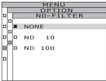
-
ND-FILTER : NONE, ND10, ND100
-
Factory default setting: NONE
Operation Procedure
1. Press MENU key when the MEAS screen is displayed.
The MENU screen appears.
When the backlight of the LCD has been turned off via BACKLIGHT key on the MEAS screen, the backlight is turned on.
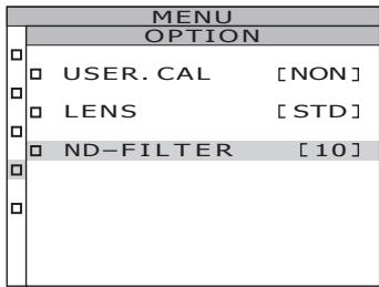
2. Press either or key to select [OPTION] and then press ENTER key.
The MENU - OPTION screen appears.
The current set contents are displayed in the [ND-FILTER] item.
![KONICA CS-2000 - Press either or key to select [OPTION] and then press ENTER key. - 1](/content/2025/01/172147/images/c1223a100a680792b156a96d1f0a8b2185fca698bae26c8aa8d4a5bbb9ebae0b.jpg)
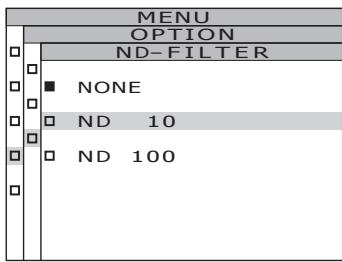
3. Press either or key to select [ND-FILTER] and then press ENTER key.
The MENU - SETUP - ND-FILTER (ND filter selection) screen appears.
4. Press either or key to select [NONE], [ND 10] or [ND 100].
5. Press ENTER key.
When the ND filter is set, the MENU - OPTION screen appears again on the LCD.
By pressing ESC key, after the setting is canceled the MENU - OPTION screen appears again on the LCD.
ND filter setting is saved even after switching OFF (O).
6. Press ESC key.
The MENU screen appears again on the LCD.
7. Press ESC key.
The MEAS screen appears again on the LCD.
Calibration Channel
This instrument includes 11 calibration channels from Ch00 to Ch10.
Ch00 is for measurement based upon KONICA MINOLTA SENSING's calibration standard. Its calibration correction coefficient has been set and is unchangeable.
The following contents can be set to Ch01 to Ch10 respectively using data management software CS-S10w Professional supplied with the CS-2000 as standard. See instruction manual of CS-S10w for details.
- Correction coefficient of user calibration
- Correction coefficient ID
They are commonly used among each color space of L_ , L_'v' , L_ uv , XYZ , dominant wavelength/excitation purity and spectral graph in one channel.
Calibration channels can be changed using the following procedure.
Operation Procedure
1. Press MENU key when the MEAS screen is displayed.
The MENU screen appears.
When the backlight of the LCD has been turned off via BACKLIGHT key on the MEAS screen, the backlight is turned on.

2. Press either or key to select [OPTION] and then press ENTER key.
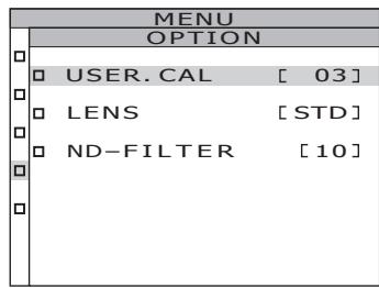
The MENU - OPTION screen appears.
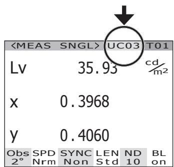
The current set contents are displayed in the [USER.CAL] item.
![KONICA CS-2000 - Press either or key to select [OPTION] and then press ENTER key. - 1](/content/2025/01/172147/images/a1e01dd1e22717e7c4488eb21b4d373691f598843257a175b3f64e294b91f54f.jpg)
3. Press either or key to select [USER.CAL] and then press ENTER key.
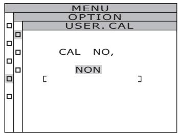
The MENU - SETUP - USER.CAL (Calibration channel selection) screen appears.
The calibration channel number and compensation coefficient ID (with a maximum of 10 letters) are displayed. In case of Ch00, "NON" is displayed. See instruction manual of CS-S10w for details.
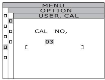
4. Press either or key to select the channel.
key for larger number.
key for smaller number.
The calibration channel numbers can be selected among NON, and 01 to 10.
5. Press ENTER key.
When the calibration channel is set, the MENU -OPTION screen appears again on the LCD.
If the calibration channel without compensation coefficient setting is selected, the setting will not be possible.
By pressing ESC key, after the setting is canceled the MENU - OPTION screen appears again on the LCD.
6. Press ESC key.
The MENU screen appears again on the LCD.
7. Press ESC key.
The MEAS screen appears again on the LCD.
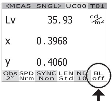
Backlight ON/OFF During Measurement
The LCD backlight can be selectively turned on or off during measurement.
If the backlight is turned off, LCD backlight reflection on the surrounding area
affecting the measurement value during measurement can be avoided.
If pressing the BACKLIGHT key to turn off the backlight, while the MEAS screen is
displayed, the backlight is forcibly turned off independently of the following setting.
- Factory default setting : ON
Operation Procedure

1. Press MENU key when the MEAS screen is displayed.
The MENU screen appears.
When the backlight of the LCD has been turned off via BACKLIGHT key on the MEAS screen, the backlight is turned on.
2. Press either or key to select [SETUP] and then press ENTER key.
The MENU - SETUP screen appears.
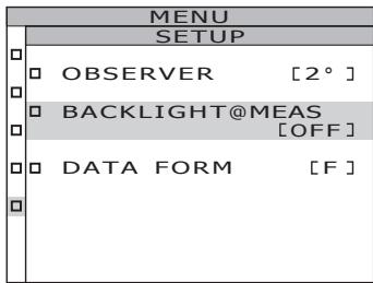
The current set contents are displayed in the [BACKLIGHT@MEAS] item.
![KONICA CS-2000 - Press either or key to select [SETUP] and then press ENTER key. - 1](/content/2025/01/172147/images/66c4603e0d2d3f804aeb419c5b517fa78b0743ae4dfba228d646d467e9fa5f16.jpg)
![KONICA CS-2000 - Press either or key to select [SETUP] and then press ENTER key. - 2](/content/2025/01/172147/images/76d2c181d70caed54c822e0a30848298401f534c860f6c564017b7e190fd547d.jpg)
3. Press either or key to select [BACKLIGHT@MEAS] and then press ENTER key.
The MENU - SETUP - BACKLIGHT@MEAS (Turning ON/OFF backlight during measurement) screen appears on the LCD.
4. Press either or key to select [ON] or [OFF].
![KONICA CS-2000 - Press either or key to select [ON] or [OFF]. - 1](/content/2025/01/172147/images/0d7364cbce38447f30afb09403e1cf912a7d8902d3643de725df451bc0be406f.jpg)
5. Press ENTER key.
When the setting is made to turn the backlight on or off during measurement, the MENU - SETUP screen appears again on the LCD.
By pressing ESC key, after the setting is canceled the MENU - SETUP screen appears again on the LCD.
Setting of backlight ON/OFF during measurement is saved even after switching OFF (O).
6. Press ENTER key.
The MENU screen appears again on the LCD.
7. Press ESC key.
The MEAS screen appears again on the LCD.
Measurement
Operation Procedure
1. Decide whether you use closeup lens (optional accessory) or not according to measuring object size and distance.
See the table below for details on measuring distance and measuring area. If you set the closeup lens, lens type setting is required in this instrument. (See p.42)
(Unit: mm)
Measuring distance and measuring area
| Minimum measurement diameterø | Maximum measurement diameterø | Minimum measurement area | Maximum measurement area | Measuring area when the measuring distance is 500 mmø | Measuring area when the measuring distance is 1,000 mmø | |||||||||||||
| (Measuring angle) | 1° | 0.2° | 0.1° | 1° | 0.2° | 0.1° | 1° | 0.2° | 0.1° | 1° | 0.2° | 0.1° | 1° | 0.2° | 0.1° | 1° | 0.2° | 0.1° |
| Without closeup lens | 5.00 | 1.00 | 0.50 | ∞ | ∞ | ∞ | 350 | ∞ | 7.78 | 1.56 | 0.78 | 16.66 | 3.33 | 1.67 | ||||
| With closeup lens | 1.00 | 0.20 | 0.10 | 1.39 | 0.28 | 0.14 | 55.0 | 70.9 | - | - | - | - | - | - | ||||
*Measurement distance is the distance from the front edge of the metal lens barrel or closeup lens ring.
2. Rotate the measuring angle selector according to size of object and measurement distance, and set the aperture to 1^ , 0.2^ , or 0.1^ .
Do not operate the measuring angle selector during measurement. If measuring angle is switched during measurement, you may fail to perform measurement or to obtain correct measurement value. To rotate the measuring angle selector, move to a position where you can confirm the click. If you stop the selector in a halfway position, measurement may not be performed or wrong measurement values may be obtained.
3. Rotate the diopter adjustment ring for adjustment of diopter.
Make sure that aperture (black circle indicating measurement area) looks clear when observing object through finder. (See p.15)
4. Rotate the focus adjustment ring for objective lens for that purpose.
Make sure that object around aperture looks clear when observing object through finder. Only measuring area for measuring object must be placed in aperture. If extra area, which is not measuring object, is included in aperture, you cannot perform correct measurement.
5. When the MENU or MEMORY screen is displayed, press ESC key to switch to the MEAS screen.
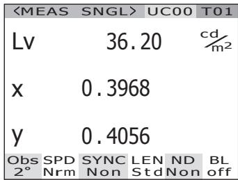
The MEAS (Measurement value) screen appears.
6. Press the measurement button.
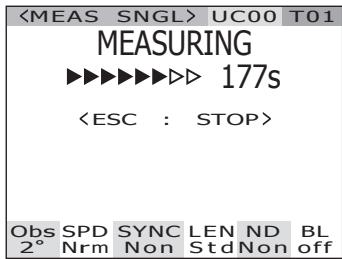
When the measurement time is long, the measurement progress bar is displayed on the LCD until measurement is complete.
If the measurement time is set to options other than [Manual], the measurement time will be determined after the approximate luminance is checked inside the measurement device. For this reason, it may take several seconds until the measurement time appears. The displayed time shows approximately how long it will take from the point of time display to the end of measurement.
If the measurement time is set to options other than [Manual], the remaining time, which is 16 seconds or less, will not be displayed. With [Manual] as the setting, the remaining time, which is 8 seconds or less, will not be displayed.
Display during measurement (Single measurement/when measurement time is long)
(Single measurement/when measurement time is short)
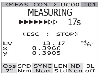
When the measuring button is pressed and held for two or more seconds, continuous measurement is conducted.
When the measurement time is long, the measurement progress bar appears with the latest measurement value. The displayed time shows the remaining time, same as for the single measurement.
When the measurement time is short, the measurement progress bar does not appear, but the measurement value is sequentially updated and displayed.
When the measurement button is pressed during continuous measurement, continuous measurement will be stopped after the current measurement ends. The last result during continuous measurement is displayed on the LCD.
When ESC key is pressed, measurement is stopped. In this case, the last measurement value will be cleared.
Display during measurement (Continuous measurement/when measurement time is long)
(Continuous measurement/when measurement time is short)
When ENTER key is pressed while the measurement value is displayed, the measurement properties are displayed so that the measurement conditions can be confirmed. When the measuring button or a random key is pressed, the MEAS screen appears again.
PROPERTIES
ANGLE 1. 0^
SPEED NORMAL
SYNC NO SYNC
LENS STANDARD
FILTER NONE
IN-ND OFF
INTG 66.667ms
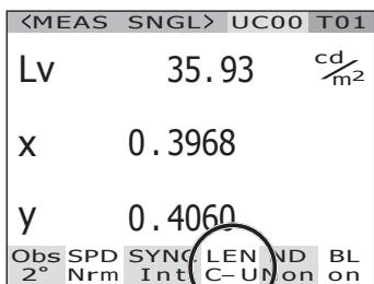
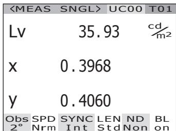
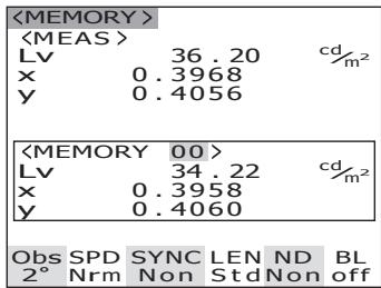
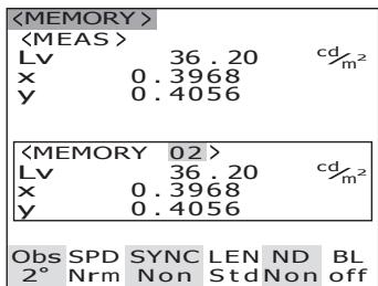
Saving the Measurement Value
This instrument can save 100 measurement values with designated numbers from 00 to 99.
Operation Procedure
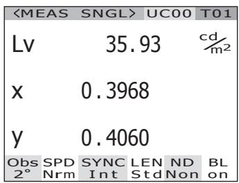
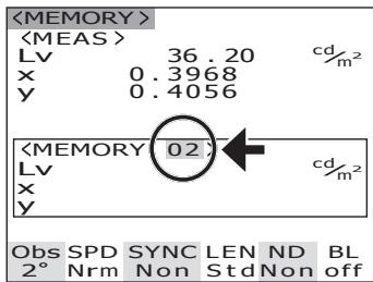
1. When the MEAS screen is displayed, press key to switch to the MEMORY screen.
The MEMORY (Memory data) screen appears. The memory data number oo is displayed.
2. Press either or key to select the number of memory data.
key for larger number.
key for smaller number.
3. Press ENTER key.
Each measurement value is saved with the selected number.
If ESC key is pressed, saving is canceled and the MEAS screen appears on the LCD.
Use the following procedure to display the memory data properties (measurement conditions):
Operation Procedure
1. Press MENU key when the MEAS screen is displayed.
The MENU screen appears.
When the backlight of the LCD has been turned off via BACKLIGHT key on the MEAS screen, the backlight is turned on.
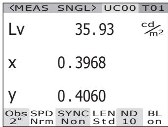
| <MEAS SNGL> | UC00 | T01 | |
| Lv | 35.93 | cd/m2 | |
| x | 0.3968 | ||
| y | 0.4060 | ||
| Obs | SPD | SYNC | LEN |
| 2° | Nrm | Non | Std Non |
2. Press either or key to select [MEMORY] and then press ENTER key.
The MENU - MEMORY screen appears.
| MENU |
| MEAS |
| MEMORY |
| TARGET |
| OPTION |
| SETUP |
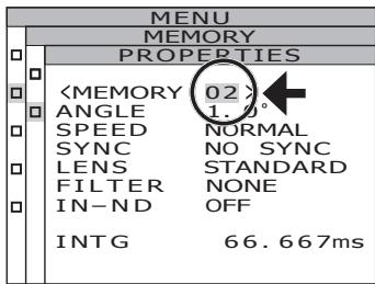
3. Press either or key to select [PROPERTIES] and then press ENTER key.
The MENU - MEMORY - PROPERTIES (Memory data measurement condition confirmation) screen appears.
The memory data number 00 is displayed.
| MENU | |
| MEMORY | |
| DELETE | |
| PROPERTIES |
| MENU | |
| MEMORY | |
| PROPERTIES | |
| <MEMORY 00> | |
| ANGLE 1.0° | |
| SPEED NORMAL | |
| SYNC NO SYNC | |
| LENS STANDARD | |
| FILTER NONE | |
| IN-ND OFF | |
| INTG 66.667ms |
4. To display the memory data for another number, press either or key to change the memory data number.
The properties of the selected memory data are displayed, and the measurement conditions can be confirmed.
key for larger number.
If kept pressed, the value continuously changes.
key for smaller number.
If kept pressed, the value continuously changes.
5. Press ESC key.
The MENU - MEMORY screen appears again on the LCD.
6. Press ESC key.
The MEAS screen appears again on the LCD.
Deleting the Memory Data
Stored measurement values can be deleted in the following procedure.
Operation Procedure

1. Press MENU key when the MEAS screen is displayed.
The MENU screen appears.
When the backlight of the LCD has been turned off via BACKLIGHT key on the MEAS screen, the backlight is turned on.
| <MEAS SNGL> | UC00 | T01 | |
| Lv | 35.93 | cd/m2 | |
| x | 0.3968 | ||
| y | 0.4060 | ||
| Obs | SPD | SYNC | LEN |
| 2° | Nrm | Non | Std Non |
| MENU |
| MEAS |
| MEMORY |
| TARGET |
| OPTION |
| SETUP |
2. Press either or key to select [MEMORY] and then press ENTER key.
The MENU - MEMORY screen appears.
| MENU | |
| MEMORY | |
| DELETE | |
| PROPERTIES |
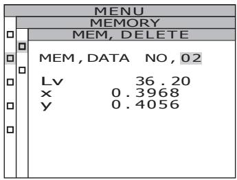
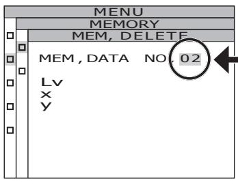
3. Press either or key to select [DELETE] and then press ENTER key.
The MENU - MEMORY - DELETE (Memory data deletion) screen appears.
The memory data number 00 is displayed.
| MENU | |
| MEMORY | |
| MEM, DELETE | |
| MEM, DATA NO, 00 | |
| Lv | 34.22 |
| x | 0.3958 |
| y | 0.4060 |
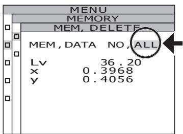
4. Press either or key to select the number of memory data you want to delete.
key for larger number. If kept pressed, the value continuously changes. [ALL] is displayed after No.99.
key for smaller number. If kept pressed, the value continuously changes. [ALL] is displayed after No.00.
The deleted memory data can not be recovered. Confirm the number before deleting the memory data.
5-a-1. Deletion of saved data, one by one: Select the number of the memory data to be deleted, and press ENTER key.
The saved measurement value disappears. By pressing ESC key, the deletion of the memory data is canceled and the MENU - MEMORY screen appears again on the LCD.
5-a-2. Repeat the steps 4 through 5-a-1. as necessary.
5-a-3. Press ESC key.
The MENU - MEMORY screen appears again on the LCD.
5-b-1. Collective deletion of all memory data:
Select [ALL] and press ENTER key.
The confirmation screen for deletion of all memory data is displayed.
5-b-2. Press key to select [OK] and then press ENTER key.
All memory data are deleted, and the MENU - MEMORY screen appears again on the LCD. By selecting [CANCEL] and pressing ESC key, or pressing ENTER key, the deletion of all memory data is canceled and the MENU - MEMORY screen appears again on the LCD.
![KONICA CS-2000 - 5-b-2. Press key to select [OK] and then press ENTER key. - 1](/content/2025/01/172147/images/fff60fde1cc9e6026620cc4e102c525c02a16d0eaba960f9bd1bd6b18721b69a.jpg)
6. Press ESC key.
The MENU - MEMORY screen appears again on the LCD.
7. Press ESC key.
The MEAS screen appears again on the LCD.
Target color
The target color serves as reference for measurement of deviation of measured color from reference.
Target colors can be registered up to 20 from Ch 01 to Ch 20 completely within this instrument.
To register the target color:
(1) Register the measurement value
(2) Select from the memory data
(3) Enter the numerical value
To change the previously set target color, select another target color. User calibration correction coefficient will not be influenced despite of target color change.
The target color is commonly used among each color space of L_ , L_'v' , L_ uv , XYZ , dominant wavelength/excitation purity and spectral graph.
Operation Procedure
1. Press MENU key when the MEAS screen is displayed.
The MENU screen appears.
When the backlight of the LCD has been turned off via BACKLIGHT key on the MEAS screen, the backlight is turned on.
| <MEAS | SNGL> | UC00 | T01 | |
| Lv | 35.93 | cd/m2 | ||
| x | 0.3968 | |||
| y | 0.4060 | |||
| Obs | SPD | SYNC | LEN | ND |
| 2° | Nrm | Non | Std | Non |
| MENU |
| □ MEAS |
| □ MEMORY |
| □ TARGET |
| □ OPTION |
| □ SETUP |
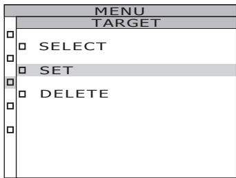
2. Press either or key to select [TARGET] and then press ENTER key.
The MENU - TARGET screen appears.
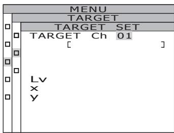
3. Press either or key to select [SET] and then press ENTER key.
The MENU - TARGET - SET screen appears.
4. Change target color channels by pressing or key, and select the channel used to register a target color.
key for larger number. If kept pressed, the number continuously increases.
key for smaller number. If kept pressed, the number continuously decreases.
Once a target color is registered, the status before registration cannot be restored. If the target colors are changed by overwriting, confirm the channel number before making the change.
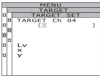
5. Press ENTER key.
The screen used for input of the target color ID appears on the LCD.
6. Enter the target color ID.
When the O key is pressed, the characters change among 0 to 9, a to z, A to Z, and space. When the O key is pressed, the characters change among space, Z to A, z to a, and 9 to 0. When O key is pressed, the cursor moves to the right by one position.
When key is pressed, the cursor moves to the left by one position.
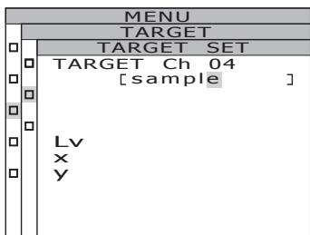
7. Press ENTER key.
The screen used to select a target color appears on the LCD.
By pressing ESC key, the input of the target color is canceled and the MENU - TARGET screen appears again on the LCD.
8. Press either or key to select data to be a target color.
When the O key is pressed, values are changed among, M00 to M99, EDT, and MES. If kept pressed, the value continuously changes. When the O key is pressed, values are changed among MES, EDT, and M00 to M99. If kept pressed, the value continuously changes.
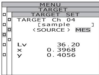
9-a-1. Selection of a measurement value as a target color: Select [MES] and press ENTER key.
When the target color is registered, the MENU - TARGET screen appears again on the LCD. By pressing ESC key, the registration of the target color is canceled and the MENU - TARGET screen appears again on the LCD.
9-b-1. Selection of a memory data as a target color: Select from [M00~M99] and press ENTER key.
When the target color is registered, the MENU - TARGET screen appears again on the LCD. By pressing ESC key, the registration of the target color is canceled and the MENU - TARGET screen appears again on the LCD.
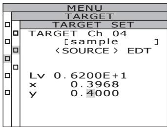
9-c-1. Manual input of a target color: Select [EDT] and press ENTER key.
The screen used to input a target color with a numerical value appears on the LCD.
![KONICA CS-2000 - 9-c-1. Manual input of a target color: Select [EDT] and press ENTER key. - 1](/content/2025/01/172147/images/5962fb58f21f8b68b3fc8ebf9c15d6aaaf23ed39f3d2ab98afa2c0f867d4c29e.jpg)
![KONICA CS-2000 - 9-c-1. Manual input of a target color: Select [EDT] and press ENTER key. - 2](/content/2025/01/172147/images/232ca127ab3cdbdae6b2bbd239615578d374250c9e6336fdf98c76ab26159c19.jpg)
![KONICA CS-2000 - 9-c-1. Manual input of a target color: Select [EDT] and press ENTER key. - 3](/content/2025/01/172147/images/e2c566e83bb68900b03227b73ca0d72c7bb7808199ccc0d2c22709f5745ce0ad.jpg)
9-c-2. Enter the target color.
key for larger number.
If kept pressed, the value continuously increases.
key for smaller number.
If kept pressed, the value continuously becomes small.
When key is pressed, the cursor moves to the right by one position.
When key is pressed, the cursor moves to the left by one position.
9-c-3. Press ENTER key.
When the target color is registered, the MENU - TARGET screen appears again on the LCD.
When observer angle is 10^ , Y is displayed instead of Lv and registered as Y10 .
If the entered value does not establish a combination with the value in the color space mode, the numerical value is cleared. Enter another value again.
By pressing ESC key, the registration of the target color is canceled and the MENU -TARGET screen appears again on the LCD.
10. Press ESC key.
The MENU screen appears again on the LCD.
11. Press ESC key.
The MEAS screen appears again on the LCD.
Selecting Target Color
Select a target color for color-difference measurement from the channels Ch01 to Ch20. The new set color is also applied to the measurement value displayed on the current MEAS screen.
Operation Procedure
1. Press MENU key when the MEAS screen is displayed.
The MENU screen appears.
When the backlight of the LCD has been turned off via BACKLIGHT key on the MEAS screen, the backlight is turned on.
2. Press either or key to select [TARGET] and then press ENTER key.
The MENU - TARGET screen appears.
![KONICA CS-2000 - Press either or key to select [TARGET] and then press ENTER key. - 1](/content/2025/01/172147/images/a10b081562651a0f97d3ff8254e2bb4a4113c3d0e2d966bf0f52a64c92083bb6.jpg)
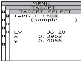
3. Press either or key to select [SELECT] and then press ENTER key.
The MENU - TARGET - SELECT screen appears.
![KONICA CS-2000 - Press either or key to select [SELECT] and then press ENTER key. - 1](/content/2025/01/172147/images/61ca54314db60118a40766af7572352f7cfb664c4eb126744eec5e966a3ec2ab.jpg)
![KONICA CS-2000 - Press either or key to select [SELECT] and then press ENTER key. - 2](/content/2025/01/172147/images/231b1c999b1aed7a28ac6b7ea6228fb0ba71c1d8f8dea76ecb4c9bad6ebf1668.jpg)
4. Press either or key to switch the target color channel.
key for larger number.
If kept pressed, the number continuously increases.
key for smaller number.
If kept pressed, the number continuously decreases.
5. Press ENTER key.
When the target color is set, the MENU -TARGET screen appears again on the LCD. By pressing ESC key, the selection of the target color is canceled and the MENU -TARGET screen appears again on the LCD.
6. Press ESC key.
The MENU screen appears again on the LCD.
7. Press ESC key.
The MEAS screen appears again on the LCD.
The registered target color can be deleted in the following procedure.
Operation Procedure
1. Press MENU key when the MEAS screen is displayed.
The MENU screen appears.
When the backlight of the LCD has been turned off via BACKLIGHT key on the MEAS screen, the backlight is turned on.
| <MEAS SNGL> | UC00 | T01 | |
| Lv | 35.93 | cd/m2 | |
| x | 0.3968 | ||
| y | 0.4060 | ||
| Obs | SPD | SYNC | LEN |
| 2° | Nrm | Non | Std Non |
| MENU |
| MEAS |
| MEMORY |
| TARGET |
| OPTION |
| SETUP |
2. Press either or key to select [TARGET] and then press ENTER key.
The MENU - TARGET screen appears.
| MENU | |
| TARGET | |
| SELECT | |
| SET | |
| DELETE |
3. Press either or key to select [DELETE] and then press ENTER key.
The MENU - TARGET - DELETE (Target color deletion) screen appears.
| MENU | |
| TARGET | |
| TARGET DELETE | |
| TARGET Ch01 | |
| [ | ] |
| Lv | |
| x | |
| y | |
4. Press either or key and select the number to delete the desirable memory data or [ALL]. Press ENTER key.
key for larger number. If kept pressed, the value continuously changes. [ALL] is displayed after Ch 20.
key for smaller number. If kept pressed, the value continuously changes. [ALL] is displayed after Ch 00.
The confirmation screen to delete the target color appears.
![KONICA CS-2000 - Press either or key and select the number to delete the desirable memory data or [ALL]. Press ENTER key. - 1](/content/2025/01/172147/images/5d777a72f3b9601259fdffe7daf39d4dba6a9d18730557eba2e2339f2876b394.jpg)
5.-a-1. Deletion of target colors one by one:
Press key to select [OK] and then press ENTER key.
The display of the registered target color disappears.
By selecting [CANCEL] and pressing ENTER key, or pressing ESC key, the deletion of the target color is canceled ar the MENU - TARGET screen appears again on the LCD.
![KONICA CS-2000 - Press key to select [OK] and then press ENTER key. - 1](/content/2025/01/172147/images/2d3089d53f8d107519f745fbc330a90598a8ed35215d987bd7bb068396ff54fc.jpg)
5.-a-2. To delete another target color continuously, repeat the steps 4 through 5-a-1. as necessary.
5.-a-3. Press ESC key.
The MENU - TARGET screen appears again on the LCD.
5.-b-1. Collective deletion of all target colors:
key to select [OK] and then press ENTER key.
When all target colors are deleted, the MENU - TARGET screen appears again on the LCD.
By selecting [CANCEL] and pressing ENTER key, or pressing ESC key, the deletion of the target color is canceled and the MENU - TARGET screen appears again on the LCD.
By pressing ESC key, the selection of the target color is canceled and the MENU -TARGET screen appears again on the LCD.
![KONICA CS-2000 - key to select [OK] and then press ENTER key. - 1](/content/2025/01/172147/images/ee9d02850440596aff7ea7c6e41ff33df261d1c83d59ce4e178d11f90de7d187.jpg)
6. Press ESC key.
The MEAS screen appears again on the LCD.
7. Press ESC key.
The MEAS screen appears again on the LCD.
Communication
Connecting to PC
This instrument can be used together with PC for mutual communication. Use the USB cable (2m) CS-A32 supplied as standard accessory for this purpose.
The USB cable is allowed to plug/unplug while power is on, but it is recommended to switch power off in this case.
Operation Procedure
- Switch power OFF (O).
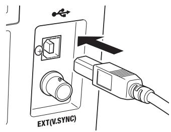
- Connect the USB cable to the USB connector of this instrument.
- Make sure that USB cable is all seated to the USB connector.
Communication interface in this instrument conforms to USB1.1.
Hold the USB cable plug in unplugging. Do not pull the cord.
Plug the USB cable to fit the connector entry point.
To connect this instrument to PC, install the corresponding USB driver software. It is attached to the data management software CS-S10w Professional in the standard accessories. See installation guide of CS-S10w Professional for details on installing the USB driver software to PC.
Remote Mode
Remote mode refers to sending command from PC to this instrument with both connected.
If this instrument is controlled with PC, "REMOTE MODE" appears on the LCD. While this message is displayed, key operation of this instrument is not acceptable except for following cases.
- If the measurement button is pressed, measurement starts to forward the data to PC. (in case that measurement button is in valid mode by transferring command from PC to this instrument. Use data management software below.)
- When ESC key is pressed, the remote mode is canceled.
To control this instrument with PC, use the data management software CS-S10w Professional in the standard accessories. See instruction manual of CS-S10w Professional for details on the specifications and usage.
If you want to use an independent program on PC to control this instrument, download Communication Specifications from KONICA MINOLTA SENSING's website at URL below for your reference
http://konicaminolta.com/instruments/download/software/index.html
(The above URL is subject to change without notice.)
(It the target page will not appear, please search the site by keywords, CS-2000 and download.)
Explanation
Measurement Principle
Light energy passes through the objective lens. The lights from the measurement area pass through the hole in the center of the aperture mirror to the optical fiber, while the remaining light is guided to the finder optics by the aperture mirror. As a result, the part equivalent to the measurement area looks like a black circle when observed through the finder.
The light entering the optic fiber is reflected repeatedly so that it is mixed and becomes virtually uniform. It then passes through the collimator lens to the plane diffraction grating. After being dispersed by the grating, the light is focused by the condenser lens according to wavelength. An array sensor is located at this focus point.
The amount of detected energy for each wavelength is then converted to a digital value by an A/D converter, based on which the spectral radiant luminance and chromaticity are calculated by the processing section of the CS-2000.
Sensor Section
The sensor section has a photo diode array consisting of 512 elements. The array is always kept at constant temperature using a Peltier cooler, irrespective of the ambient temperature. This can reduce dark current and improve S/N ratio, thus enabling
measurement of low luminance.
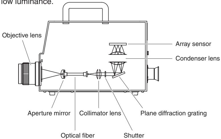
Dark Measurement
Each measurement consists of "light measurement" and "dark measurement".
"Light measurement" is performed with light from the object irradiating the sensor, while "dark measurement" is performed with no light from the object irradiating the sensor, so that detector dark current is measured.
When measurement starts, first "light measurement" is performed. When "light measurement" is complete, the shutter will close automatically, then "dark measurement" starts immediately. "Dark measurement" is performed with the same integration time used for "light measurement".
The final measured data is obtained by subtracting the measured data obtained in "dark measurement" from the one obtained in "light measurement". This method eliminates influences of dark current of the array sensor, resulting in improved measurement accuracy.
Following factors can be acquired as measurement value with L_vT uv as color space of this instrument.
L_v : Luminance
T :Correlated color temperature
Δuv :Color difference from blackbody locus
While L_vs stands for luminance, T and u v for color in L_vT u v
Color temperature refers to the temperature of black body (perfect radiator) which has equal chromaticity coordinates to certain light. However, color temperature only represents colors on blackbody locus.
Correlated color temperature, slightly wider interpretation of color temperature, is very useful to eliminate such problem. Here, correlated color temperature covers those which are slightly outside the range of that of blackbody locus.
If a certain color positions on isotemperature line, the intersection point of isotemperature line and blackbody locus is indicated as correlated color temperature for the color.
Isotemperature line means line on chromaticity coordinates which is a set of colors visually close to color temperature on blackbody locus.
However, since all colors on a color-matching temperature line are represented with equal correlated color temperature, it is not possible to describe color only with correlated color temperature. To solve that, u v , deviation of correlated color temperature T from blackbody locus, is to apply for that purpose.
If u v exists above blackbody locus, it is represented with ^ 一 + ^ 一 , and below, with -
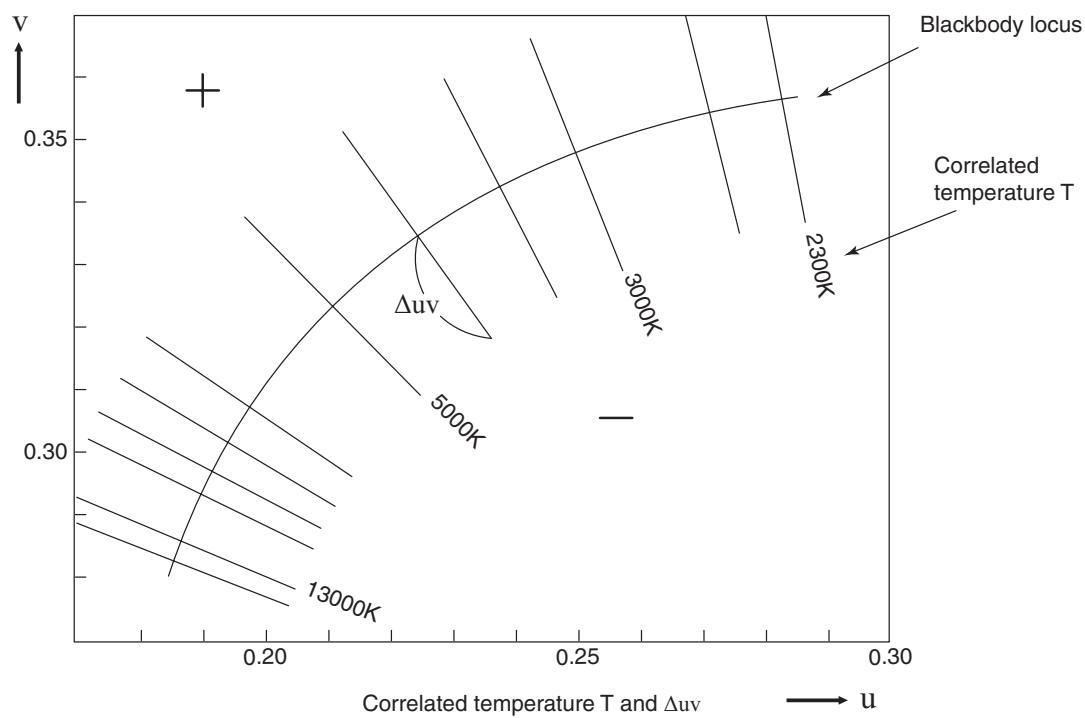
Dominant wavelength/Excitation purity
In the x, y chromaticity diagram shown below, the curve VScSR is the spectrum locus, and point N is the white point (the chromaticity point of the perfect reflecting diffuser).
Colors located in the region enclosed by the spectrum locus and the straight lines VN and NR are referred to as spectral colors; colors located in the triangle NVR with the white point N at the apex and the pure purple line VR as the base are referred to as nonspectral colors.
When the chromaticity point obtained by the measurement is C, the wavelength corresponding to the intersection point S of the extension of NC with the spectrum locus (curve VScSR) is referred to as the dominant wavelength and indicated by the symbol _d . The ratio of the lengths of the straight lines NC and NS is referred to as the excitation purity of color excitation C and indicated by the symbol p_e .
When the chromaticity point obtained by measurement is C' , the extension of NC' toward C' does not intersect with the spectrum locus but only the pure-purple lines. In this case the wavelength corresponding to the intersection point S_c of the extension of NC' toward N with the spectrum locus is referred to as the complementary wavelength and indicated by the symbol c . When the intersection point of the extension of the line NC' with the line VR (pure-purple locus) is designated by S' , the ratio of the lengths of NC' to NS' is referred to as excitation purity and indicated by the symbol p_v' .
The following equations are formulated, if each point is designated as the following coordinates: (xn,y_n) : chromaticity coordinate of point N; (xc,yc) : chromaticity coordinate of point C; (x,y) : chromaticity coordinate of point S, (xc^,yc) : chromaticity coordinate of point C', and (xp,y_p) : chromaticity coordinate of point:
Excitation purity (spectral colors)
$$ p _ {e} = \frac {x _ {c} - x _ {n}}{x - x _ {n}} = \frac {y _ {c} - y _ {n}}{y - y _ {n}} $$
Excitation purity (non-spectral colors)
$$ p _ {e} ^ {\prime} = \frac {x _ {c} ^ {\prime} - x _ {n}}{x _ {p} - x _ {n}} = \frac {y _ {c} ^ {\prime} - y _ {n}}{y _ {p} - y _ {n}} $$
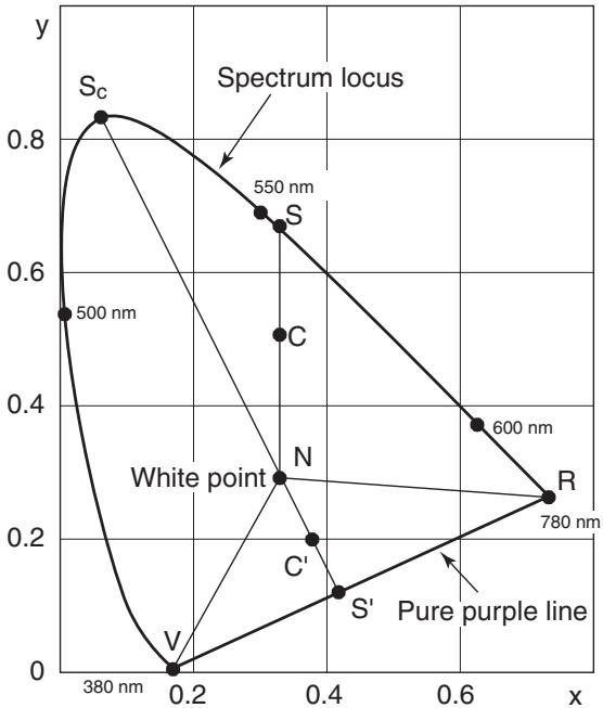
Dominant wavelength on chromaticity diagram
Measurement of Object Color
Use of the data management software CS-S10w Professional in the standard accessories enables simple measurement of the color of the object. Measured data is evaluated based on luminance which has been stored as light source data in CS-S10w. See instruction manual of CS-S10w for details.
- Set while calibration plate (optional accessory) and object on the same position with the same angle from this instrument. Uniform illumination and measurement conditions of white calibration plate and those of object. If not, measurement data may vary, causing incorrect data.
- Keep illumination light source as stable as possible with fixed voltage power source during measurement.
Measurement Procedure
Necessary Setting for Object Color Measurement
1. Set one or more tungsten lumps or equivalent as illumination source toward white calibration plate as in the right illustration.
- Set this instrument vertical to white calibration plate.
- Keep the angle between illumination light source and white calibration plate at 45^ .
2. Start up this instrument, PC, and software CS-S10w.
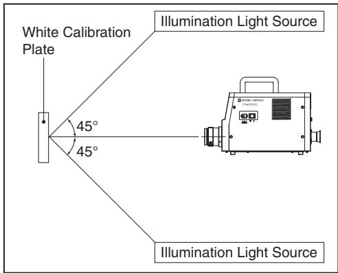
White Calibration
- Set the document type to "object color" with CS-S10w.
- Conduct white calibration with CS-S10w.
Measurement of Object
- Set object on the same position and at the same angle as white calibration plate.
- Conduct measurement with CS-S10w.
See instruction manual of data management software CS-S10w for details.
(Unit: mm)
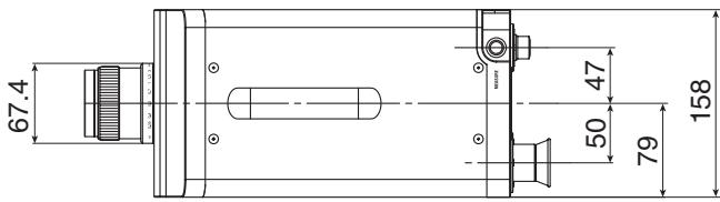
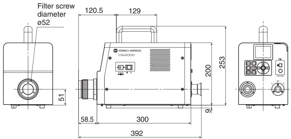
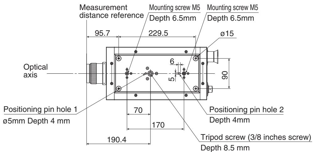
Error Message
Error message appears on the LCD when this instrument does not operate normally. Below table shows type of error message, its description and corrective action respectively.
| Error Message | Cause (Description) | Corrective action | |
| 1 | MEMORY ERROR | Data stored in ROM is damaged. | Turn on the power switch again. If the symptoms are not remedied, please contact the nearest KONICA MINOLTA SENSING authorized service facility. |
| 2 | OVER | Luminance of measuring object is higher than the available range. Flicker of measuring object is high. | Use the ND filter and re-measure. Decrease the measuring area and re-measure. If the symptoms are not remedied, please contact the nearest KONICA MINOLTA SENSING authorized service facility. Set the flicker cycle in INT SYNC mode, or input the flicker signal in EXT SYNC mode. |
| 3 | SYNC ERROR | Input signal in EXT SYNC mode is not at CMOS level. Input signal in EXT SYNC mode exceeds 200 Hz. Input signal in EXT SYNC mode is less than 20 Hz. | Input a signal with 3.5 to 5.0 V at high level; 0.0 to 1.5 V at low level. Set the frequency value divided by an integer in INT SYNC mode and re-measure. Set the integral multiple value of the input signal cycle in INT SYNC mode and re-measure using the MULTI INTEG mode. Set the integral multiple value of the input signal cycle in INT SYNC mode and re-measure using the MANUAL mode. |
| 4 | VIEWING-ANGLE SELECTOR ERROR | Measurement was performed when the measuring angle selector was in the wrong position, or its position was changed during measurement. | Switch the measuring angle selector and re-measure. Or, do not operate the measuring angle selector during measurement. If the symptoms are not remedied, please contact the nearest KONICA MINOLTA SENSING authorized service facility. |
| 5 | TEMPERATURE ERROR | The ambient temperature for the measurement device is too high, and an internal temperature of the sensor becomes abnormal. The cooling fan stops, or the cooling device has an error. | Decrease the ambient temperature to enable cooling to within the specified temperature. Turn off the power switch once, turn it on again after a while. If the symptoms are not remedied, the fan must be repaired. Please contact the nearest KONICA MINOLTA SENSING authorized service facility. |
Should any errors be found in this instrument, try the corrective actions shown in the following table. If this does not help, it's possible the instrument is broken. Please contact the nearest KONICA MINOLTA SENSING authorized service facility with the error number and version of your instrument. To confirm the instrument version, see p.23.
| Error No. | Symptom | Item to Check | Corrective Action | Reference Page |
| 1 | No display on the LCD after power is turned on. | Has the AC adapter been properly plugged into the AC outlet? | Connect the AC adapter. | 21 |
| Has the AC adapter been connected to this instrument? | Connect the AC adapter. | 21 | ||
| Has a wrong AC adapter been connected? | Be sure to use the AC adapter and power cord supplied as a standard or optional accessory (AC-A312). | 21 | ||
| Is AC power source within rated scale? | Use within ±10% of the nominal voltage. | 21 | ||
| 2 | Nothing is visible through the finder. | Is the lens cap still attached to the objective lens? | Remove the lens cap. | 8 |
| Is the ND filter attached to the objective lens? | Use the ND filter when the luminance of that being measured is too high. | 9, 44 | ||
| Is the ND eyepiece filter attached to the finder? | Use the ND eyepiece filter when luminance of that being measured is too high. | 9, 44 | ||
| 3 | Nothing is displayed on the LCD. | Is the backlight set to OFF? | Press BACKLIGHT key to turn ON the backlight. | 14, 48 |
| Has the backlight been set to OFF during measurement? | In the menu operation, set the backlight to ON during measurement | 48 | ||
| 4 | Does not accept key operation. | Has the remote mode been set? | Press ESC key to cancel the remote mode. | 73 |
| Have you pressed a disabled key? | Press the correct key. | — | ||
| 5 | Measurement unavailable even if the measurement button is pressed. | Has a screen other than MENU been displayed? | Conduct measurement when the MEAS screen is displayed. | 53 |
| 6 | The entered value for target color is different from the one that will be displayed after setting. | A 1-digit difference may be found due to calculation error. | 61 | |
| 7 | Measurement values do not appear. | Is there data? | Conduct measurement. | 52 |
| Has the color space mode become color temperature? | Color temperature is not displayed if it is far from the blackbody locus. Change the display using the other color space mode and check. | 38 | ||
| Did you interrupt measurement? | Conduct measurement again. | 52 | ||
| 8 | Measurement values are inconsistent. | Is the measuring object stable? | Conduct measurement with the measuring object stable. | — |
| Is the measuring object of low luminance? | Repeatability of x, y worsens if the measuring object of low luminance is measured. | 52, 30 | ||
| It especially worsens when the measurement angle is 0.2° or 0.1°. | ||||
| It also worsens when the measurement time is short. Make the measurement time longer. | ||||
| Is the measurement sync frequency appropriate when measuring the display? | Set the appropriate measurement sync frequency. | 26, 30 | ||
| Use MULTI INTEG mode. | ||||
| Measure in EXT SYNC mode. | ||||
| Have the ambient temperature and/or humidity changed rapidly? | Conduct measurement under an environment free from rapid changes in ambient temperature and humidity. | 3 | ||
| Did you start measurement immediately after startup? | Allow the instrument to warm up for 20 minutes or more when the power switch is turned on. | 23 | ||
| 9 | Measurement values appear incorrectly. | Is the objective lens clean? | Wipe off the lens with a dry, soft cloth or lens cleaning paper. | 52 |
| User calibration may not be performed correctly. | Check the values without user calibration (i.e. set the calibration channel to 00 (NON) and check). | 46 | ||
| Is the calibration channel correct? | Select the calibration channel according to the light source of luminance and chroma close to the object. | 46 | ||
| Has the closeup lens been attached? | Select the lens type setting according to the attached closeup lens. | 42, 52 | ||
| Has the ND filter been attached? | Select the ND filter setting according to the attached ND filter. | 44 | ||
| Has the object been focused? | Adjust the focus after adjusting the diopter. | 13, 15 52 | ||
| 10 | The measurement stops halfway and does not finish in the set measurement time. | Is the measuring object of high luminance? | When measuring an object of high luminance, the sensor may be saturated by exceeding the upper limit of the current measurement setting. | 44 |
| Use the ND filter. | ||||
| 11 | Actual measurement time is different from the displayed measurement time. | The displayed measurement time is the remaining time. The actual measurement time may be different from the displayed time depending on the mode setting of measurement time. | 30 | |
| 12 | Measurement value on the LCD disappears. | Has the power source been supplied securely? | Connect to a stable power source and insert the AC adapter plug securely. | 21 |
| Did you interrupt the measurement? | When starting continuous measurement, press the measurement button securely. Do not press ESC key. | 54 | ||
| 13 | During USB communication: Cannot download data output from this instrument on the PC. Cannot enter commands or data from the PC to this instrument. | Has the USB cable been connected securely? | Connect this instrument and the PC securely. | 72 |
| Has the USB cable been disconnected? | Replace the USB cable. | — | ||
| Has remote mode been canceled? | Send the connection command from the PC to this instrument and switch to remote mode. Use the data management software CS-S10w in the standard accessories. | 73 | ||
| Has the program been prepared correctly? | Refer to communication specifications and check the program. Use the data management software CS-S10w in the standard accessories. | — | ||
| 14 | Same error message appears repeatedly. | Check the appropriate corrective action for the error message. | If the symptoms are not remedied, please contact the nearest KONICA MINOLTA SENSING authorized service facility. | — |
Setting Initialization
Preset measurement conditions can be initialized to the factory default settings according to the following procedure.
Factory default settings are shown below.
- Synchronizing method
:NO SYNC
- Measurement time
:MULTI INTEG,1s
*Observer
:2°OBS
- Display format
:*.*[F]
- Color space mode
:Lvxy
- Absolute value (ABS)/Difference (DIFF) display
: Absolute value (ABS)
- Lens type
:STANDARD
- ND filter type
:NONE
- Backlight during measurement : ON
Operation Procedure
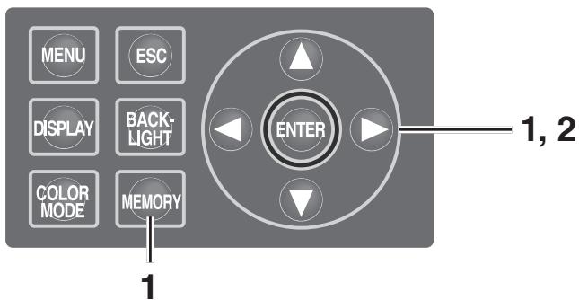
1. When the power switch is OFF (O), turn it to ON (I) while pressing MEMORY key, key and key simultaneously.
The INITIALIZE SETTINGS (confirmation of setting initialization) screen appears approx. 5 seconds after the initial screen on the LCD. Continue pressing key, key and key until the INITIALIZE SETTINGS screen appears.
2. Press key to select [OK] and then press ENTER key.
The preset measurement conditions are initialized and the MEAS screen appears on the LCD.
![KONICA CS-2000 - Press key to select [OK] and then press ENTER key. - 1](/content/2025/01/172147/images/a25dddba4cf2cb89825e52a8da3a7cbd7cffa3da8488ce7a2b3ad37fc14613bf.jpg)
![KONICA CS-2000 - Press key to select [OK] and then press ENTER key. - 2](/content/2025/01/172147/images/5dbe8423f7786794d1de329ebb4ff42af40707aa6bbf639f430a0872a64ada19.jpg)
Switching Luminance Unit
You can select [cd / m^2 ] or [fL] as the luminance unit.
Operation Procedure
1. When the power switch is OFF (O), turn it to ON (I) while pressing MENU key and key simultaneously.
The Luminance Unit (switching luminance unit) screen appears approx. 5 seconds after the initial screen on the LCD.
Continue pressing MENU key and key until the Luminance Unit screen appears.
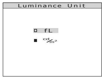
2. Press either or key to select the luminance unit and then press ENTER key.
The setting is entered and the MEAS screen appears on the LCD.
| Model | CS-2000 | ||
| Wavelength range | 380 to 780 nm | ||
| Wavelength resolution | 0.9 nm/pixel | ||
| Display wavelength bandwidth | 1.0 nm | ||
| Wavelength precision | ±0.3 nm (median wavelength: 435.8 nm, 546.1 nm, 643.8 nm Hg-Cd lamp) | ||
| Spectral bandwidth | 5 nm or less (half bandwidth) | ||
| Measuring angle (selectable) | 1° | 0.2° | 0.1° |
| Measurement luminance range (Standard light source A) | 0.003 to 5,000 cd/m2 | 0.075 to 125,000 cd/m2 | 0.3 to 500,000 cd/m2 |
| Minimum measuring area | ø5 mm(ø1 mm when using closeup lens) | ø1 mmø0.2 mm when using closeup lens) | ø0.5 mmø0.1 mm when using closeup lens) |
| Minimum measuring distance | 350 mm (55 mm when using closeup lens) | ||
| Minimum luminance display | 0.00002 cd/m2 | ||
| Minimum spectral radiance display | 1.0×10⁻⁹W/sr, m2, nm | ||
| Accuracy: Luminance (Standard light source A)*1 | ±2% | ||
| Accuracy: Chromaticity (Standard light source A)*1 | x,y :±0.003 (0.003 to 0.005 cd/m2)x,y :±0.002 (0.005 to 0.05 cd/m2)x :±0.0015 (0.05 cd/m2 or more)y :±0.001 | x,y :±0.003 (0.075 to 0.125 cd/m2)x,y :±0.002 (0.125 to 1.25 cd/m2)x :±0.0015(1.25 cd/m2 or more)y :±0.001 | x,y :±0.003 (0.3 to 0.5 cd/m2)x,y :±0.002 (0.5 to 5 cd/m2)x :±0.0015(5 cd/m2 or more)y :±0.001 |
| Repeatability: Luminance (2 σ) | 0.4% (0.003 to 0.05 cd/m2)0.3% (0.05 to 0.1 cd/m2)0.15% (0.1 to 5,000 cd/m2) | 0.4% (0.075 to 1.25 cd/m2)0.3% (1.25 to 2.5 cd/m2)0.15% (2.5 to 125,000 cd/m2) | 0.4% (0.3 to 5 cd/m2)0.3% (5 to 10 cd/m2)0.15% (10 to 500,000 cd/m2) |
| Repeatability: Chromaticity (2 σ) | 0.002 (0.003 to 0.005 cd/m2)0.001 (0.005 to 0.1 cd/m2)0.0006 (0.1 to 0.2 cd/m2)0.0004 (0.2 to 5,000 cd/m2) | 0.002 (0.075 to 0.125 cd/m2)0.001 (0.125 to 2.5 cd/m2)0.0006 (2.5 to 5 cd/m2)0.0004 (5 to 125,000 cd/m2) | 0.002 (0.3 to 0.5 cd/m2)0.001 (0.5 to 10 cd/m2)0.0006 (10 to 20 cd/m2)0.0004 (20 to 500,000 cd/m2) |
| Polarization error | 1°: 2% or less (400 to 780 nm); 0.1° and 0.2°: 3% or less (400 to 780 nm) | ||
| Integration time | Fast: 0.005 to 16 sec.; Normal: 0.005 to 120 sec. | ||
| Measurement time | 2 sec. min. (Manual mode) to 243 sec. max. (Normal mode) | ||
| Color space mode | Lv x y, Lvu'v', LvT uv, XYZ, dominant wavelength, spectral graph | ||
| Interface | USB 1.1 | ||
| Operating temperature/ humidity range | 5 to 35°C, relative humidity 80% or less with no condensation | ||
| Storage temperature/ humidity range | 0 to 45°C, relative humidity 80% or less with no condensation | ||
| Size | Main unit: 158 (W) x 200 (H) x 300 (D) mm; Lens: ø70 x 95 mm | ||
| Weight | 6.2 kg | ||
*1: Average of 10 measurements in Normal mode at a temperature of 23 ± 2^ C and a relative humidity of 65 % or less.


KONICA MINOLTA