
NODE 2 - Ordinateur de vélo BONTRAGER - Notice d'utilisation et mode d'emploi gratuit
Retrouvez gratuitement la notice de l'appareil NODE 2 BONTRAGER au format PDF.

| Type de produit | Ordinateur de vélo |
| Marque | Bontrager |
| Modèle | NODE 2 |
| Alimentation | Pile CR2032 3V (ordinateur et capteurs) |
| Autonomie | Environ 10 mois pour 1 heure d'utilisation par jour |
| Fonctions principales | Vitesse (actuelle, moyenne, max), cadence, fréquence cardiaque, puissance, altitude, temps de parcours, calories, intervalles, double vue, rétroéclairage |
| Affichage | Écran LCD avec rétroéclairage (5 secondes) |
| Capteurs compatibles | Vitesse, cadence, fréquence cardiaque, puissance (ANT+) |
| Connectivité | ANT+ sans fil |
| Portée de transmission | Environ 1,5 mètre (5 pieds) |
| Résistance à l'eau | Résistant aux éclaboussures (non immergeable) |
| Compatibilité vélos | Jusqu'à 2 vélos avec tailles de roues différentes |
| Réinitialisation | Bouton Reset à l'arrière de l'ordinateur |
| Entretien | Remplacement des piles tous les 10 mois ; nettoyer avec un chiffon doux |
| Sécurité | Ne pas regarder fixement l'écran pendant la conduite |
FOIRE AUX QUESTIONS - NODE 2 BONTRAGER
Questions des utilisateurs sur NODE 2 BONTRAGER
0 question sur cet appareil. Repondez a celles que vous connaissez ou posez la votre.
Poser une nouvelle question sur cet appareil
Téléchargez la notice de votre Ordinateur de vélo au format PDF gratuitement ! Retrouvez votre notice NODE 2 - BONTRAGER et reprennez votre appareil électronique en main. Sur cette page sont publiés tous les documents nécessaires à l'utilisation de votre appareil NODE 2 de la marque BONTRAGER.
MODE D'EMPLOI NODE 2 BONTRAGER

BONTRAGER
NODE™ 1 & NODE™ 2
Owner's Manual.
WELCOME.
Thank you for buying a Bontrager NODE™ computer. We hope this computer gives you miles (or kilometers) of pleasure.
Please read this manual carefully. If you do not understand the information, or you have a question that this manual does not cover, consult your Bontrager dealer or contact us.
Safety When Riding
When riding your bicycle, do not stare at the computer for a long time (Figure 1). If you do not watch the road, you could hit an obstacle, which may cause you to lose control and fall.
Terms Used
| Hold | Press a button continuously for about three seconds. |
| Press | Push a button once, briefly. |
| Reset | Set all values in the memory to 0 (zero) and erase all settings. |
| Trip Restart | Set Trip values (only) in the memory to 0 (zero). |
| Scroll | Press several times to change through a list of values or screen elements. |
| Toggle | Change back and forth between two values or screen elements. |
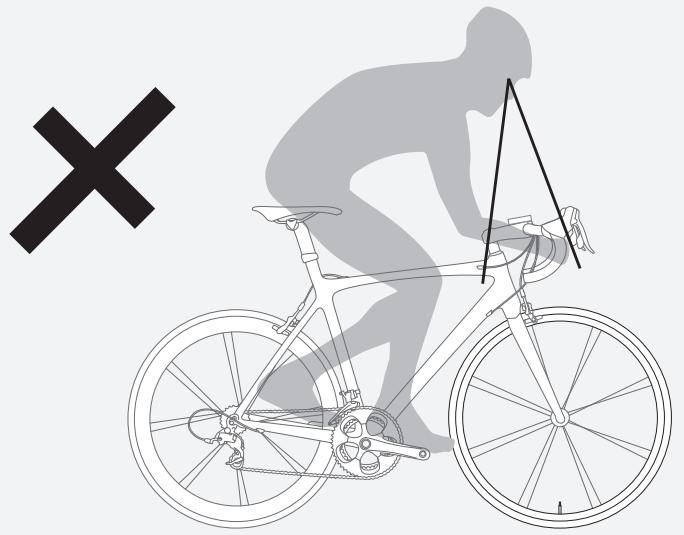
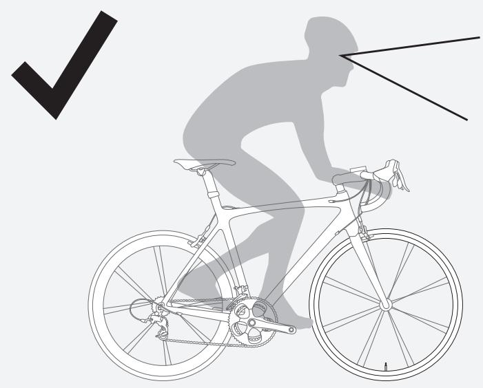
Figure 1. Do Not Stare at Computer for Long Periods of Time.
Screen Elements and Abbreviations
There are two models of NODE computer:
- NODE 1
- NODE 2
Either model can be used on two bicycles with different wheel sizes, yet still calculate all the data correctly. You must set the wheel sizes and choose the bike setting that is appropriate for that bike before you start riding.
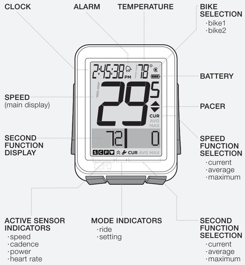
Figure 2. Screen Elements.
Trip Data
can be restarted to 0 without affecting the total)
- Cadence AVG and MAX
- Distance (TRP)
- Heart Rate AVG, MIN, and MAX; plus Zones 1 through 5
Power AVG, MIN, and MAX - Speed AVG and MAX
- Altitude (ALT), +, -, and Grade (%) AVG and MAX
Abbreviations and Screen Terms
| Abbreviation | Meaning |
| ALT | Altitude |
| AVG | Average |
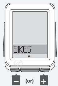
| BIKES | Bicycles, including bike1 and bike2 |
| CAL | Calorie |
| CLOCK | Clock |
| CUR | Current, or now |
| DV | Dual View, showing two secondary functions simultaneously |
| F | Female |
| FT | Feet |
| HR | Heart Rate |
| INT | Interval |
| M | Male |
| MAX | Maximum |
| MIN | Minimum |
| MT | Meters |
| Abbreviation | Meaning |
| NUTRI | Nutrition |
| ODO | Odometer |
| OFF | Off |
| ON | On |
| PWR | Power |
| REPS | Repetitions |
| REST | Rest |
| SENS | Sensors |
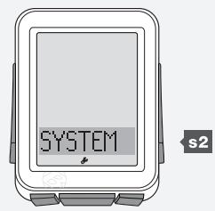
| SYSTEM | System |
| TIME | Time |
| TRP | Trip |
| TTL | Total |
| UNITS | Units |
| WGT | Weight |
Modes
The NODE computer has two modes:
- Ride
- Setting
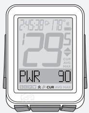
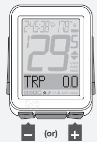
Ride
This is the mode you will use when riding your bike. Ride mode (Figure 3) displays the functions, the information gathered by the computer. This information can be the current data (your current speed, the current temperature, or data from other functions), or for some functions the NODE can display your average, total, or minimum/maximum data. You can learn more about each of these functions in the section that covers functions.
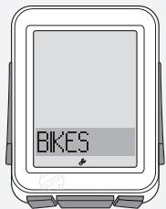
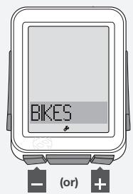
Setting
This is the mode you will use to prepare your computer for your first ride, or to set more advanced features. Setting mode (Figure 4) allows you to program the computer, allowing you to choose the units you prefer (e.g. miles or kilometers), input the correct time or altitude, or set alarms to alert you when you exceed your chosen minimum or maximum heart rate. If the computer is left in Setting mode, it automatically returns to the Ride mode.
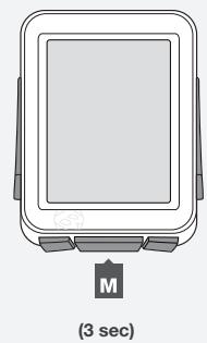
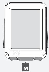
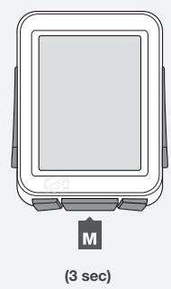
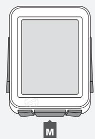
Changing Modes
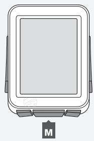
To toggle the Ride and Setting modes, hold M for three seconds (Figure 5).
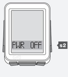
Sleep (Standby)
If the sensors do not send a signal to the NODE for 20 minutes, the computer goes into Standby to conserve battery power. After an additional 10 minutes, the NODE switches to Off.
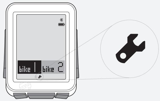
Figure 3. Ride Mode.
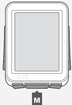
Figure 4. Setting Mode.
(3 sec)
Figure 5. Changing Modes.
Sensors
The NODE can compute information from four sensors:
- Cadence
- Speed
Heart Rate
Power
Not all NODE computers are packaged with all the sensors. If your bicycle is appropriately equipped, you can purchase a combination speed/cadence sensor. You can also customize your computer by purchasing additional Bontrager NODE sensors or a power sensing system of your choice from your Bontrager dealer.
Functions of Sensors
Sensors sense impulses, either from the passing of magnets that are attached to a spoke or a crankarm, electrical impulses generated by the pumping of your heart, or the impulses from a power meter. When the sensor senses input, it sends a radio signal to the NODE computer. This signal has a range of about 5 feet (1.5 meters).
Sensors Require Power
Sensors require electrical power. Each sensor gets its own power from an individual battery. If the battery loses power, the sensor will no longer send signals to the computer.
Before Your First Ride
Pairing (Pair) Procedure
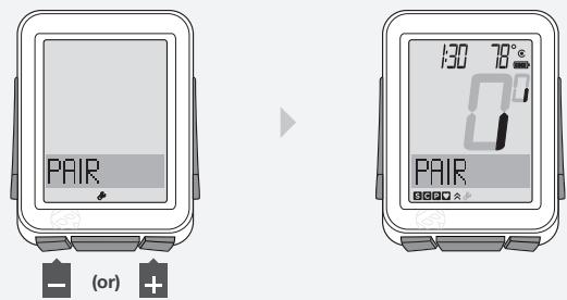
Before the NODE can display any data, it must identify each radio signal sent by the sensors (Figure 6). This process, which takes about one minute, is called "Pairing" (Pair). After the NODE creates a Pair, it remembers the signals, so normally this only occurs once (during the initial set up).
Sensors only send signals when they are activated:
- The wheel must turn to activate the speed sensor
- The crankarm must rotate to activate the cadence sensor or the power sensor
- You must wear the chest strap to activate the heart rate sensor
During the Pairing procedure, the 0 of the speed display flashes. This procedure can take up to 60 seconds. When it is complete, the icons for successfully connected sensors display at the bottom of the screen. If an icon for a sensor disappears, a pair was not created for that sensor.
Force Pair
The NODE only needs to perform the pair procedure once. If the Pair fails, or later you add another sensor, you can also force the Pairing procedure: In Ride mode, hold s1 and s2 for three seconds while you make the sensors send signals.
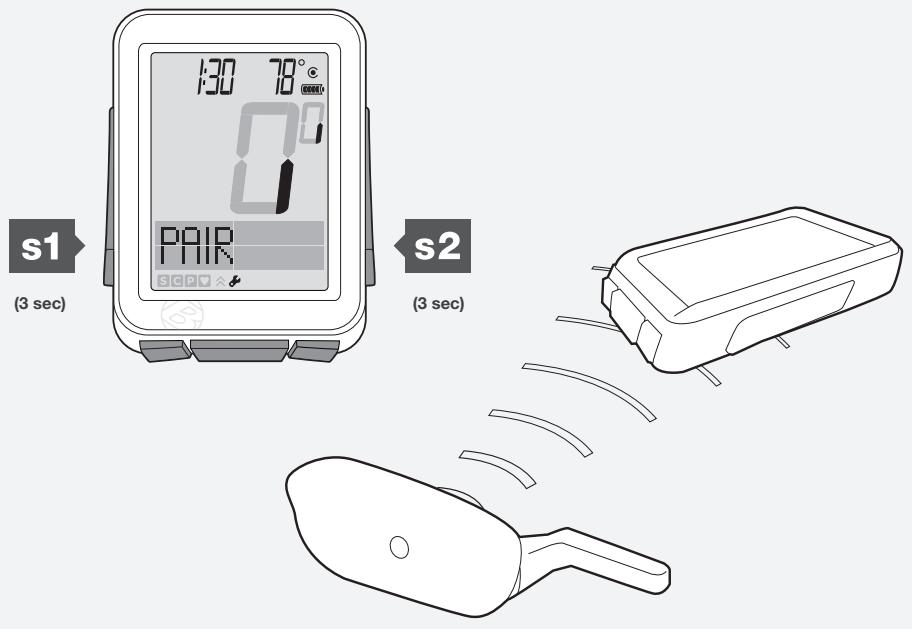
Figure 6. Locking onto Radio Signals from Sensors.
Connecting (Connect) Procedure
Each time you switch on the NODE, it automatically tries to Connect (lock on) to the signals it remembers from the Pairing procedure. Just like during Pairing, for the NODE to Connect to signals you must activate the sensors (make them send a signal).
During the Connecting procedure, the 0 of the speed display flashes. After the Speed sensor connects, the 0 stops flashing but the icons of the other paired sensors continue to flash until the Connecting procedure is complete. This can take up to 60 seconds. When it is complete, the icons for successfully connected sensors display at the bottom of the screen (Figure 7).
Force Connect
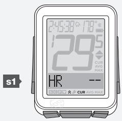
If the Connecting procedure fails, the -- appears on the screen in each function where the sensor is switched to ON but the Connecting procedure failed. In addition, the icon for that sensor will disappear. These indications happen when the NODE does not receive a signal during the Connecting procedure.
You can force the Connecting procedure:
In Ride mode, hold for three seconds while you make the sensors send signals.
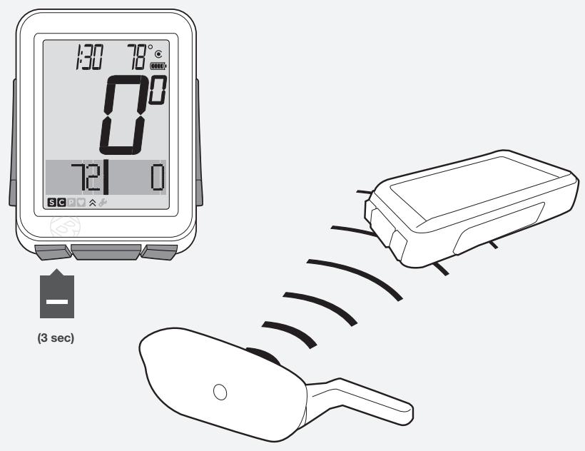
Figure 7. Icons Show Sensors are Connected.
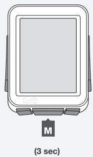
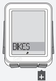
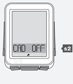
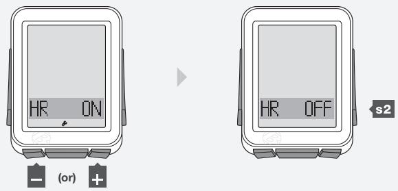
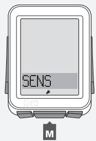
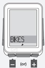
Switching Sensors to OFF or ON
- Hold M for three seconds to go to Setting mode.
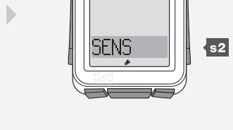
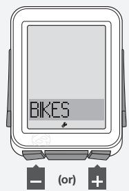
- When BIKES appears, scroll + to SENS.
- Press s2.
1.
2.
3.
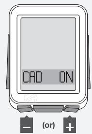
- To change Cadence to ON or OFF, press + or -
To select, press s2.
4.
- To change Power to ON or OFF, press + or -. To select, press s2.
5.
- To change Heart Rate to ON or OFF, press + or -
Press s2.
6.
7.
Automatic Setup
When you switch the NODE to On the first time (or replace the batteries or perform the Reset procedure), the computer will automatically go through the Pairing and Connecting procedures and set the units for one bike.
NOTE Before starting this procedure, place the NODE within 5 feet (1.5 m) of all sensors, and be ready to activate the sensors as explained in Pairing.
- To switch on the computer, hold M for three seconds.
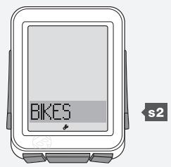
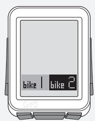
The NODE automatically goes to the Setting mode and bike1 and bike2 display with one highlighted. If it does not, push the Reset (erase settings) button on the back of the computer.
- To change bike1 or bike2, press + or -
To select, press M.
You can go back from any selection: Press s1
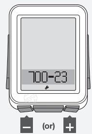
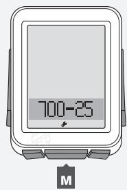
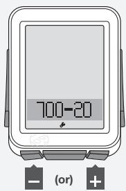
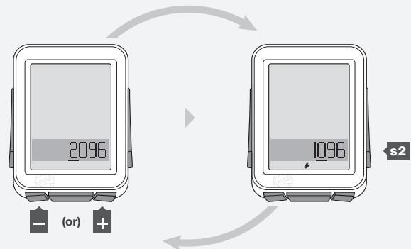
- To change the wheel size, press + or -
To select, press M.
NOTE You can also set a Custom wheel size.
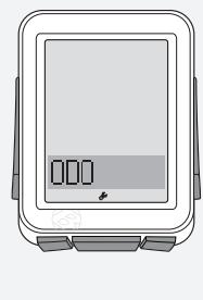
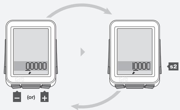
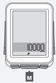
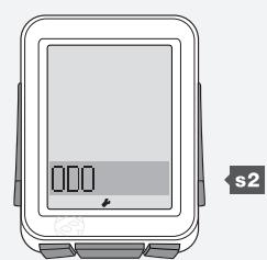
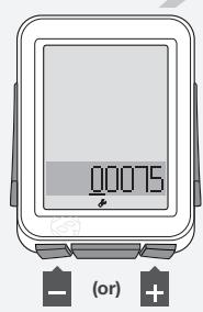
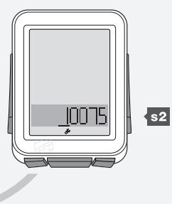
ODO displays, then Ride Total displays (this may be zero) with the first digit underlined.
- To change the underlined digit, press + or -
To select, press s2.
1.
2.
3.
4.
- Repeat Step 4 to change and select the other digits, then press M.
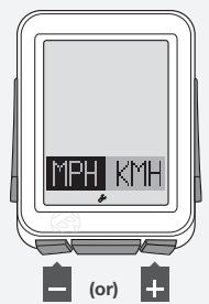
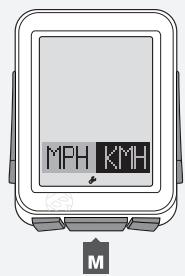
- To change to MPH or KMH, press + or -
To select, press M.
5.
6.
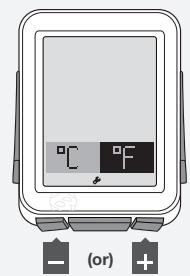
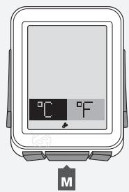
- To change to ^ or ^ , press + or -
To select, press M.
7.
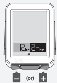
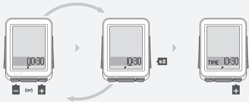
- To change to 12hr or 24hr, press + or -
To select, press s2.
s2
8.
- To change the underlined digit, press + or -
To select, press s2.
Repeat step 9 to change and select the other digits.
If you selected the 12hr clock, you also must select AM or PM.
- When PAIR appears, make the sensor(s) send a signal (spin the wheel, turn the crank, etc.).
The computer indicates it is performing the Pairing procedure.
When the NODE changes to Ride mode with Speed displayed (Figure 8), it is ready for use.
If an icon does not appear after the Pairing procedure, do one of the following:
- Force Pair
- Press the Reset (erase settings) button to start over
See the Troubleshooting section.
9.
10.
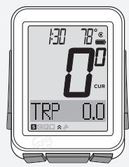
Figure 8. Ride Mode with Speed Displayed.
Advanced Setup
This section explains how to perform setup for a second bike or set a custom wheel size.
To Perform Setup for a Second Bike
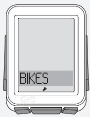
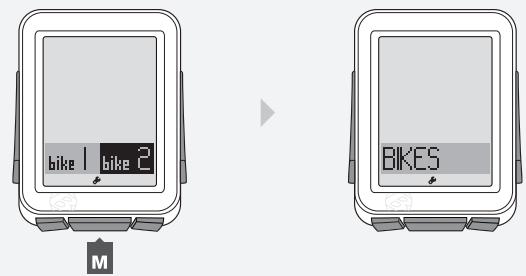
- Hold M for three seconds to go to Setting mode.
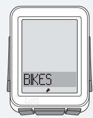
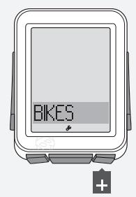
- When BIKES appears, press s2.
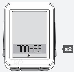
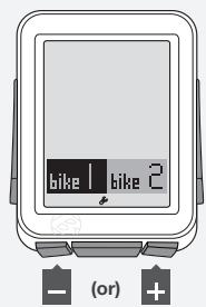
- To change from bike1 or bike2, press + or -
To select, press s2.
-
To change wheel size, press + or -
To select, press s2. -
To save and exit, press M.
To go to Ride mode, hold M for three seconds.
(3 sec)
2.

3.
s2

4.
Setting a Custom Wheel Size
Measure the roll-out (Figure 9).
NOTE Roll-out is the distance your bicycle travels in exactly one revolution of the wheel. If one wheel on your bicycle is bigger, measure the wheel with the magnet.
- With the valve stem of the wheel directly over the floor, sit on the bike.
- Have your helper mark the floor at the valve stem.
- Roll the bike forward one revolution of the wheel, so that the valve stem is again directly over the floor.
- Mark the new location of the valve stem.
- Measure the distance between the marks. If needed, convert to millimeters. The result is your Custom Wheel Size.
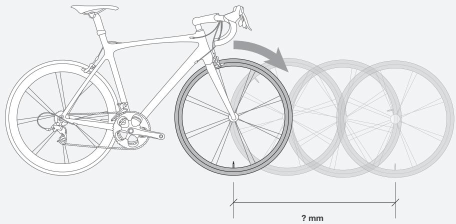
Figure 9. Roll-out.
- Hold M for three seconds to go to Setting mode.
- When BIKES appears, press s2.
- To change bike1 or bike2, press

(3 sec)
2.
3.
To select, press s2
4.Scrollor + or to CUSTOM.
Press s2.
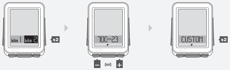
4.
- To change the underlined digit, press + or -
To select, press s2.
Repeat step 5 for the other digits.
5.
- To save and exit, press M.
To go to Ride mode, hold M for three seconds.
6.
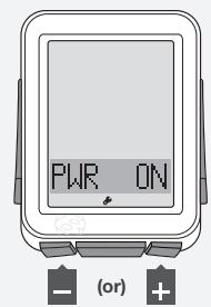
Every Ride After the First
To switch the NODE to "On," simply push any button or send the NODE speed or cadence data: spin the crankarm or roll the wheel. The Connecting procedure will begin immediately.
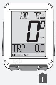
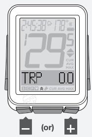
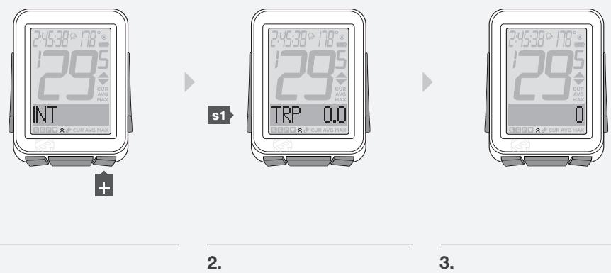
To Restart (Change Trip Data to 0)
- In Ride mode, hold + for three seconds.
NOTE Trip data includes this information:
Cadence AVG and MAX
- Distance (TRP)
- Heart Rate AVG, MIN, and MAX; plus Zones 1 through 5
Power AVG, MIN, and MAX
- Speed AVG and MAX
- Altitude (ALT) +, -, and Grade (%) AVG and MAX
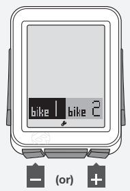
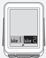
To Select the Bike
The NODE can calculate data for two different bikes, even if they have different sizes of wheels. If you have not performed the Setting procedure for the second bike, see Advanced Setup.
- Hold M for three seconds to go to Setting mode.
- When BIKES appears, press s2.
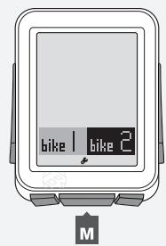
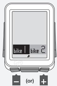
- To change bike1 or bike2, press + or -
- To select, press M.
To go to Ride mode, hold M for three seconds.
(3 sec)
1.

(3 sec)

2.
s2
3.
M
4.
Understanding Your NODE's Functions
SPEED
Speed is a measurement of how fast your bike is moving.
Features of Speed Function
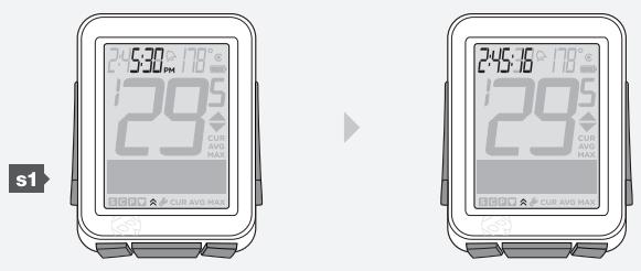
In Ride mode, speed always displays (Figure 10). The NODE can also display your current (CUR), average (AVG), and maximum (MAX) speed. The NODE can do this for two bicycles, bike1 and bike2. Correct display of speed depends on selecting the bicycle before you ride, and on the wheel size setting.
NOTE
Speed Sensor
The sensor for speed is attached to the fork or chainstay of your bicycle. To sense the speed, the speed magnet must be correctly located on a spoke and the wheel must turn.
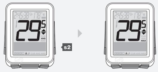
Viewing Speed CUR AVG MAX
- In Ride Mode, scroll s2.
- CUR changes to AVG, which changes to MAX.

Figure 10. Speed Screen.
Cadence is how fast you are pedaling, counted as the number of complete revolutions per minute (RPM) of the crankset.
Features of Cadence Function
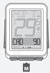
When displaying the cadence function, the lower section of the screen displays CAD (Figure 11). The NODE can display Current (CUR), Average (AVG), and Maximum (MAX) cadence.
NOTE
Cadence Sensor
The sensor for cadence is attached to the left chainstay of your bicycle. The cadence magnet must be correctly located on the crankarm. The sensor must be switched to ON and send a signal.
Viewing Cadence CUR AVG MAX
- In Ride Mode, scroll + to CAD.
2.Scroll M. - CUR changes to AVG, which changes to MAX.
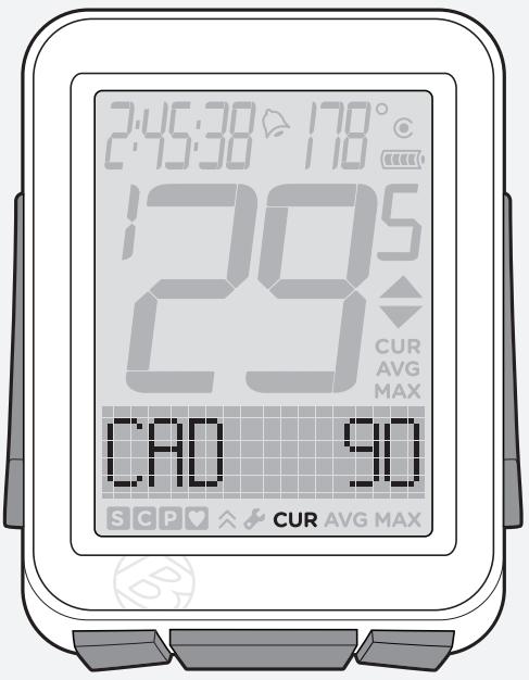
Figure 11. Cadence Function.


1.
2.
3.
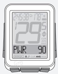
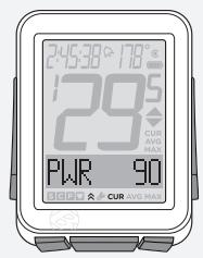
Power is a measurement of the amount of work you are doing, or the horsepower. The metric equivalent of horsepower is joules.
Features of Power Function
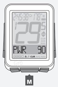
If power data is sent to the NODE, the lower section of the screen displays PWR (Figure 12). The NODE can display Current (CUR), Average (AVG), and Maximum (MAX) power.
NOTE
Power Sensor
The NODE can receive signals from a variety of power meters (sensors) that work with the ANT+ protocol. However, Bontrager does not make a power meter. The sensor must be switched to ON and send a signal (spin the crank).
Viewing Power CUR AVG MAX
- In Ride Mode, scroll + to PWR.
2.Scroll M - CUR changes to AVG, which changes to MAX.
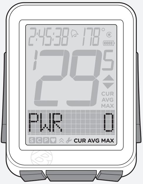
Figure 12. Power Function.
1.
2.
3.
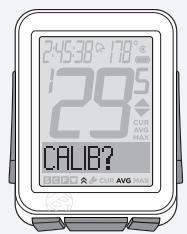
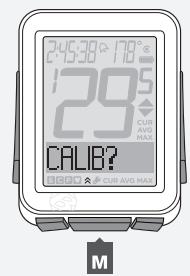
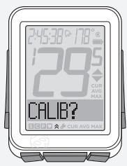
Calibrating Power
To get the most accurate data, you should calibrate the power function before every ride.
- In Ride Mode, scroll + to PWR.
- Press s1.
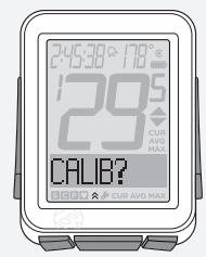
CALIB? (Calibrate?) appears.
s1
1.
2.
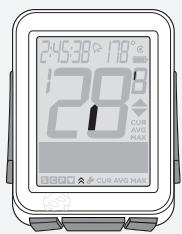
- To calibrate, press M.
As the NODE calibrates, the 0 (zero) of speed flashes each segment in a circular pattern.
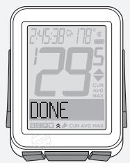
Then DONE (done) appears, and after one second the NODE returns to the PWR function.
3.
NOTE If CALIB? appears, the NODE returns to the calibration screen because the calibration procedure failed. Repeat steps 2 and 3, or see Troubleshooting.
- To return to PWR, press s1.
s1
4.
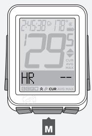
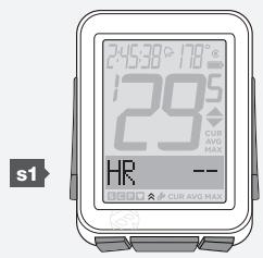
Heart rate is a measurement of the number of times your heart beats in a minute.
Features of Heart Rate Function
If heart rate data is sent to the NODE, the lower section of the screen displays HR (Figure 13). The NODE can display Current (CUR), Average (AVG), and Maximum (MAX) heart rate.
You can also set five zones. Each zone is a target heart rate within an upper and lower limit. The NODE computes the amount of time you have spent in each zone.
NOTE Heart Rate Sensor
The sensor for heart rate is the NODE chest strap. The chest strap must be correctly located on your chest (Figure 14), against your skin, and will work better if the contact area is slightly moist. The chest strap needs to be snug to stay in place. Slide the buckles to adjust the length of the strap. The sensor must be switched to ON and send a signal.
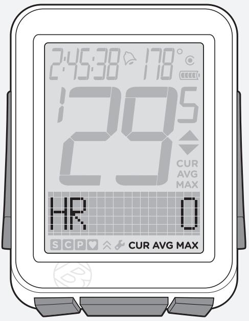
Figure 13. Heart Rate Function.
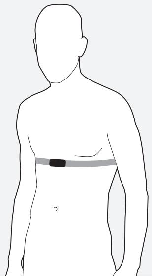
Figure 14. Location for Chest Strap.
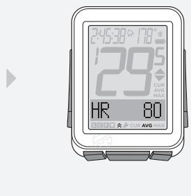
Viewing Heart Rate CUR AVG MAX
- In Ride Mode, scroll + to HR.
2.ScrollM - CUR changes to AVG, which changes to MAX. If you have set the heart rate zones, a number will display beside the CUR heart rate. This number is the current heart rate zone.
1.
2.
3.
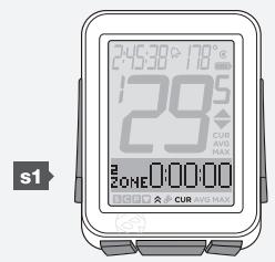
Viewing Zones
The NODE can compute and display the time your heart rate was in each zone.
Before it can collect this data, you must first set the zones.
| Zone | % of Maximum Heart Rate Setting |
| 1 | 50–60 |
| 2 | 60–70 |
| 3 | 70–80 |
| 4 | 80–90 |
| 5 | 90–100 |
- In Ride Mode, scroll + to HR.
- Press s1.
- When CAL appears, press s1 again.

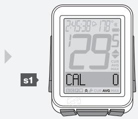
1.
2.
3.
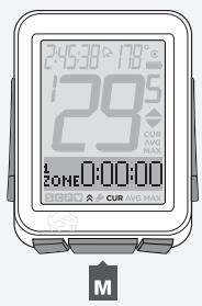
- Zone 1 appears, showing the time spent in Zone 1 since the last Trip Restart.
Scroll M to see Zones 1 through 5.
- To return to HR, press s1.

4.
5.
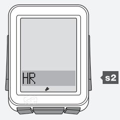
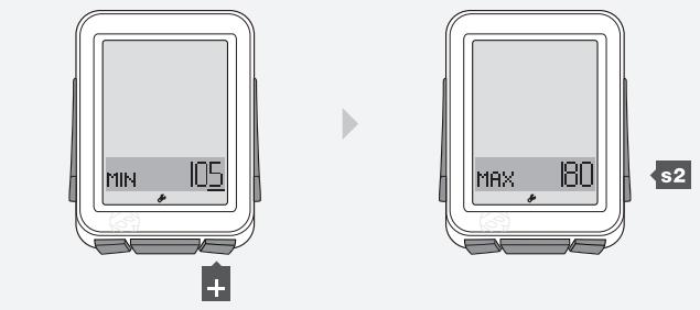
Setting Heart Rate Zones
- Hold M for three seconds to go to Setting mode.
- When BIKES appears, scroll + or - to HR.
- Press s2.

1.
2.
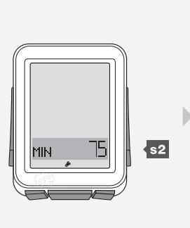
- To change the MIN number, press s2.
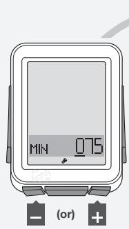
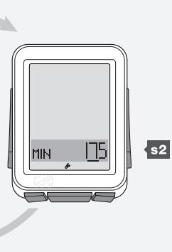
To go to MAX, press + and go to step 6. - To change the underlined digit, press + or -
To select, press s2.
Repeat step 5 for the other digits.
4.
5.
- To go to MAX, press +
- To change the MAX number, press s2.
6.
7.
- To change the underlined digit, press + or -
To select, press s2.
Repeat step 8 for the other digits.
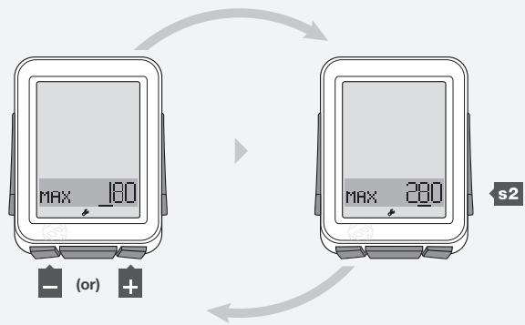
8.
- To save and exit, press M.
To go to Ride mode, hold M for three seconds.
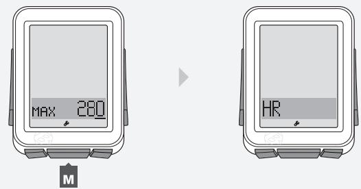
9.
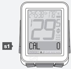
CALORIE OUTPUT (CAL)
This feature estimates the calories you are burning based on work and body weight (Figure 15). CAL is based on heart rate, so the sensor must be switched to ON and send a signal.
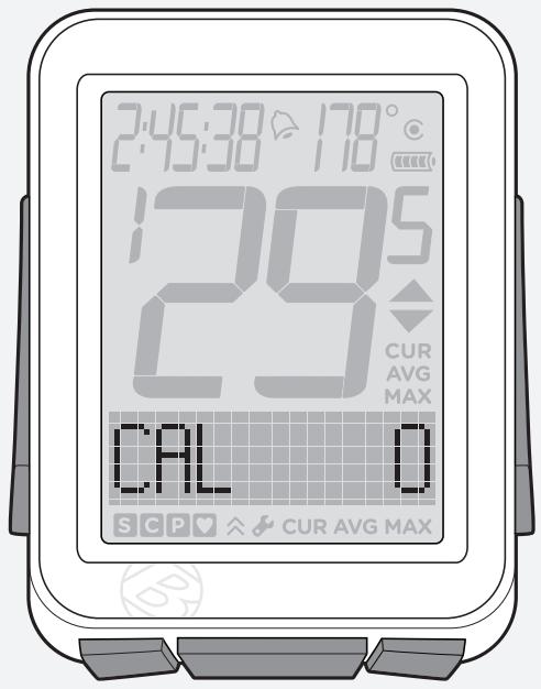
Figure 15. Calorie Output Function.
To View Calorie Output
- In Ride Mode, scroll + to HR.
- Press s1.
- To return to HR, scroll s1.


1.
2.
3.
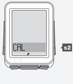
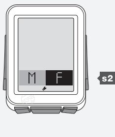
Setting Calorie Output
- Hold M for three seconds to go to Setting mode.
- When BIKES appears, scroll + to CAL.
- Press s2.

(3 sec)

2.
3.
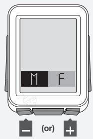
- To change M (male) or F (female), press + or -
- To select, press s2.
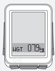
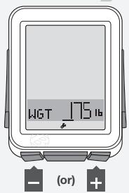
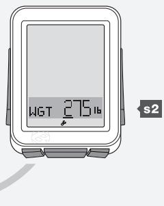
- To change WGT kg or Ib, press + or -
4.
5.
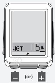
6.
- To select, press $2.
- To change the underlined digit, press + or -
To select, press s2.
Repeat step 8 for the other digits.
5.
7.
8.
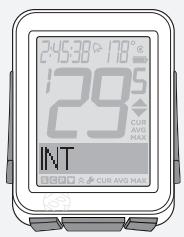
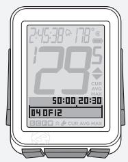
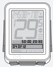
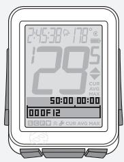
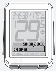
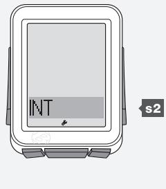
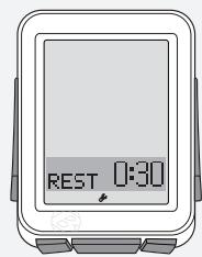
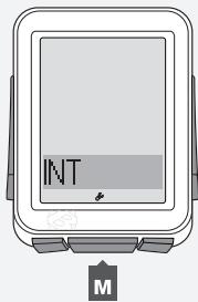
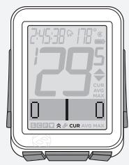
Intervals are periods of time of a set length, separated by set periods of time.
Interval Clock
The interval clock runs separately from the Time function, so you can still use the stopwatch function and scroll through standard functions without stopping the interval clock.
In the INT screen, there are two clocks above a box (Figure 16). When the clock on the left is running, it counts down the time that remains in the interval. When the clock on the right is running, it counts down the time that remains in the rest. The box gives the number of intervals that remain of the total repetitions, and a bar moves across the box to show the relative progress of the interval and rest clocks.
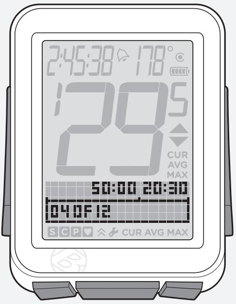
Figure 16. Intervals Function.
To View the Interval Clock
- In Ride Mode, scroll + to INT.
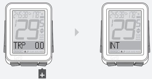
To Start the Interval Clock, or Restart at 0
- In Ride Mode, scroll + or - to INT.
- To start the clock from its current state, press s1.
s1
1.
2.
- To restart the clock at 00:00, hold s1 for three seconds.
s1
3.
To Stop the Interval Clock
- In Ride Mode, scroll + or - to INT.
- Press s1.

s1
1.
2.
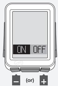
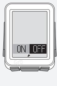
To Set Intervals
Setting intervals has four sections:
ON/OFF (On/Off)
- TIME (the length of time of the interval)
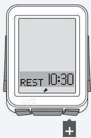
- REST (the length of time between intervals)
- REPS (the number of repetitions)
- Hold M for three seconds to go to Setting mode.
- When BIKES appears, scroll + or - to INT.
-
Press s2.
-
To change from ON or OFF, press + or -
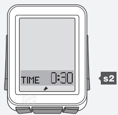
To select, press s2. - To change the Interval time, press s2. To skip to REST, press + and go to step 9.
(3 sec)
2.
3.
4.
5.
6.
7.
- To change the underlined digit, press + or -
To select, press s2.
Repeat step 6 for the other digits. -
To go to REST, press +
-
To change the Rest time, press s2. To skip to REPS, press + and go to step 13.
- To change the underlined digit, press + or - .
To select, press s2.
Repeat step 9 for the other digits.
s2

(or)
s2
8.
9.
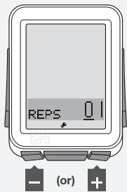
- To go to REPS, press +
- To change the number of repetitions, press s2.
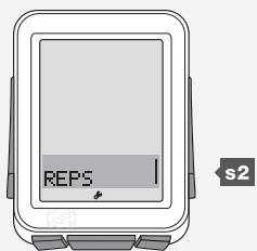
10.
11.
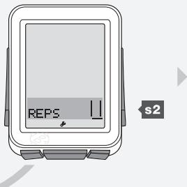
- To change the underlined digit, press + or -
To select, press s2.
Repeat step 12 for the other digits.
- To save and exit, press M.
To go to Ride mode, hold M for three seconds.
12.
13.
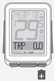
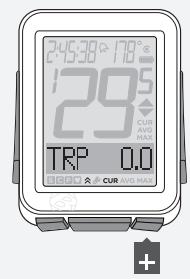
TRIP (TRP)
Trip is the distance you have traveled since the last Trip Restart. Odometer is the distance since the last Reset (erase of settings). The NODE adds distance values of Trip and Odometer from bike1 to those of bike2.
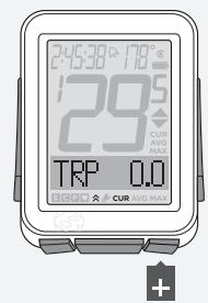
Features of Trip Function
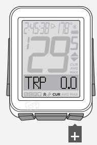
In Trip, the lower section of the screen displays TRP (Figure 17). If the display shows the odometer, there are no letters displayed.
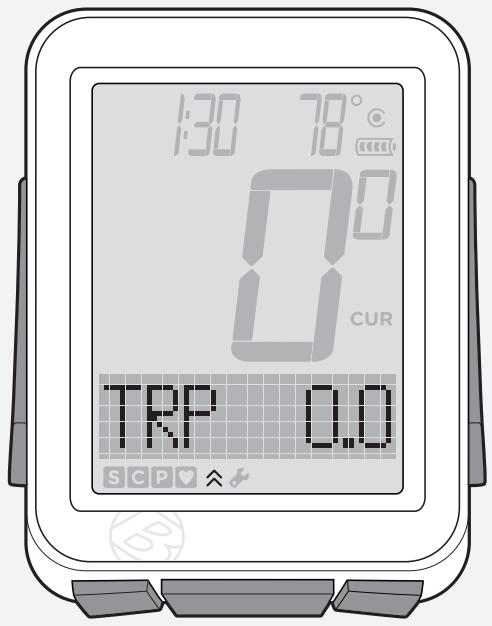
Figure 17. Trip Function.
NOTE Sensor for Trip Data
The speed sensor collects distance for the trip data. To sense the passing of the wheel magnet, the speed sensor must be correctly located.
Viewing Trip (TRP) and Odometer
- In Ride Mode, scroll + to TRP.
- Toggle s1.
The display changes from TRP to odometer (no screen abbreviation).
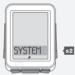
Setting the Odometer
- Hold M for three seconds to go to Setting mode.
- When BIKES appears, scroll + to SYSTEM.
- Press s2.
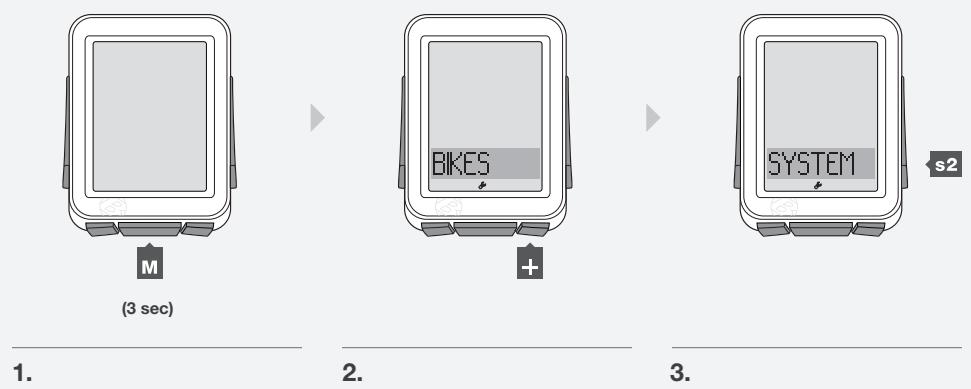
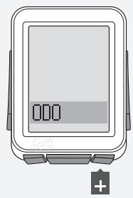
- When ODO appears, press s2.
- To change the underlined digit, press + or -
To select, press s2.
Repeat step 5 for the other digits.
To go to Ride mode, hold M for three seconds.
4.
5.
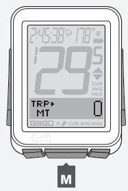
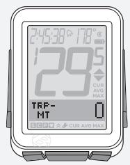
The NODE 2 can calculate ALT, or altitude. Altitude is the height above sea level. The NODE adds altitude values from bike1 to those of bike2.
Features of Altitude Function
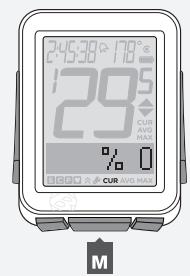
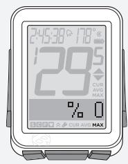
The altitude function can calculate changes in altitude during a ride, including loss, gain, and total change (Figure 18). The altitude function can also calculate the current and maximum grade, the percent of climbing over a distance.

Figure 18. Altitude Function.
To View Grade (%), Trip (TRP), and Total (TTL)
MT = meters
FT = feet
- In Ride Mode, scroll + to ALT.
2.Scroll s1.
Grade (%) appears, then Trip altitude (TRP+) appears, then Total altitude (TTL+) appears.
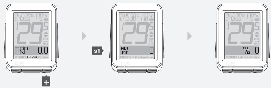
- To see the gain (+) or loss (-) in Trip or Total, scroll to that feature and toggle M.
3.
- When % appears, toggle M to see current (CUR) and maximum (MAX).
4.
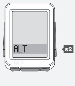
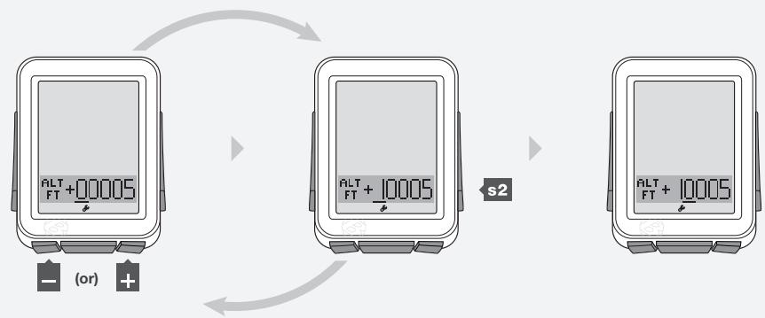
Setting Current Altitude
The altimeter measures your altitude based on air pressure and temperature. Air pressure changes with the weather, so for the best accuracy you should set the current altitude before your first use and again whenever you are near a point of reference of known altitude.
- Hold M for three seconds to go to Setting mode.
- When BIKES appears, scroll + or - to SYSTEM.
- Press s2.
1.
2.
3.
- When ODO appears, scroll + to ALT.
- Press s2.
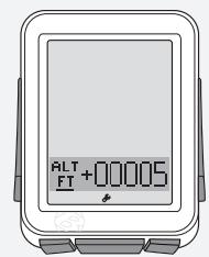
- To change from FT or MT, press + or -
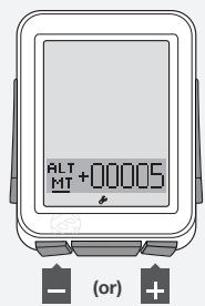
4.
5.
6.
To select, press s2.
- To change from + or - , press + or - .
To select, press s2.
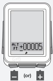
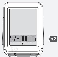
7.
- To change the underlined digit, press + or -
To select, press s2.
Repeat step 8 for the other digits.
To go to Ride mode, hold M for three seconds.
8.
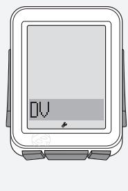
DUAL VIEW (DV)
Dual View splits the lower screen to show two of the secondary functions simultaneously (Figure 19). Speed, the primary function, always displays in Ride mode. With Dual View, in addition to Speed, your NODE can also display, for example, Power and Heart Rate.
There are four functions available in Dual View:
HR (Heart Rate)
- TRP (Distance)
- CAD (Cadence)
PWR (Power)
In order for these functions to be available in Dual View, they must switched ON, Paired, and Connected. (See "Pairing Procedure," "Connecting Procedure," and "Switching Sensors to OFF or ON" above.)
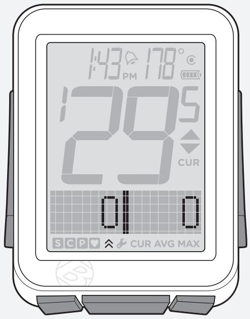
Figure 19. Dual View Function.
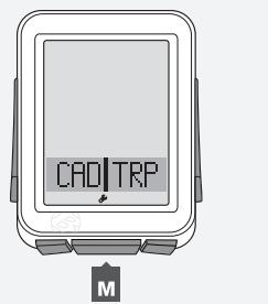
To Turn the Dual View Function On, Configure Display
- Hold M for three seconds to go to Setting mode.
- When BIKES appears, scroll + or - to DV.
- Press s2.
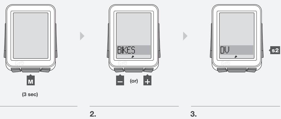
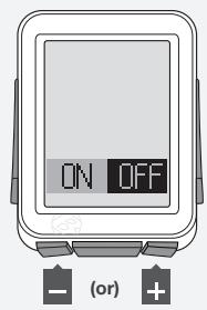
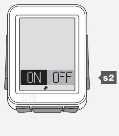
- To change to ON or OFF, push + or -
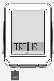
To select, press s2. - To change the function on the left, scroll
4.
5.
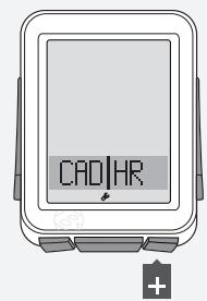
- To change the function on the right, scroll +
- To save and exit, press M.
To go to Ride mode, hold M for three seconds.
6.
7.
To View Dual View (DV)
- In Ride mode, scroll + to DV.
1.
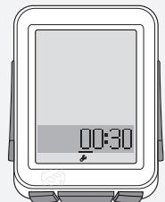
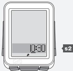
TIME
The NODE works with time in two ways:
Time of Day (clock) HH:MM hours and minutes
- Ride time (stopwatch) HH:MM:SS, hours, minutes, and seconds
In Ride mode, the time function always displays (Figure 20).
Ride time data is erased in a Trip Restart, but the Clock setting is not. When the Ride Time clock goes past 9:59:59, the first digit changes to show an H along with hours and minutes ( H:00:00 ).
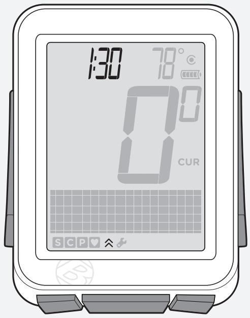
Figure 20. Time Function.
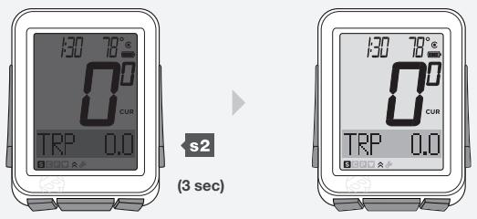
Viewing Clock and Ride Time
- In Ride mode, hold s1 for three seconds to toggle Clock and Ride Time.
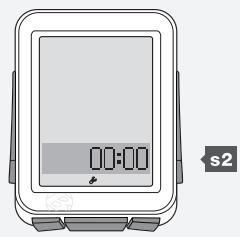
Setting Time
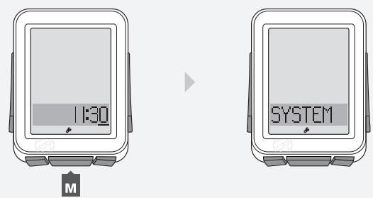
- Hold M for three seconds to go to Setting mode.
- When BIKES appears, scroll + or - to SYSTEM.
- Press s2.

1.
2.
3.
- When ODO appears, scroll + to CLOCK.
- To change, press s2.
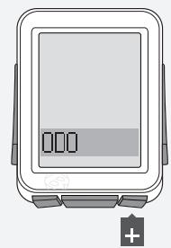
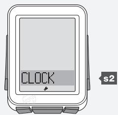
4.
5.
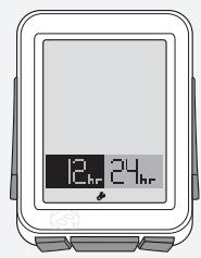
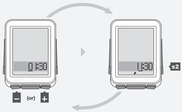
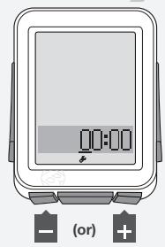
- To change 12hr or 24hr, press + or -
To select, press s2.
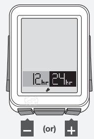
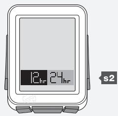
6.
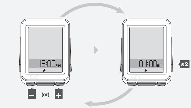
- To change the underlined digit, press + or -
To select, press s2.
Repeat step 7 for the other digits.
If you selected the 12hr clock, you also must select AM or PM.
7.
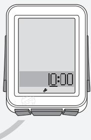
- To save and exit, press M.
To go to Ride mode, hold M for three seconds.
8.
NUTRITION TIMER
The nutrition alarm displays an alarm bell (Figure 21) to remind you to eat at intervals you select. The intervals are based on the ride time clock, not the time of day, so the nutrition timer shows time as hours and minutes (HH:MM).
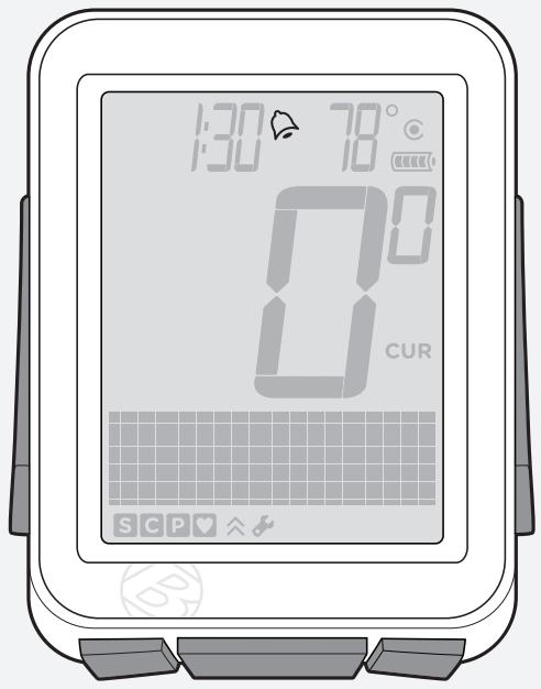
Figure 21. Nutrition Timer Alarm.
Setting Nutrition Alarm
- Hold M for three seconds to go to Setting mode.
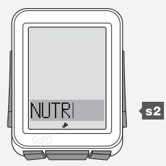
- When BIKES appears, scroll + to NUTRI.
Press s2.
(3 sec)
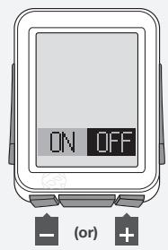
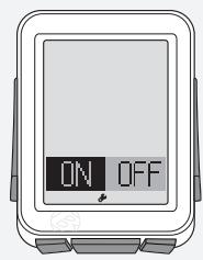
- To change ON or OFF, press + or -
To select, press 2. - Press s2 again.
s2
3.
4.
s2
- To change the underlined digit, press + or -
To select, press s2.
Repeat step 5 for the other digits.
To go to Ride mode, hold M for three seconds.
5.
BACKLIGHT
The NODE 2 has a screen backlight. The backlight provides a light source behind the screen so that the numbers are more visible.
To Switch the Backlight to ON
- In Ride mode, hold s2 for three seconds.
To save battery life, the backlight automatically switches to Off after five seconds.
Installation
This section explains how to attach the computer to the handlebar and attach the sensors and magnets to their locations. There are no wires.
Tools Required
- Screwdriver, small slot type
- Screwdriver, small phillips type
- 2.5mm allen key (if installing a SpeedTrap or DuoTrap sensor)
To Attach the Computer to the Handlebar
- Determine the diameter of your handlebar (25.4 mm, 26.0 mm, or 31.8 mm).
- Insert the correct clasp into the computer base (Figure 22).
- Slide the head of the clasp to the end of the slot in the base.
- Insert the rubber pad with logo into the back of the base (Figure 23).
- Wrap the clasp around the handlebar.
- From the front side of the computer, insert the screw and tighten (Figure 24).
- Slide the computer head into the base (Figure 25).
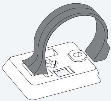
Figure 22. Clasp in the Back of Computer Base.
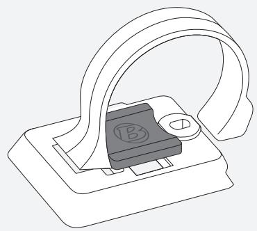
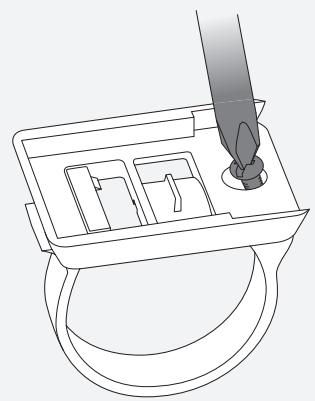
Figure 23. Pad Inserted in Computer Base.
Figure 24. Tighten Screw.
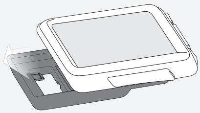
Figure 25. Slide Computer into Base.
To Attach the Computer to the Stem
- Insert the rubber pad with logo into the back of the computer base.
- Position the base on the stem.
- Secure the base to stem using zip-ties.
- Slide the computer head into the base (Figure 25).
To Install the Speed Magnet
- With the logo facing away from the wheel (Figure 26), wrap the magnet around a spoke.
- Close the magnet so that the spoke is in the tunnel through the magnet (Figure 27). Squeeze the magnet until the clasp is engaged.
- Slide the magnet up or down the spoke to align it with the sensor (Figure 28).
- Tighten the clamp screw on the back of the magnet (Figure 29) to secure the position of the magnet.
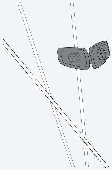
Figure 26. Magnet on Spoke.
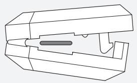
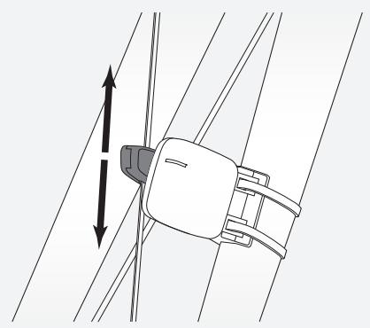
Figure 27. Spoke Slot and Clasp.
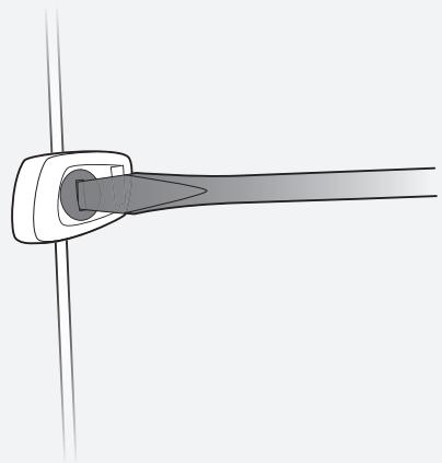
Figure 28. Alignment of Magnet.
Figure 29. Tighten the Clamp Screw.
To Install the Cadence Magnet
- Remove the left pedal.
- Slide the cadence magnet (Figure 30) onto the crankarm with the magnet to the inside.
- Reinstall the pedal.
- Align the magnet with the cadence sensor.
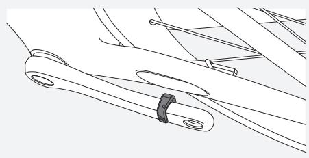
Figure 30. Crank Magnet on Crank Arm.
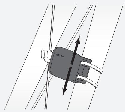
Figure 31. Speed Sensor on Fork.
To Install the Sensor(s)
Certain Trek and Gary Fisher road bikes feature a specially designed pocket that allows you to integrate a SpeedTrap sensor directly into the fork leg or a DuoTrap (Figure 32) sensor directly into the chainstay. If installing a SpeedTrap or DuoTrap sensor (both sold separately), please refer to the installation instructions included with the sensor.
For non-SpeedTrap or DuoTrap compatible bikes:
- Position the sensor on the fork leg (Figure 31) or chainstay to achieve the correct alignment with the magnet (Figure 28). If needed, move the magnet.
- When you have achieved the correct alignment, pass a zip-tie through the sensor and around the fork blade or chainstay (Figure 33).
- Install a second zip-tie.
- Re-check the alignment of the sensor, and tighten both zip-ties.
- Using a pair of scissors, cut off the excess length of zip-tie.
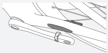
Figure 32. DuoTrap Sensor in Chainstay.
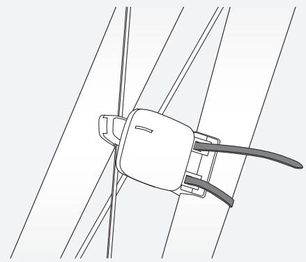
Figure 33. Zip-tie.
Battery Maintenance
There is a battery in the computer, and also in each of the sensors. If you use the NODE for one hour every day, the batteries should last about 10 months.
Sensor Batteries
Replace the batteries in the sensors every 10 months, or whenever the computer cannot perform the Pair or Connect procedure with a given sensor (Figure 34).
Computer Battery
Replace the battery in the computer when the battery indicator gets to 10% (when the indicator shows no bars). Before removing the computer battery, note the Trip and Total values. When the battery is removed, the computer automatically does a Reset (erase settings) and changes function totals to zero (0). After installing a new battery (Figure 35), you can manually set your totals.
Battery Type
The same battery type is used for the computer and each sensor, a 3-volt CR2032 lithium cell. When you go to the store, take the old battery with you.
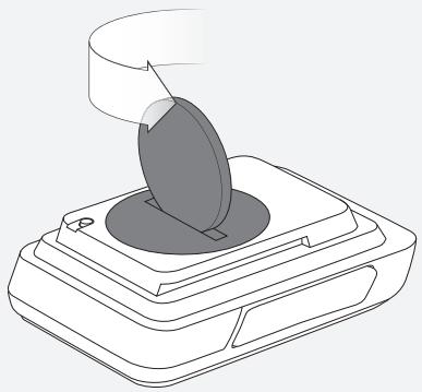
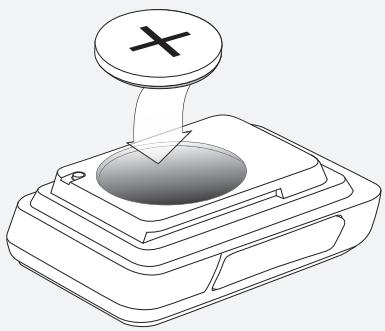
Figure 34. Removing the Battery Cover.
Figure 35. Battery Replacement.
Reset
You can erase all settings and programming. Push the Reset button (Figure 36).
The NODE goes to the procedure for Automatic Setup.
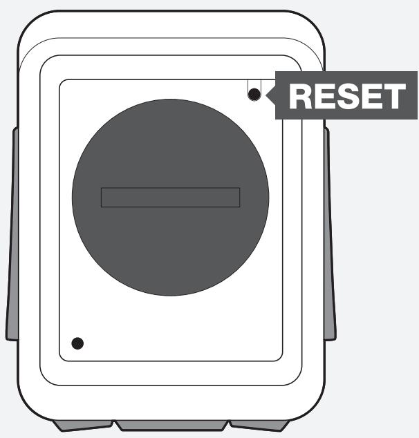
Figure 36. Reset Button.
If your NODE computer has problems, use this guide to fix it. If you cannot fix it, take your computer—with the bicycle—to your dealer.
Symptom
Possible Causes
Solution
| Erratic data | Magnet misaligned or too far away | Readjust magnet and sensor placement |
| Sensor battery power is low | Replace battery | |
| No current speed | Magnet misaligned or too far away | Readjust magnet and sensor placement |
| Sensor is switched to OFF | Switch sensor to ON | |
| Computer is not connected to sensor signal | Force connect | |
| Speed is incorrect | Wheel size is incorrect | Reset (erase settings) computer |
| Sensor is not reading magnet properly | Readjust magnet and sensor alignment | |
| Sensor battery power is low | Replace battery | |
| No cadence | Sensor is not reading magnet properly | Readjust magnet and sensor alignment |
| Computer is not connected to sensor signal | Force connect | |
| Sensor battery power is low | Replace battery | |
| Sensor is switched to OFF | Switch sensor to ON | |
| No heart rate | Sensor is not reading heart rate properly | Readjust or moisten heart rate strap |
| Computer is not connected to sensor signal | Force connect | |
| Sensor battery power is low | Replace battery | |
| Sensor is switched to OFF | Switch sensor to ON | |
| Power does not calibrate | Computer is not connected to sensor signal | Force connect |
| Sensor battery power is low | Replace battery | |
| Sensor is switched to OFF | Switch sensor to ON | |
| Sensor not sending signal | Refer to owner's manual for power meter | |
| Blank screen | Computer is in shipping mode | Hold the M button for three seconds |
| Battery is dead, or installed incorrectly | Reinstall good battery | |
| -- displays | No sensors signals are connected | Activate the sensors and Force connect |
www.bontrager.com
Bontrager & Bontrager B-Dot are registered trademarks of Trek Bicycle Corporation.
©2009 Trek Bicycle Corporation, Waterloo, Wisconsin 53594 USA. All rights reserved.
Part Number 304105