
F3S-TGR-SB - Capteur de sécurité OMRON - Notice d'utilisation et mode d'emploi gratuit
Retrouvez gratuitement la notice de l'appareil F3S-TGR-SB OMRON au format PDF.


| Marque | OMRON |
| Modèle | F3S-TGR-SB |
| Type de produit | Capteur de sécurité multi-faisceaux pour palettiseurs |
| Catégorie de sécurité | Type 4 (F3S-TGR-SB4) ou Type 2 (F3S-TGR-SB2) selon modèle |
| Nombre de faisceaux | 2, 3 ou 4 selon modèle |
| Portée | 0,5 à 6 m |
| Pas de faisceau | 500 mm (2 faisceaux), 400 mm (3 faisceaux), 300 mm (4 faisceaux) |
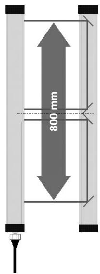
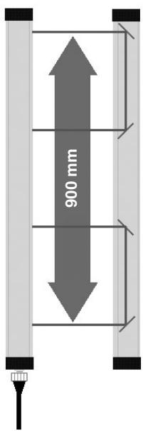
| Écartement des faisceaux extrêmes | 500 mm (2 faisceaux), 800 mm (3 faisceaux), 900 mm (4 faisceaux) |
| Alimentation électrique | 24 VDC ± 20 % |
| Consommation | 420 mA |
| Sorties OSSD | Deux sorties PNP, 250 mA chacune (500 mA total) |
| Temps de réponse | ON à OFF : 16 ms max ; OFF à ON : 300 ms max |
| Indice de protection | IP65 |
| Température ambiante | -10 à +55 °C |
| Humidité ambiante | 15 % à 95 % (sans condensation) |
| Matériau du boîtier | Aluminium peint, jaune RAL 1303 F14 |
| Fonctions intégrées | Muting, override, test/reset, interlock, lampe de muting |
| Accessoires inclus | 8 vis à tête T M6, 8 écrous M6, 4 supports de montage |
| Normes applicables | EN61496-1, EN61496-2, EN954-1 (catégories 4, 3, 2, 1, B) |
| Boîte de connexion de muting (optionnelle) | F39-TGR-SB-CMB1 ou CMB2, IP65, 0,5 kg |
| Lampe de muting (optionnelle) | F39-A11, 24 VDC |
| Kit d'alignement laser (optionnel) | F39-LKK2-SB |
| Nettoyage et entretien | Nettoyer avec un chiffon sec et non abrasif. Ne pas utiliser de solvants. |
| Réparabilité | Pièces de rechange disponibles : lampes, connecteurs, câbles. Contacter le service après-vente OMRON. |
FOIRE AUX QUESTIONS - F3S-TGR-SB OMRON
Questions des utilisateurs sur F3S-TGR-SB OMRON
0 question sur cet appareil. Repondez a celles que vous connaissez ou posez la votre.
Poser une nouvelle question sur cet appareil
Téléchargez la notice de votre Capteur de sécurité au format PDF gratuitement ! Retrouvez votre notice F3S-TGR-SB - OMRON et reprennez votre appareil électronique en main. Sur cette page sont publiés tous les documents nécessaires à l'utilisation de votre appareil F3S-TGR-SB de la marque OMRON.
MODE D'EMPLOI F3S-TGR-SB OMRON
Safety sensor for Palletisers
F3S-TGR-SB□C series

natural_image
Three black rectangular metal bars with reflective surfaces, arranged diagonally (no text or symbols visible)
TECHNO GR OPTIC SENSORS
Features
For Palletiser
F3S-TGR-SB□C series has been developed especially for Palletisers and wrapping machine access protection applications.
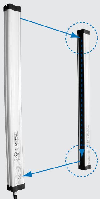
Active - Passive system and Plug and play
By using a mirror system we can achieve an active - passive multi beam system. This active passive system will improve installation time and reduce costs.
3 Different types available
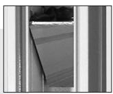
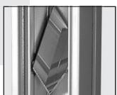
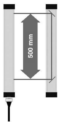
We provide 3 different Types as following:
• 2 beam Type (beam pitch 500 mm)
• 3 beam Type (beam pitch 400 mm)
• 4 beam Type (beam pitch 300 mm)
Muting functions are integrated
Following Muting functions are integrated:
- Muting sensor inputs
- Muting Lamp output
- Override input (120 second max)
- Test / Reset input
- Interlock function and Test Reset input
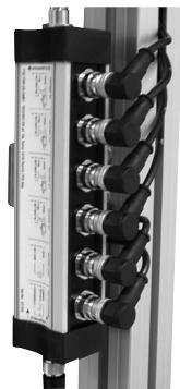
Decentralized Muting connection Box
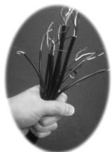
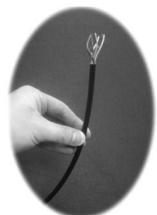
Furthermore, using a F39-TGR-SB-CMB1, it's possible to reduce the wiring time and wiring material for the muting Sensors and Muting Lamp etc.
Ex. 1
Ex. 2
In the conventional solution all wires from the light curtain, mute sensors, lamp, reset are wired back to the mute controller in the control cabinet (See Ex. 1) As you can see this solution need JUST ONE WIRE to the cabinet (See Ex. 2)
To Barrier
natural_image
Close-up of a black industrial control panel with coiled black connectors (no visible text or symbols)To Cabinet
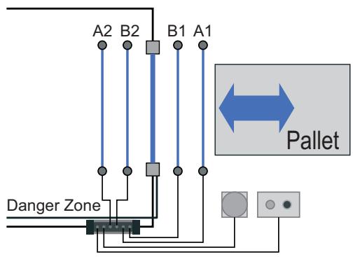
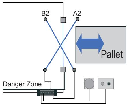
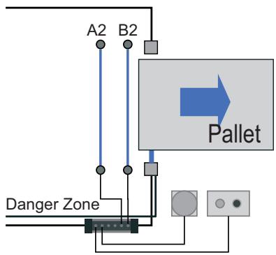
Multiple mute connections are possible
- PARALLEL MUTING and TWO WAY direction
- CROSS MUTING and TWO WAY direction
flowchart
graph TD
    A["Danger Zone"] --> B["Switch"]
    B --> C["A2"]
    B --> D["B2"]
    C --> E["Pallet"]
    D --> E
    E --> F["Output"]
- PARALLEL MUTING and ONE WAY direction
flowchart
graph TD
    A["Danger Zone"] --> B["A2"]
    A --> C["B2"]
    B --> D["Pallet"]
    C --> D
    D --> E["Control Point"]
    style A fill:#f9f,stroke:#333
    style B fill:#ccf,stroke:#333
    style C fill:#cfc,stroke:#333
    style D fill:#ffc,stroke:#333
    style E fill:#cff,stroke:#333
Please add MTL*. Ex. F3S-TGR-SB4-K1CMTL
- CROSS MUTING and ONE WAY direction
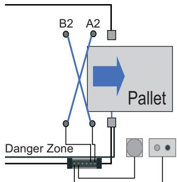
flowchart
graph TD
    A["Danger Zone"] --> B["A2"]
    B --> C["Pallet"]
    C --> D["B2"]
    style A fill:#f9f,stroke:#333
    style C fill:#ccf,stroke:#333
    style D fill:#cfc,stroke:#333
Please add MTL*. Ex. F3S-TGR-SB4-K1CMTL
Reference

Muting Lamp

Override and Test Switch

F3S-TGR-SB□-K□C
- Muting sensor

F3S-TGR-SB-CMB□
Mechanical Guard
*MTL has a special software inside of F3S-TGR-SB□C which works to finalize a Muting function.
Muting Sensors Recommendation
It is recommended to use the E3Z or E3G as muting sensor. Please refer to the E3Z datasheet Cat.No. E701-E2-Cat04-01 and the E3G datasheet Cat.No. E278-E2-Cat04-03.
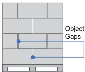
SOLUTION 1: Object Gaps
In many palletiser applications there is a gap between objects on the pallet. The Muting function may not work correctly because of this gap. To avoid the mutual interruption, we recommend to Use E3G□□□□T as muting sensor. E3G-□□□□T has ON delay timer internally (0 to 5 seconds)
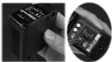
SOLUTION 2: Misalignment of pallets
When using a CROSS MUTING system, It may cause that unexpected behavior when the pallets get out of alignment then E3G□□□□T also solves the problem by OFF delay
natural_image
Close-up of hands holding a black electronic device with a close-up view showing its internal components (no visible text or symbols)Safety Multi beam Sensors
F3S-TGR-SB2-K□C Mirror Reflection Type (Type 2)
| Shape | Number of optical axes | Sensing Distance | Beam Pitch | Model |
 | 2 | 0.5 to 6 m | 500 | F3S-TGR-SB2-K2C-500(MTL)* |
| 3 | 0.5 to 5 m | 400 | F3S-TGR-SB2-K3C-800(MTL)* | |
| 4 | 300 | F3S-TGR-SB2-K4C-900(MTL)* |
*. If you want to have a ONE WAY direction Type, (see Page D-26) Please add the MTL behind of Model Name. Ex. F3S-TGR-SB4-K2C-500MTL
F3S-TGR-SB4-K□C Mirror Reflection Type (Type 4)
| Shape | Number of optical axes | Sensing Distance | Beam Pitch | Model |
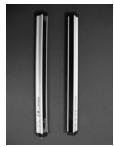 | 2 | 0.5 to 6 m | 500 | F3S-TGR-SB4-K2C-500(MTL)* |
| 3 | 0.5 to 5 m | 400 | F3S-TGR-SB4-K3C-800(MTL)* | |
| 4 | 300 | F3S-TGR-SB4-K4C-900(MTL)* |
*. If you want to have a ONE WAY direction Type, (see Page D-26) Please add the MTL behind of Model Name. Ex. F3S-TGR-SB4-K2C-500MTL
Muting Connecting Box (Order Separately)
Flexible Connecting Box
| Appearance | SLC Connection Type | Other connection | Model |
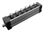 | M12 8pin connector without cable | 4 x Muting sensor connection (4pin)1 x Muting Lamp M12 (4pin)1 x Override/Test input M12 (4pin)1 x cabinet connection M12 (8pin) | F39-TGR-SB-CMB1 |
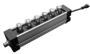 | M12 8pin connector with 100 mm cable | F39-TGR-SB-CMB2 |
Accessories (Order Separately)
Connector Cable
| Appearance | Cable length | Specification | Model |
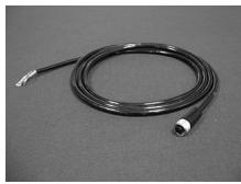 | 2 m | M12 connector (8pin Socket)For cabinet connection(From F3S-TGR-SB□-K□C or F3S-TGR-SB-CMB□) | F39-TGR-SB4-CVLB2R |
| 5 m | F39-TGR-SB4-CVLB5R | ||
| 10 m | F39-TGR-SB4-CVLB10R | ||
 | 2 m | M12 connector (4pin Plug)For Muting sensor, Muting Lamp connection and Override/Test connection | F39-TGR-SB4-CVLB2MC |
Connector Plug Assemblies, Screw-on Type
| Appearance | Cable connection direction | Specification | Connection method | Applicable cable diameter | Model |
 | Straight | DC only 4pin Plug | Screw-on | 3 dia. (3 to 4 dia.) | XS2G-D4S5 |
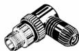 | Right angle | XS2G-D4S6 |
Muting Lamp
| Appearance | Specification | Model |
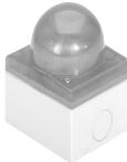 | 24 V DC | F39-A11 |
Bulb for Maintenance
| Appearance | Specification | Model |
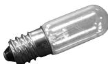 | 24 V DC 3 W E14 | F39-A11MB |
Laser alignment Kit
| Appearance | Model |
 | F39-LKK2-SB |
Safety sensors
F3S-TGR-SB□-K□C
| Item | Model | |
| F3S-TGR-SB4-K□C-□□□(MTL)* | F3S-TGR-SB2-K□C-□□□(MTL)* | |
| Sensor type | Type 4 | Type 2 |
| Applicable safety category | 4, 3, 2, 1, B | 2, 1, B |
| Operating range | F3S-TGR-SB□-K2C 0.5 - 6 mF3S-TGR-SB□-K3C/K4C 0.5 - 6 m | |
| Beam pitch and Number of beam | F3S-TGR-SB□-K2C 500 mm 2 beam with mirrorF3S-TGR-SB□-K3C 400 mm 3 beam with mirrorF3S-TGR-SB□-K4C 300 mm 4 beam with mirror | |
| Outermost beam gap | F3S-TGR-SB□-K2C 500 mmF3S-TGR-SB□-K3C 800 mmF3S-TGR-SB□-K4C 900 mm | |
| Effective aperture angle (EAA) | Within ±2.5° | Within ±5° |
| Light source | Infrared LED (880 nm) | |
| Power supply | 24 VDC ± 20% | |
| Current Consumption | 420 mA | |
| OSSD | Two PNP transistor outputs, 250 mA each. (500 mA sum) | |
| Output operation mode | Light - ON | |
| Test functions | Self-test (after power ON and during operation, one cycle during response time) | |
| Protection | Output short-circuit protection, Reverse Polarity protection | |
| Response time | ON to OFF 16ms maxOFF to ON 300 ms (Maximum Power-ON time is 900 ms) | |
| Ambient temperature | Operating: -10 to +55 °C (with no dew condensation) | |
| Ambient humidity | 15% to 95% (non condensing) | |
| Metal housing (Al) painted | Yellow (RAL 1303 F14) | |
| Degree of protection | IP65 | |
| Accessories | M6 T-Bolt x 8, M6 Nut x 8Mounting fixture x 4 | |
| Applicable standards | EN61496-1; 1997prEN61496-2; 1997 | |
*. If you want to have a ONE WAY direction Type, (see Page D-26) Please add the MTL behind of Model Name. Ex. F3S-TGR-SB4-K2C-500MTL
Muting Connecting Box
F3S-TGR-SB-CMB□
| Item | Model | F39-TGR-SB-CMB□ |
| Power supply | 24 VDC ± 20% | |
| Consumption | 10 W max | |
| Ambient temperature | During operation: -10 to +55 °C (with no dex condensation) | |
| Ambient humidity | 15% to 95% (non condensing) | |
| RX connector | M12 8 pins female | |
| Cabinet connector | M12 8 pins male | |
| Sensor connector | 4 x M12 4 pins female | |
| Muting indicator | M12 4 pins female | |
| Test / Override connectors | M12 4 pins female | |
| Metal housing (Al) painted | Yellow (RAL 1303 F14) | |
| Degree of protection | IP65 | |
| Material | Case | Aluminium |
| Connector | Brass with nickel plate | |
| Front Cover | Aluminium | |
| Weight | 0.5 kg | |
| Accessories | M6 T-Bolt x 4, M6 Nut x 4Mounting fixture x 2, Connector cover x 2 | |
| Applicable standards | 93/68/EECDIN V VDE 0801:1990 and am.A1:1994EN 50081-2:1993EN 55022:1998 | |
Dimensions
F3S-TGR-SB-K□C-□□□ with Mounting Brackets
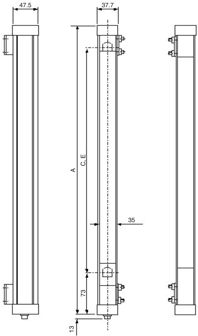
| Model | A | C | E |
| F3S-TGR-SB□-K2C500 | 614 mm | 500 mm | 500 mm |
| F3S-TGR-SB□-K3C800 | 914 mm | 800 mm | 400 mm |
| F3S-TGR-SB□-K4C900 | 1,014 mm | 900 mm | 300 mm |
F39-TGR-SB-CMB1
Muting connection box
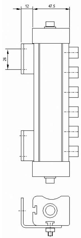
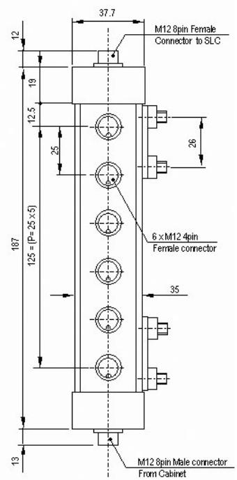
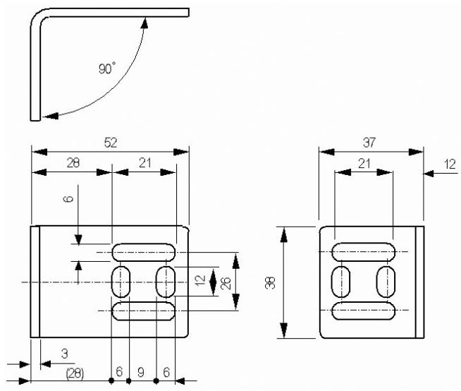
Mounting bracket (Common bracket for F3S-TGR-SB□-K□C and F39-TGR-SB-CMB□
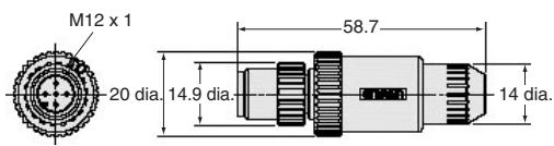
Connector Plug Assemblies, Screw-on Type
XS2G-D4S5
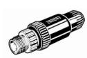
XS2G-D4S6
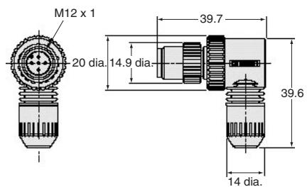
F3S-TGR-SB□-K□C
Connection example
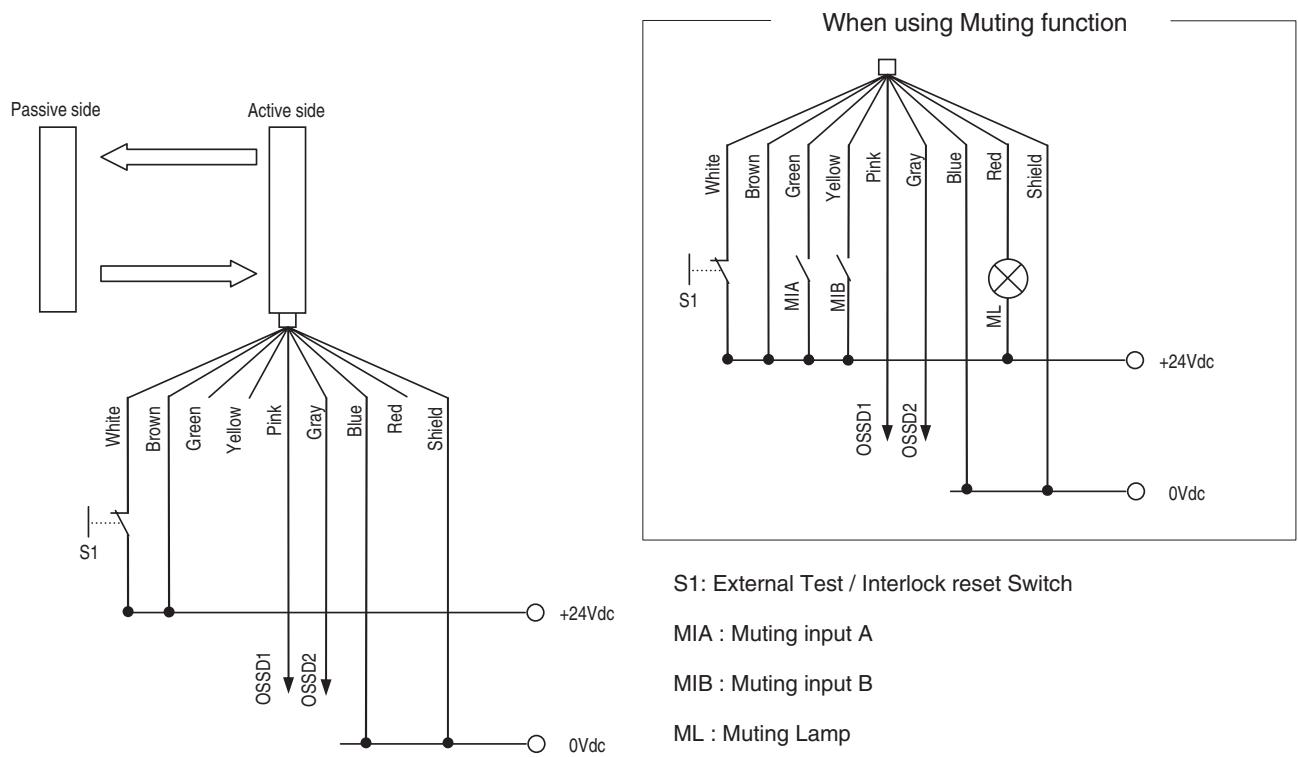
S1: External Test / Interlock reset Switch
MIA : Muting input A
MIB : Muting input B
ML : Muting Lamp
In case of Cat 4 (EN954-1), OSSD1/2 must be connected Safety Relay Unit (G9SA, G9SB-301B etc.) with feedback monitor
Pin reference
| Front View | Pin No. | Signal Name | Wire Color |
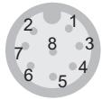 | 1 | Test and Reset Input | White |
| 2 | +24 Vdc | Brown | |
| 3 | Muting A Input | Green | |
| 4 | Muting B Input | Yellow | |
| 5 | OSSD1 (OUT1) | Gray | |
| 6 | OSSD2 (OUT2) | Pink | |
| 7 | 0 Vdc | Blue | |
| 8 | Muting Lamp (0 Vdc) | Red |
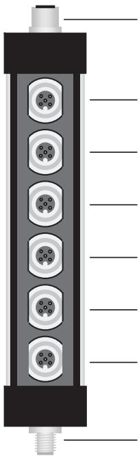
F3S-TGR-SB-CMB□
Pin and Plug reference
natural_image
Cross-sectional diagram of a vertical mechanical or electrical component with six circular components mounted on a base (no text or symbols)1) To Barrier (F3S-TGR-SB series)
M12 8pin connector (Female) *1
2) Muting Sensor B2
M12 5pin connector (Female)
3) Muting Sensor A2
M12 5pin connector (Female)
4) Muting Sensor B1
M12 5pin connector (Female)
5) Muting Sensor A1
M12 5pin connector (Female)
6) Muting Lamp
M12 5pin connector (Female)
7) Test/Override
M12 5pin connector (Female)
8) From Cabinet
M12 8pin connector (Male)
*1 In case of F3S-TGR-SB-CMB2, M12 8pin connector with 100 mm cable
1) To F3S-TGR-SB Series
| Front View | Pin No. | Signal Name | Wire Color |
 | 1 | Test and Reset Input | White |
| 2 | +24 Vdc | Brown | |
| 3 | Muting A Input | Green | |
| 4 | Muting B Input | Yellow | |
| 5 | OSSD1 (OUT1) | Gray | |
| 6 | OSSD2 (OUT2) | Pink | |
| 7 | 0 Vdc | Blue | |
| 8 | Muting Lamp (0 Vdc) | Red |
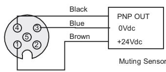
2), 3) 4), 5) Wiring of Muting Sensor connection
| Front View | Pin No. | Signal Name | Wire Color |
 | 1 | +24 Vdc | Brown |
| 2 | No connect | White | |
| 3 | 0 V | Blue | |
| 4 | PNP Input | Black |
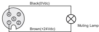
6) Wiring of Muting Lamp connection
| Front View | Pin No. | Signal Name | Wire Color |
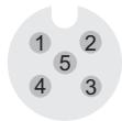 | 1 | +24 Vdc | Brown |
| 2 | No connect | White | |
| 3 | No connect | Blue | |
| 4 | 0 V | Black |
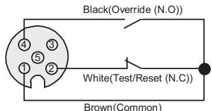
7) Test/Override connection
| Front View | Pin No. | Signal Name | Wire Color |
 | 1 | +24 Vdc | Brown |
| 2 | Test input | White | |
| 3 | No connect | Blue | |
| 4 | Override input | Black |
8) From Cabinet
| Front View | Pin No. | Signal Name | Wire Color |
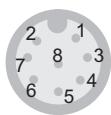 | 1 | Test and Reset Input | White |
| 2 | +24 Vdc | Brown | |
| 3 | Muting A Input | Green | |
| 4 | Muting B Input | Yellow | |
| 5 | OSSD1 (OUT1) | Gray | |
| 6 | OSSD2 (OUT2) | Pink | |
| 7 | 0 Vdc | Blue | |
| 8 | Muting Lamp (0 Vdc) | Red |
Manual Reset Mode (by Safety barrier)
F3S-TGR-SB4-K2C / F39-TGR-SB-CMB□ / G9SB-200-B or 301-B
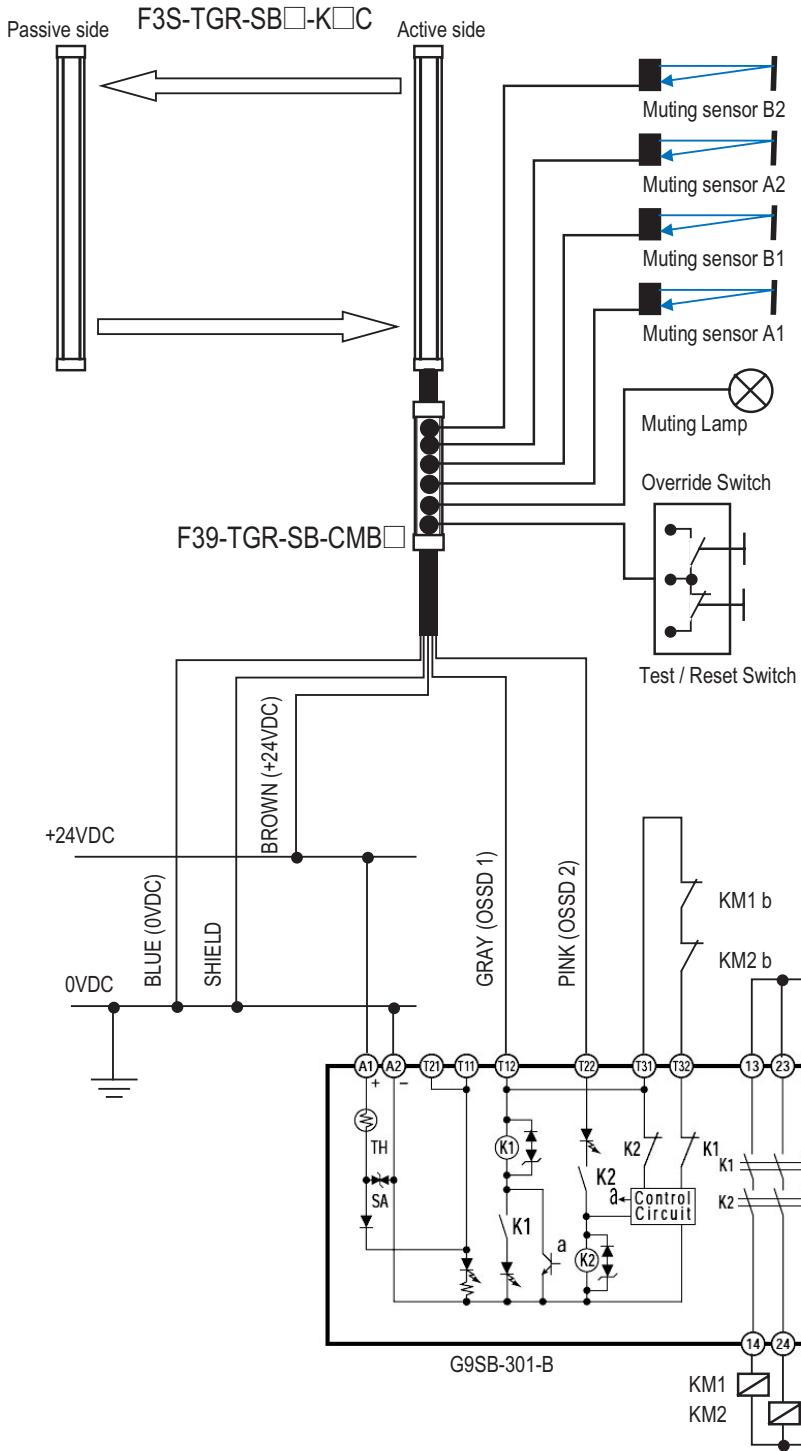
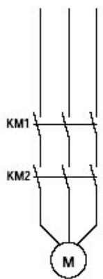
flowchart
graph TD
    A["Passive side"] --> B["F3S-TGR-SB□-K□C"]
    B --> C["Active side"]
    C --> D["Muting sensor B2"]
    C --> E["Muting sensor A2"]
    C --> F["Muting sensor B1"]
    C --> G["Muting sensor A1"]
    D --> H["Muting Lamp"]
    E --> I["Override Switch"]
    F --> J["Test / Reset Switch"]
    K["F39-TGR-SB-CMB"] --> L["BROWN (+24VDC)"]
    L --> M["BLEUE (0VDC)"]
    L --> N["SHIELD"]
    O["+24VDC"] --> P["BLUE"]
    P --> Q["SHIELD"]
    R["0VDC"] --> S["Ground"]
    T["GRAY (OSSD 1)"] --> U["PINK (OSSD 2)"]
    V["G9SB-301-B"] --> W["K1 a K2 a"]
    X["A1 A2 T21 T11 T12 T12 T13 T13 T13"] --> Y["Control Circuit"]
    Z["TH SA"] --> AA["Control Circuit"]
    AB["K1"] --> AC["Control Circuit"]
    AD["K2"] --> AE["Control Circuit"]
    AF["K1 b KM2"] --> AG["Control Circuit"]
    AH["K1"] --> AI["Control Circuit"]
    AJ["K2"] --> AK["Control Circuit"]
    AL["K1"] --> AM["Control Circuit"]
    AN["K2"] --> AO["Control Circuit"]
DIP switch Status of F3S-TGR-SB□-K□C
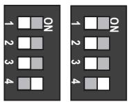
Manual Reset Mode:
Every DIP SW has to be OFF status
Factory setting:
Auto Reset Mode (Sw No 4 is ON)
F39-TGR-SB-CMB□ Plug reference
Muting Sensor (B2/A2/B1/A1)
Muting Lamp
Test and Override inputs
ALL DIMENSIONS SHOWN ARE IN MILLIMETERS.
To convert millimeters into inches, multiply by 0.03937. To convert grams into ounces, multiply by 0.03527.
- Safety sensor for Palletisers
- F3S-TGR-SB□C series
- Features
- For Palletiser
- Active - Passive system and Plug and play
- Different types available
- Muting functions are integrated
- Decentralized Muting connection Box
- Multiple mute connections are possible
- Muting Sensors Recommendation
- SOLUTION 1: Object Gaps
- SOLUTION 2: Misalignment of pallets
- Safety Multi beam Sensors
- Muting Connecting Box (Order Separately)
- Accessories (Order Separately)
- Dimensions
- F39-TGR-SB-CMB1
- Connector Plug Assemblies, Screw-on Type
- F3S-TGR-SB□-K□C
- Connection example
- F3S-TGR-SB-CMB□
- Manual Reset Mode (by Safety barrier)
Marque : OMRON
Modèle : F3S-TGR-SB
Catégorie : Capteur de sécurité