
F3S-TGR-N R - Capteur de sécurité OMRON - Notice d'utilisation et mode d'emploi gratuit
Retrouvez gratuitement la notice de l'appareil F3S-TGR-N R OMRON au format PDF.


| Type de produit | Capteur de sécurité magnétique sans contact |
| Marque | Omron |
| Modèle | F3S-TGR-N R (série F3S-TGR-N) |
| Variantes disponibles | Elongated (NLPR), Small (NSMR), Miniature (NMPR) |
| Matière du boîtier | Polycarbonate noir (NLPR, NSMR), Polyester noir (NMPR), Acier inoxydable (NSMR option) |
| Distance de fonctionnement (OFF→ON) | 10 mm (NLPR), 12 mm (NSMR, NMPR) |
| Distance de fonctionnement (ON→OFF) | 22 mm (NLPR), 20 mm (NSMR, NMPR) |
| Vitesse d'approche de l'actionneur | 4 mm/s min, 1000 mm/s max |
| Fréquence de commutation max. | 1 Hz |
| Température de fonctionnement | -25 °C à +80 °C (NLPR, NMPR), -25 °C à +105 °C (NSMR) |
| Indice de protection | IP67 (version câble ou connecteur M12) |
| Configuration des contacts | 2NC ou 2NC+1NO selon variante |
| Tension nominale des contacts | 250 VAC / 24 VDC |
| Courant de commutation nominal | 1 A (250 VAC) pour NC, 0,2 A (24 VDC) pour NO |
| Résistance de contact initiale | 50 mΩ max |
| Temps de relâchement des contacts | 2 ms max |
| Catégorie de sécurité (EN 954-1) | Jusqu'à catégorie 4 avec relais de sécurité approprié |
| Durée de vie mécanique | 10 000 000 cycles |
| Durée de vie électrique | 1 000 000 cycles (24 VDC / 100 mA avec facteur de sécurité 2) |
| Raccordement | Câble pré-câblé (2, 5, 10 m) ou connecteur M12 8 broches |
| Entretien et nettoyage | Nettoyer avec un chiffon doux ; éviter solvants (alcool, thinner, etc.) |
| Accessoires recommandés | Relais de sécurité G9SA, G9SB, G9SX ; câbles de connexion F39-TGR ; actionneur magnétique |
| Normes certifiées | EN 954-1, EN 60204-1, EN/IEC 60947-5-3, UL 508, CSA C22.2 |
| Garantie | 1 an (estimation) |
FOIRE AUX QUESTIONS - F3S-TGR-N R OMRON
Questions des utilisateurs sur F3S-TGR-N R OMRON
0 question sur cet appareil. Repondez a celles que vous connaissez ou posez la votre.
Poser une nouvelle question sur cet appareil
Téléchargez la notice de votre Capteur de sécurité au format PDF gratuitement ! Retrouvez votre notice F3S-TGR-N R - OMRON et reprennez votre appareil électronique en main. Sur cette page sont publiés tous les documents nécessaires à l'utilisation de votre appareil F3S-TGR-N R de la marque OMRON.
MODE D'EMPLOI F3S-TGR-N R OMRON
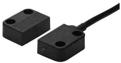
Compact Magnetic Non-contact Safety Switches
F3S-TGR-N□R
Magnetic Non-contact switches are designed to interlock hinge, sliding or removal guard doors.
- Contact-free detection of the closing/ opening of a door
- Non-contact = no abrasion = no particles
- Excellent coverage of mechanical tolerances
- Can operate behind stainless steel fittings
- Screw-hole covers support hygienic design (NMPR)
- Conforms to safety categories up to 4 acc. EN 954-1 and PDF-M acc. EN60947-5-3
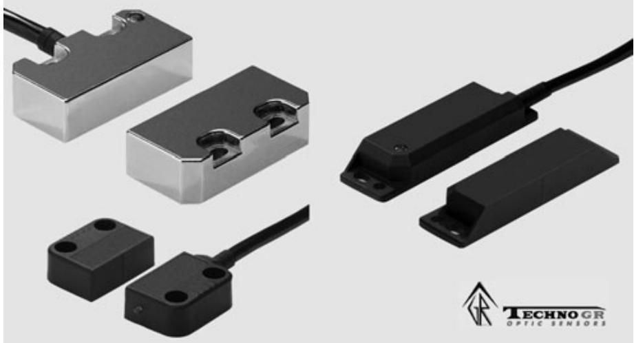
Model Number Structure
F3S-TGR-N□R-□-□12 3 4
- Type
L: Elongated Sensor
S: Small Sensor
M: Miniature Sensor
- Housing Material
P: Plastic Housing
M: Stainless Steel Housing
3: Contact configuration
20: 2 Normally Closed Contacts (NC)
21: 2 Normally Closed Contacts (NC) + 1 Normally Open Contact (NO)
4: Cable Length/connection for NLPR and NSMR
02: 2m Cable
05: 5m Cable
10: 10m Cable
M1J8: M12 male connector, 8pin
4: Cable Length/connection for NMPR
02: 2m Cable, cable exit to the left
05: 5m Cable, cable exit to the left
10: 10m Cable, cable exit to the left
M1J8: M12 male connector, 8-pin, cable exit to the left
Ordering Information
| Elongated Sensors | Type | Cable Connection | Contact Configuration |
| F3S-TGR-NLPR-20-02 | 2 m pre-wired | 2NC | |
| F3S-TGR-NLPR-20-05 * | 5 m pre-wired | 2NC | |
| F3S-TGR-NLPR-20-10 | 10 pre-wired | 2NC | |
| F3S-TGR-NLPR-20-M1J8 | M12, 8-pin | 2NC | |
| F3S-TGR-NLPR-21-02 | 2 m pre-wired | 2NC/1NO | |
| F3S-TGR-NLPR-21-05 * | 5 m pre-wired | 2NC/1NO | |
| F3S-TGR-NLPR-21-10 | 10 pre-wired | 2NC/1NO | |
| F3S-TGR-NLPR-21-M1J8 | M12, 8-pin | 2NC/1NO |
- . Preferred stock items.
| Small Sensor | Type | Cable Connection | Contact Configuration |
| F3S-TGR-NSMR-20-02 | 2 m pre-wired | 2NC | |
| F3S-TGR-NSMR-20-05 * | 5 m pre-wired | 2NC | |
| F3S-TGR-NSMR-20-10 | 10 pre-wired | 2NC | |
| F3S-TGR-NSMR-20-M1J8 | M12, 8-pin | 2NC | |
| F3S-TGR-NSMR-21-02 | 2 m pre-wired | 2NC/1NO | |
| F3S-TGR-NSMR-21-05 * | 5 m pre-wired | 2NC/1NO | |
| F3S-TGR-NSMR-21-10 | 10 pre-wired | 2NC/1NO | |
| F3S-TGR-NSMR-21-M1J8 | M12, 8-pin | 2NC/1NO |
- . Preferred stock items.
| Miniature Sensor | Type | Cable Connection | Contact Configuration |
| F3S-TGR-NMPR-20-02 | 2m pre-wired | 2NC | |
| F3S-TGR-NMPR-20-05 * | 5m pre-wired | 2NC | |
| F3S-TGR-NMPR-20-10 | 10m pre-wired | 2NC | |
| F3S-TGR-NMPR-20-M1J8 | M12, 8pin | 2NC | |
| F3S-TGR-NMPR-21-02 | 2m pre-wired | 2NC/1NO | |
| F3S-TGR-NMPR-21-05 * | 5m pre-wired | 2NC/1NO | |
| F3S-TGR-NMPR-21-10 | 10m pre-wired | 2NC/1NO | |
| F3S-TGR-NMPR-21-M1J8 | M12, 8pin | 2NC/1NO |
- . Optional cable exit to the right is available for F3S-TGR-NMPR - types. Please contact your Omron distributor
Accessories
| Safety relay units | G9SA | G9SA-301 G9SA-501 G9SA-321-T075 G9SA-321-T15 G9SA-321-T30 |
| G9SB | G9SB-2002-C G9SB-2002-A G9SB-200-B G9SB-200-D G9SB-3012-A G9SB-301-B G9SB-3012-C G9SB-301-D | |
| G9SX | G9SX-BC202-R_ | |
| G9SX-AD322-T15-R_ G9SX-AD322-T150-R_ G9SX-ADA222-T15-R_ G9SX-ADA222-T150-R_ | ||
| Programmable Controllers | Standalone controller 16 inputs | NE1A-SCPU01L |
| Standalone controller 40 inputs | NE1A-SCPU02L | |
| Safety Network controller 16 inputs | NE1A-SCPU01-V1 | |
| Safety Network controller 40 inputs | NE1A-SCPU02 | |
| Safety input terminal | DST1-ID12SL-1 | |
| Safety mixed terminal | DST1-MD16SL-1 | |
| Safety mixed terminal (relay out) | DST1-MRD08SL-1 | |
| Cables 8-pin | 2 m | F39-TGR-CVL-B-2-R |
| 5 m | F39-TGR-CVL-B-5-R | |
| 10 m | F39-TGR-CVL-B-10-R | |
| T-Connector Connection cable | for M12 connector - types | F39-TGR-NT |
| 2m M12-8pin, 2m | F39-TGR-CVL-N-2 | |
| 5m M12-8pin, 5m | F39-TGR-CVL-N-5 | |
| 10m M12-8pin, 10m | F39-TGR-CVL-N-10 |
Mechanical Data
| Elongated Sensor | Small Sensor | Miniature Sensor | ||
| Operating distance | OFF → ON (Sao) | 10 mm Close | 12 mm Close | |
| ON → OFF (Sar) | 22 mm Open | 20 mm Open | ||
| Actuator approach speed | Min. | 4mm/s | ||
| Max. | 1000mm/s | |||
| Switching frequency | Max. | 1Hz | ||
| Operating temperature | -25°C...+80°C | -25°C...+105°C | -25°C ... +80°C | |
| Enclosure protection | Flying lead M12 connector | IP 67 | ||
| Material | Black Polycarbonate | Stainless steel 316 | Black Polyester | |
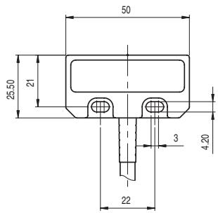
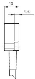
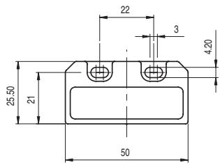
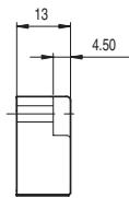
| Mounting bolts | 2 x M4 recommended | |||
| Tightening torque | Max. | 1 Nm | 0,8 Nm | |
| Mounting position | any | |||
| Mechanical life expectancy | 10.000.000 cycles | |||
| Electrical life expectancy | 1.000.000 cycles | |||
| De-rating Safety factor 2 | 2.000.000 cycles @ 24VDC/100mA | |||
| Cable diameter | 6 mm PVC | |||
Electrical Data
| Elongated Sensor | Small Sensor | Miniature Sensor | ||
| Contact release time | Max. | 2ms | ||
| Initial contact resistance | Max. | 50mΩ | ||
| Switching current | Min. | 1mA @ 10VDC | 10mA @ 10VDC | |
| Rated loads | NC contacts | 1A @ 250VAC | 0,5A @ 250VAC | |
| NO contacts | 0,2A @ 24VDC | 0,2A @ 24VDC | ||
| Insulation resistance | 100MΩ | |||
| Rated insulation voltage | 500VAC | 250VAC | ||
Approved Standards
EN standards certified by TUV Rheinland
EN 954-1
EN 60204-1
EN/IEC 60947-5-3
- UL 508, CSA C22.2
BS 5304
EN 1088-1 conformance
Connection diagram
Cable version
Pin No.
Signal name
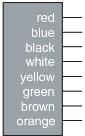
NC Channel 1
NC Channel 1
NC Channel 2
NC Channel 2
NO Channel
NO Channel
M12-Connector version
Pin No. Signal name
Wire color (F39-TGR-SB4-CVLB)



— Brown
Green
Blue
White
Yellow
Pink
Grey
Red
Note: If the auxiliary circuit is not fitted or not used then cut and discard the Yellow and Green Conductors.
Operating characteristics
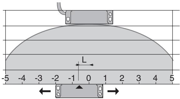
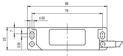
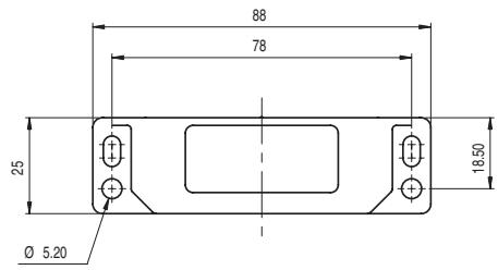
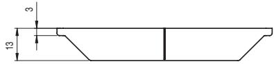
5 mm misalignment tolerance after setting
Elongated Sensor (Sensor/Actuator)
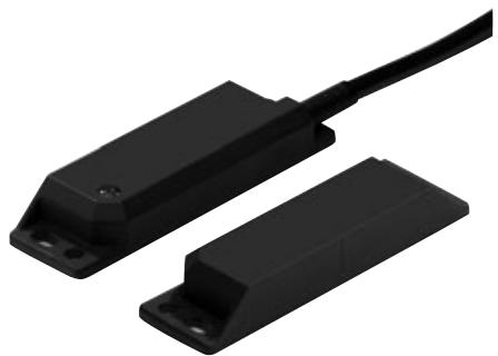
F3S-TGR-NLPR

Small Sensor (Sensor/Actuator)
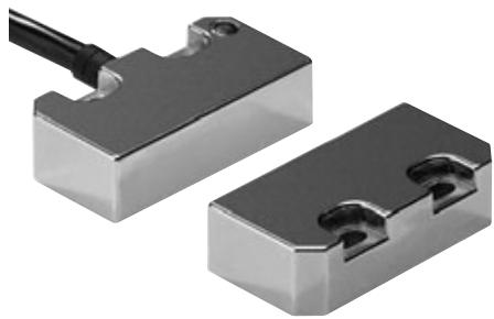
F3S-TGR-NSMR
Miniature Sensor (Sensor/Actuator)
F3S-TGR-NMPR
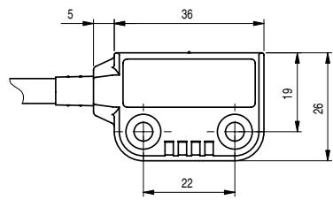
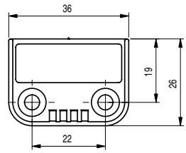
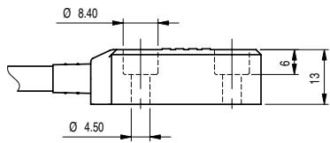
Wiring examples (Single head connection up to category 4 acc. EN954-1)
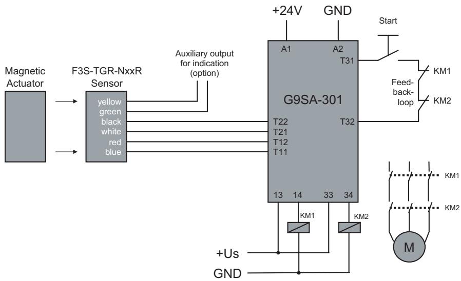
G9SA
Single Sensor Application with G9SA-301
(up to Safety Category 4 acc. EN954-1)
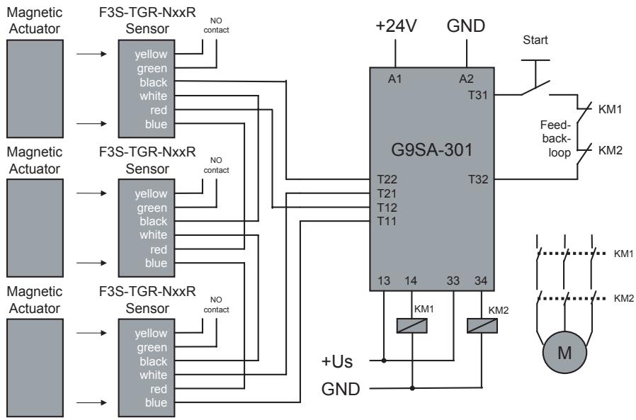
Series connection Application, up to 6 Sensors with G9SA-301
(up to Safety Category 3 acc. EN954-1)
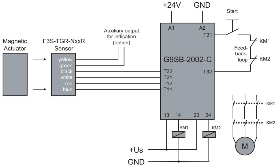
G9SB Single Sensor Application with G9SB-2002-C (up to Safety Category 4 acc. EN954-1)
Series connection Application, up to 6 Sensors with G9SB-2002-C (up to safety Category 3 acc. EN954-1)

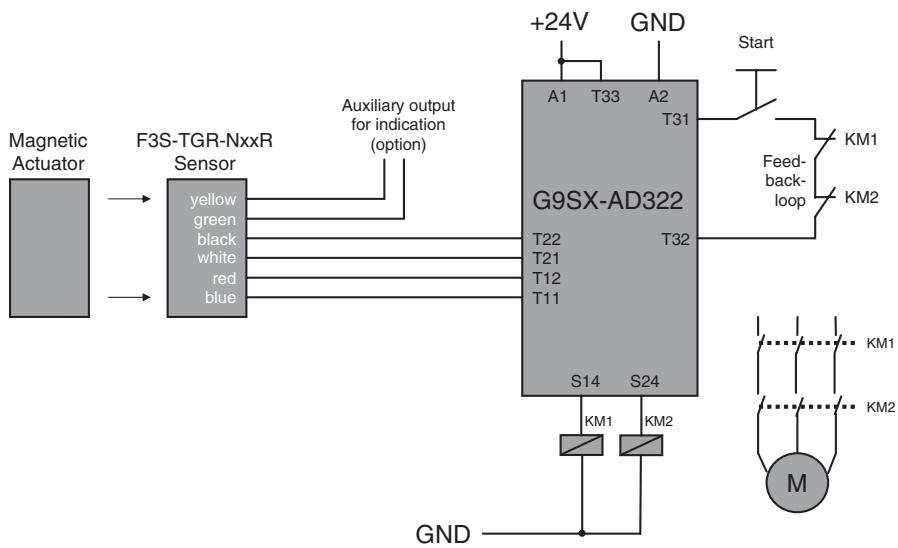
G9SX
Single Sensor Application with G9SX-AD322-T15
(up to Safety Category 4 acc. EN954-1)
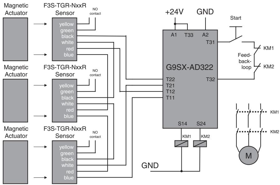
Series connection Application, up to 6 Sensors with G9SX-AD322-T15
(up to Safety Category 3 acc. EN954-1)
DeviceNet Safety NE1A and DST1-I/O-Terminals
Single Sensor Application with NE1A and DST1-Safety-IO
(up to safety Category 4 acc. EN954-1)
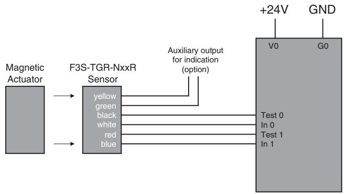
NE1A...
DST1-ID...
DST1-MD..
DST1-MRD..
Series connection Application, up to 6 Sensors with NE1A or DST1-Safety-IO
(up to Safety Category 3 acc. EN954-1)
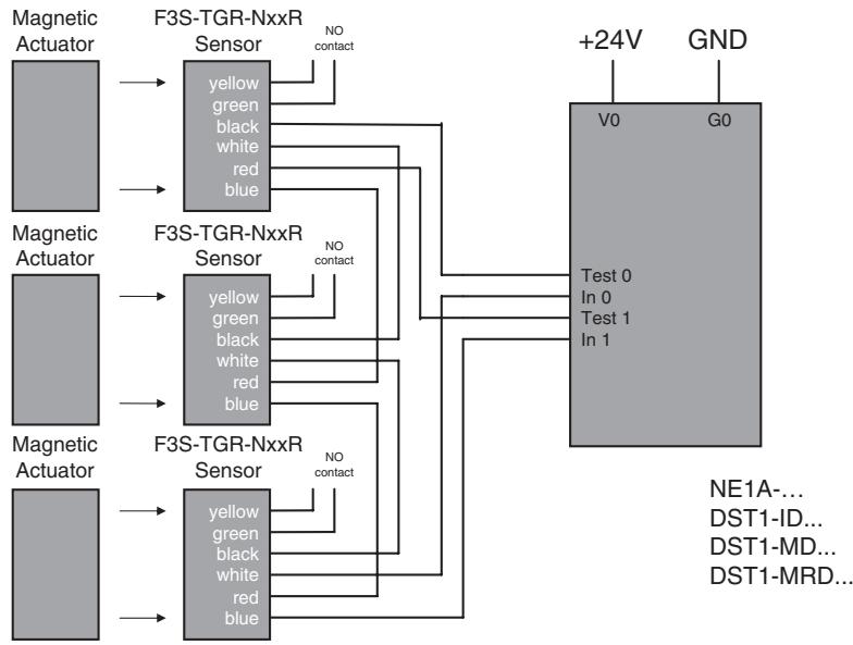
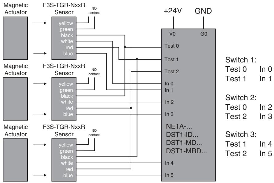
Application with multiple Sensors with NE1A or DST1-Safety-IO
(up to Safety Category 4 acc. EN954-1)
WARNING
Be sure to turn OFF the power before performing wiring. Do not touch charge parts (e.g., terminals) while power is ON. Doing so may result in electric shock.

Do not allow the actuator to come close to the switch with the door open. Doing so may cause machinery to start operating and may result in injury.

Keep actuators (magnets) away from magnetically sensitive equipment like PC harddisks, floppy disks etc. The magnetic field of the magnet will damage existing data.

CAUTION
Use guard stops in the way shown below to ensure that the switch and actuator do not make contact when the guard door is closed.

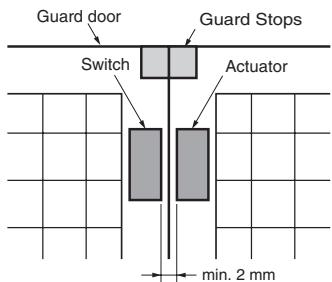
min. 5 mm (Standard Sensor) max. 4 mm (Elongated Sensor)
Application Precautions
- Do not use the product in locations subject to explosive or flammable gases.
- Do not use load currents exceeding the rated value.
- Be sure to wire each conductor correctly.
- Be sure to confirm correct operation after completing mounting and adjustment.
- Do not drop or attempt to disassemble the product.
- Be sure to use the correct combination of switch and actuator.
- Use a power supply of the specified voltage. Do not use power supplies with large ripples or power supplies that intermittently generate incorrect voltages.
- Capacitors are consumable and require regular maintenance and inspection.
Precautions for Safe Use
Mounting Direction of Switch and Actuator
The Sensor will not operate properly if the switch and actuator come towards each other diagonally. The Sensor will, however, operate properly if the switch and actuator come towards each other head-on, horizontally or vertically (as long as the faces have the same orientation).
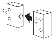
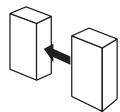
CORRECT
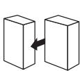
CORRECT
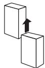
CORRECT

INCORRECT
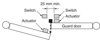
Mutual Interference
If the switch and actuator are mounted in parallel, be sure to separate them by at least 25mm , as shown below.
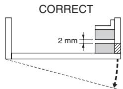
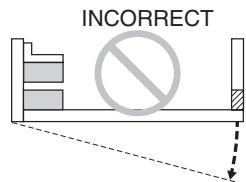
Using for Hinged Doors
On hinged doors, install the Sensor at an opening edge as shown below.
Solvents
Ensure that solvents, such as alcohol, thinner, trichloroethane, or gasoline do not adhere to the product. Solvents may cause markings to fade and components to deteriorate.
Installation Location
Do not install the product in the following locations. Doing so may result in product failure or malfunction.
- Locations subject to direct sunlight
- Locations subject to humidity levels outside the range 35% to 85% or subject to condensation due to extreme temperature changes
- Locations subject to corrosive or flammable gases
- Locations subject to shocks or vibration in excess of the product ratings
- Locations subject to dust (including iron dust) or salts
Take appropriate and sufficient countermeasures when using the product in the following locations.
- Locations subject to static electricity or other forms of noise
- Locations subject to possible exposure to radioactivity
- Locations subject to power supply lines
- It is advisable to mount the switches on non ferrous materials. The presence of ferrous material can effect switching sensitivity.
Wiring
Perform wiring using wire with the following dimensions.
Stranded wire: 2.5 mm^2
Solid wire: 4.0 mm^2
Tighten the terminal screws with the specified torque. Not doing so may result in malfunction or abnormal heat generation.
Terminal screw tightening torque: 1 Nm for NLPR and NSMR 0,8 Nm for NMPR
ALL DIMENSIONS SHOWN ARE IN MILLIMETERS.
To convert millimeters into inches, multiply by 0.03937. To convert grams into ounces, multiply by 0.03527.
- Compact Magnetic Non-contact Safety Switches
- F3S-TGR-N□R
- Magnetic Non-contact switches are designed to interlock hinge, sliding or removal guard doors.
- Model Number Structure
- F3S-TGR-N□R-□-□12 3 4
- Approved Standards
- Connection diagram
- Cable version
- M12-Connector version
- Operating characteristics
- Elongated Sensor (Sensor/Actuator)
- Small Sensor (Sensor/Actuator)
- Miniature Sensor (Sensor/Actuator)
- WARNING
- CAUTION
- Application Precautions
- Precautions for Safe Use
- Mutual Interference
- Using for Hinged Doors
- Solvents
- Installation Location
- Wiring
Marque : OMRON
Modèle : F3S-TGR-N R
Catégorie : Capteur de sécurité