
D4NS - Interrupteurs de fin de course OMRON - Notice d'utilisation et mode d'emploi gratuit
Retrouvez gratuitement la notice de l'appareil D4NS OMRON au format PDF.


| Type de produit | Interrupteur de fin de course de sécurité |
| Marque | OMRON |
| Modèle | D4NS |
| Catégorie | Interrupteur de sécurité pour portes |
| Tension nominale | 240 VAC (AC-15), 250 VDC (DC-13) |
| Courant nominal | 3 A (AC-15), 0.27 A (DC-13) |
| Degré de protection | IP67 (boîtier), IP00 (trou de clé) |
| Température d'utilisation | -30 °C à 70 °C |
| Durée de vie mécanique | 1 000 000 opérations min. |
| Durée de vie électrique | 500 000 opérations à 3 A/250 VAC |
| Force d'ouverture directe | 60 N min. |
| Course d'ouverture directe | 10 mm min. |
| Configuration des contacts | 1NC/1NO, 2NC, 2NC/1NO, 3NC, MBB |
| Matériau du boîtier | Résine |
| Poids | Environ 96 g (modèle D4NS-1CF) |
| Raccordement | Bornes à vis ou connecteur M12 |
| Normes | TÜV, UL, CSA, CCC |
| Clé de sécurité | Vendue séparément (D4DS-K1 à K5) |
FOIRE AUX QUESTIONS - D4NS OMRON
Questions des utilisateurs sur D4NS OMRON
0 question sur cet appareil. Repondez a celles que vous connaissez ou posez la votre.
Poser une nouvelle question sur cet appareil
Téléchargez la notice de votre Interrupteurs de fin de course au format PDF gratuitement ! Retrouvez votre notice D4NS - OMRON et reprennez votre appareil électronique en main. Sur cette page sont publiés tous les documents nécessaires à l'utilisation de votre appareil D4NS de la marque OMRON.
MODE D'EMPLOI D4NS OMRON
Safety-door Switch
D4NS
Multi-contact, Labor-saving, Environment-friendly, Next-generation Safety-door Switch
- Lineup includes three contact models with 2NC/1NC and 3NC contact forms in addition to the previous contact forms 1NC/1NO, and 2NC.
- M12-connector models are available, saving on labor and simplifying replacement.
- Standardized gold-clad contacts provide high contact reliability.
Applicable to both standard loads and micro loads. - Free of lead, cadmium, and hexavalent chrome, reducing the burden on the environment.
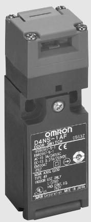
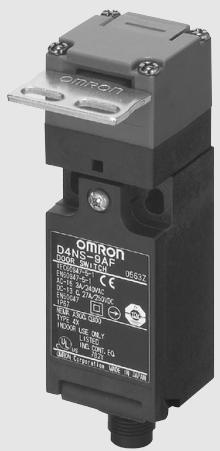
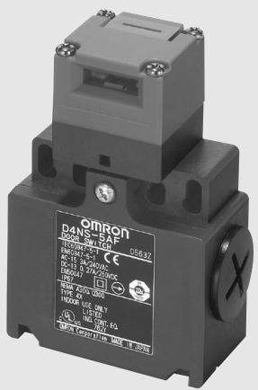


Model Number Structure
Model Number Legend
Switch

123
1. Conduit/Connector size
1: Pg13.5 (1-conduit)
2: G1/2 (1-conduit)
3: 1/2-14NPT (1-conduit)
4: M20 (1-conduit)
5: Pg13.5 (2-conduit)
6: G1/2 (2-conduit)
7: 1/2-14NPT compatible (2-conduit model with M20 conduit size includes an M20-to-1/2-14NPT conversion adapter)
8: M20 (2-conduit)
9: M12 connector (1-conduit)
2. Built-in Switch
A: 1NC/1NO (slow-action)
B: 2NC (slow-action)
C: 2NC/1NO (slow-action)
D: 3NC (slow-action)
E: 1NC/1NO (MBB contact)
F: 2NC/1NO (MBB contact)
3. Head Mounting Direction
F: Four mounting directions possible (Front-side mounting at shipping)
Note: An order for the head part or the switch part alone cannot be accepted.
The Operation Key is sold separately.
Operation Key

1
1. Operation Key Type
1: Horizontal mounting
2: Vertical mounting
3: Adjustable mounting (Horizontal)
5: Adjustable mounting (Horizontal/ Vertical)
Switches (Operation Keys are sold separately.)
Models with approved direct opening contacts.
List of Models
| Type | Contact configuration | Conduit opening/Connector | Model | |
| 1-conduit | Slow-action | 1NC/1NO | Pg13.5 | D4NS-1AF (note 3) |
| G1/2 | D4NS-2AF | |||
| 1/2-14NPT | D4NS-3AF | |||
| M20 | D4NS-4AF (note 3) | |||
| 2NC | Pg13.5 | D4NS-1BF (note 3) | ||
| G1/2 | D4NS-2BF | |||
| 1/2-14NPT | D4NS-3BF | |||
| M20 | D4NS-4BF (note 3) | |||
| 2NC/1NO | Pg13.5 | D4NS-1CF (note 3) | ||
| G1/2 | D4NS-2CF | |||
| 1/2-14NPT | D4NS-3CF | |||
| M20 | D4NS-4CF (note 3) | |||
| 3NC | Pg13.5 | D4NS-1DF | ||
| G1/2 | D4NS-2DF | |||
| 1/2-14NPT | D4NS-3DF | |||
| M20 | D4NS-4DF (note 3) | |||
| Slow-action MBB contact | 1NC/1NO | Pg13.5 | D4NS-1EF | |
| G1/2 | D4NS-2EF | |||
| 1/2-14NPT | D4NS-3EF | |||
| M20 | D4NS-4EF (note 3) | |||
| 2NC/1NO | Pg13.5 | D4NS-1FF | ||
| G1/2 | D4NS-2FF | |||
| 1/2-14NPT | D4NS-3FF | |||
| M20 | D4NS-4FF (note 3) | |||
| 2-conduit | Slow-action | 1NC/1NO | Pg13.5 | D4NS-5AF |
| G1/2 | D4NS-6AF | |||
| M20, includes M20-to-1/2-14NPT conversion adapter | D4NS-7AF | |||
| M20 | D4NS-8AF | |||
| 2NC | Pg13.5 | D4NS-5BF (note 3) | ||
| G1/2 | D4NS-6BF | |||
| M20, includes M20-to-1/2-14NPT conversion adapter | D4NS-7BF | |||
| M20 | D4NS-8BF (note 3) | |||
| 2NC/1NO | Pg13.5 | D4NS-5CF | ||
| G1/2 | D4NS-6CF | |||
| M20, includes M20-to-1/2-14NPT conversion adapter | D4NS-7CF | |||
| M20 | D4NS-8CF (note 3) | |||
| 3NC | Pg13.5 | D4NS-5DF | ||
| G1/2 | D4NS-6DF | |||
| M20, includes M20-to-1/2-14NPT conversion adapter | D4NS-7DF | |||
| M20 | D4NS-8DF | |||
| Slow-action MBB contact | 1NC/1NO | Pg13.5 | D4NS-5EF | |
| G1/2 | D4NS-6EF | |||
| M20, includes M20-to-1/2-14NPT conversion adapter | D4NS-7EF | |||
| M20 | D4NS-8EF | |||
| 2NC/1NO | Pg13.5 | D4NS-5FF | ||
| G1/2 | D4NS-6FF | |||
| M20, includes M20-to-1/2-14NPT conversion adapter | D4NS-7FF | |||
| M20 | D4NS-8FF | |||
| 1-conduit, with connec- tor | Slow-action | 1NC/1NO | M12 connector | D4NS-9AF (note 3) |
| 2NC | D4NS-9BF (note 3) | |||
| Slow-action MBB con- tact | 1NC/1NO | D4NS-9EF (note 3) | ||
Note: 1. The recommended models for equipment and machinery being exported to Europe are those with an M20 or Pg13.5 conduit sizes, and for North America, the recommended models are those with a 1/2-14NPT conduit sizes.
2. Resin is used as the material for the D4NS housing and head. Use the metal D4BS Safety-door Switch for applications requiring greater mechanical strength.
3. Preferred stock item
Operation Keys
| Type | Model |
| Horizontal mounting | D4DS-K1 |
| Vertical mounting | D4DS-K2 |
| Adjustable mounting (Horizontal) | D4DS-K3 |
| Adjustable mounting (Horizontal/Vertical) | D4DS-K5 |
Specifications
Approved Standards
| Agency | Standard | File No. |
| TÜV Product Service | EN60947-5-1 (approved direct opening)GS-ET-15 | B0306 39656052 |
| UL (See note.) | UL508, CSA C22.2 No.14 | E76675 |
Note: Approval for CSA C22.2 No. 14 is authorized by the UL mark.
Standards and EC Directives
- Conforms to the following EC Directives:
Machinery Directive
Low Voltage Directive
EN50047
EN1088
CCC (China Compulsory Certification) Mark
| Agency | Standard | File No. |
| CQC | GB14048.5 | Under application |
Approved Standard Ratings
TÜV (EN60947-5-1)
| Item | Utilization category | AC-15 | DC-13 |
| Rated operating current (Ie) | 3 A | 0.27 A | |
| Rated operating voltage (Ue) | 240 V | 250 V | |
Note: Use a 10-A fuse type gI or gG that conforms to IEC269 as a short-circuit protection device. This fuse is not built into the Switch.
UL/CSA (UL508, CSA C22.2 No. 14)
A300
| Rated voltage | Carry current | Current | Volt-amperes | ||
| Make | Break | Make | Break | ||
| 120 VAC | 10 A | 60 A | 6 A | 7,200 VA | 720 VA |
| 240 VAC | 30 A | 3 A | |||
Characteristics
| Degree of protection (See note 3.) | IP67 (EN60947-5-1)(This applies for the Switch only. The degree of protection for the key hole is IP00.) | ||
| Durability(See note 4.) | Mechanical | 1,000,000 operations min. | |
| Electrical | 500,000 operations min. for a resistive load of 3 A at 250 VAC (See note 5.)300,000 operations min. for a resistive load of 10 A at 250 VAC | ||
| Operating speed | 0.05 to 0.5 m/s | ||
| Operating frequency | 30 operations/minute max. | ||
| Direct opening force (See note 6.) | 60 N min. | ||
| Direct opening travel (See note 6.) | 10 mm min. | ||
| Contact resistance | 25 mΩ max. | ||
| Minimum applicable load (See note 7.) | Resistive load of 1 mA at 5 VDC (N-level reference value) | ||
| Rated insulation voltage (U1) | 300 V | ||
| Protection against electric shock | Class II (double insulation) | ||
| Pollution degree (operating environment) | 3 (EN60947-5-1) | ||
| Impulse withstand voltage (EN60947-5-1) | Between terminals of the same polarity | 2.5 kV | |
| Between terminals of different polarities | 4 kV | ||
| Between other terminals and uncharged metallic parts | 6 kV | ||
| Insulation resistance | 100 MΩ min. | ||
| Contact gap | 2 x 2 mm min | ||
| Vibration resistance | Malfunction | 10 to 55 Hz, 0.75-mm single amplitude | |
| Shock resistance | Destruction | 1,000 m/s2min. | |
| Malfunction | 300 m/s2min. | ||
| Conditional short-circuit current | 100 A (EN60947-5-1) | ||
| Rated open thermal current (Ith) | 10 A (EN60947-5-1) | ||
| Ambient temperature | Operating: -30°C to 70°C with no icing | ||
| Ambient humidity | Operating: 95% max. | ||
| Weight | Approx. 96 g (D4NS-1CF) | ||
Note: 1. The above values are initial values.
2. Once a contact has been used to switch a standard load, it cannot be used for a load of a smaller capacity. Doing so may result in roughening of the contact surface and contact reliability may be lost.
3. The degree of protection is tested using the method specified by the standard (EN60947-5-1). Confirm that sealing properties are sufficient for the operating conditions and environment beforehand. Although the switch box is protected from dust or water penetration, do not use the D4NS in places where foreign material may penetrate through the key hole on the head, otherwise Switch damage or malfunctioning may occur.
4. The durability is for an ambient temperature of 5^ to 35^ and an ambient humidity of 40% to 70% . For more details, consult your OMRON representative.
5. If the ambient temperature is greater than 35^ , do not pass the 3-A, 250-VAC load through more than 2 circuits.
6. These figures are minimum requirements for safe operation.
7. This value will vary with the switching frequency, environment, and reliability level. Confirm that correct operation is possible with the actual load beforehand.
Structure
D4NS-□A□,D4NS-□B□,D4NS-□E□
D4NS-□C□, D4NS-□D□, D4NS-□F□
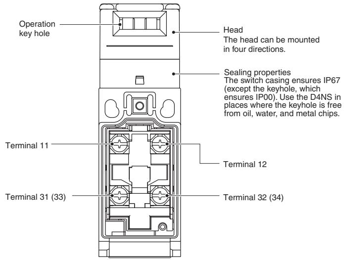
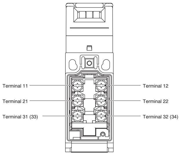
Note: The 2-conduit models have the same terminal arrangement.
Contact Form (Diagrams Show State with Key Inserted)
| Model | Contact | Contact form | Operating pattern | Remarks | ||
| D4NS-□A□ | 1NC/1NO | 11 12 33 34 | 11-12 33-34 | Stroke | ON | Only NC contacts 11-12 have an approved direct opening mechanism. The terminals 11-12 and 33-34 can be used as unlike poles. |
| D4NS-□B□ | 2NC | 11 12 31 32 | 11-12 31-32 | Stroke | ON | Only NC contacts 11-12 and 31-32 have an approved direct opening mechanism. The terminals 11-12 and 31-32 can be used as unlike poles. |
| D4NS-□C□ | 2NC/1NO | 11 12 21 22 33 34 | 11-12 21-22 33-34 | Stroke | ON | Only NC contacts 11-12 and 21-22 have an approved direct opening mechanism. The terminals 11-12, 21-22, and 33-34 can be used as unlike poles. |
| D4NS-□D□ | 3NC | 11 12 21 22 31 32 | 11-12 21-22 31-32 | Stroke | ON | Only NC contacts 11-12, 21-22, and 31-32 have an approved direct opening mechanism. The terminals 11-12, 21-22, and 31-32 can be used as unlike poles. |
| D4NS-□E□ | 1NC/1NO MBB | 11 12 33 34 | 11-12 33-34 | Stroke | ON | Only NC contacts 11-12 have an approved direct opening mechanism. The terminals 11-12 and 33-34 can be used as unlike poles. |
| D4NS-□F□ | 2NC/1NO MBB | 11 12 21 22 33 34 | 11-12 21-22 33-34 | Stroke | ON | Only NC contacts 11-12 and 21-22 have an approved direct opening mechanism. The terminals 11-12, 21-22 and 33-34 can be used as unlike poles. |
Note: MBB (Make Before Break) contacts have an overlapping structure, so that before the normally closed contact (NC) opens, the normally open contact (NO) closes.
Note: All units are in millimeters unless otherwise indicated.
Switches
1-conduit Models
| D4NS-1□F |
| D4NS-2□F |
| D4NS-3□F |
| D4NS-4□F |
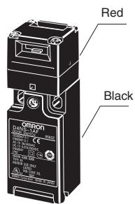
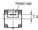
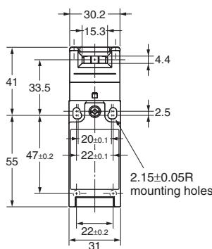
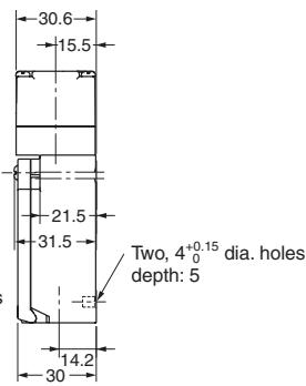
| Operating characteristics | D4NS-1□F D4NS-2□F D4NS-3□F D4NS-4□F |
| Key insertion force | 15 N max. |
| Key extraction force | 30 N max. |
| Pretravel (PT) | 6±3 mm |
| Total travel (TT) | (28 mm) |
| Direct opening force* | 60 N min. |
| Direct opening stroke* | 10 mm min. |
- Always maintain the above operating characteristics for safe use.
2-conduit Models
| D4NS-5□F |
| D4NS-6□F |
| D4NS-7□F |
| D4NS-8□F |
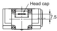
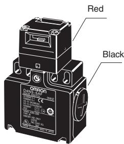
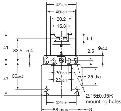
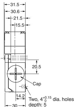
| Operating characteristics | D4NS-5□F D4NS-6□F D4NS-7□F D4NS-8□F |
| Key insertion force | 15 N max. |
| Key extraction force | 30 N max. |
| Pretravel (PT) | 6±3 mm |
| Total travel (TT) | (28 mm) |
| Direct opening force* | 60 N min. |
| Direct opening stroke* | 10 mm min. |
- Always maintain the above operating characteristics for safe use.
1-conduit Connector Models
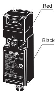
D4NS-9□F
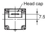
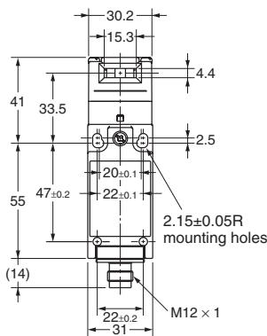
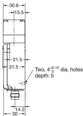
Note: Unless otherwise specified, a tolerance of ± 0.4mm applies to all dimensions.
| Operating characteristics | D4NS-9□F |
| Key insertion force | 15 N max. |
| Key extraction force | 30 N max. |
| Pretravel (PT) | 6±3 mm |
| Total travel (TT) | (28 mm) |
| Direct opening force* | 60 N min. |
| Direct opening stroke* | 10 mm min. |
- Always maintain the above operating characteristics for safe use.
Operation Keys
Note: Unless otherwise specified, a tolerance of ± 0.4mm applies to all dimensions.
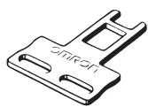
D4DS-K1
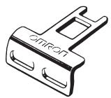
D4DS-K2
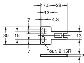
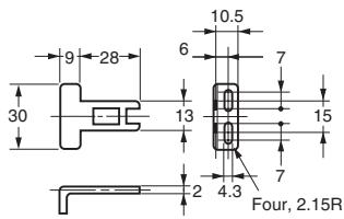
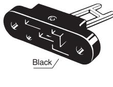
D4DS-K3
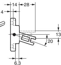
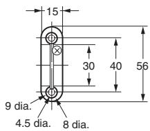
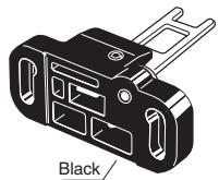
D4DS-K5
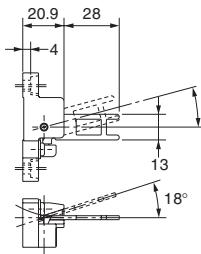
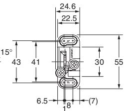
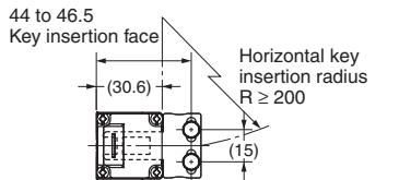
With Operation Key Inserted (Relationship between Insertion Radius and Insertion Hole)
Note: Unless otherwise specified, a tolerance of ± 0.4mm applies to all dimensions.
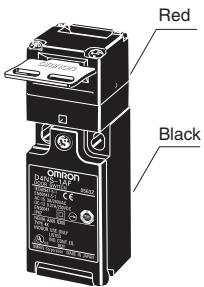
D4NS-1□F + D4DS-K1
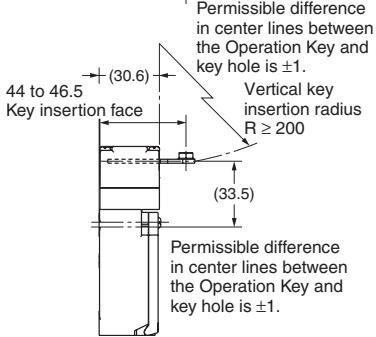
D4NS-1□F + D4DS-K2
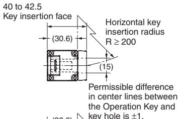
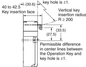
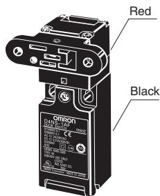
D4NS-1□F + D4DS-K3
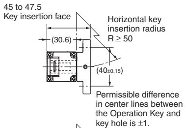
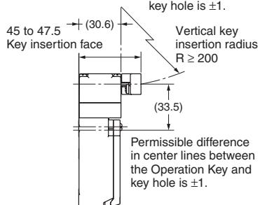
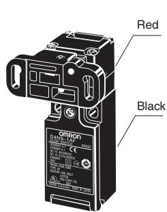
D4NS-1□F + D4DS-K5
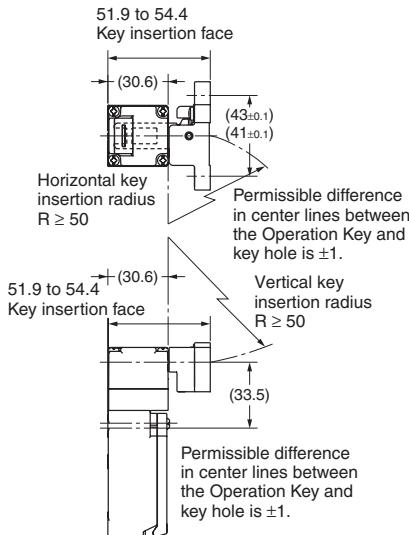
Refer to OMRON SAFETY COMPONENTS SERIES (Y106) for common precautions.
CAUTION
Do not dismount the operation key from the door intentionally and insert it to the switch with the door open. Machine may start operating and injury or death may be caused.
Do not use metal connector or conduit with this switch. The broken conduit hole may cause electrical shock hazard.
Precautions for Safe Use
- Be careful not to drop your D4NS, or the switch will not fully exhibit its ability.
- Do not disassemble or remodel your D4NS in any case, or the D4NS will not operate normally.
- Do not use the switch where explosive gas, ignitable gas, or any other harmful gasses may be present.
- Install operation key so that it will not hit the operator when the door is open. Injury may be caused.
- Do not use the switch in the oil and in the water. IP67(EN60947-5-1)
- Though the switch body is protected from the ingress of dust or water, avoid the ingress of foreign substance through the key hole on the head.
Otherwise, wear in short time or break may be caused
- Do not put the electric power when wiring.
- Be sure to install a cover after the wiring. Do not put the electric power when opening a cover.
- Connect the fuse to the switch in series to prevent it from short circuit damage.
The value of the breaking current of the fuse must be increased to cover the rated current by 150 to 200% . When using the switch with EN rating, use 10 A fuse, type gl or gG that complies with IEC 60269.
- Keep the electrical load below the rated value.
- On the switching of general loads (250VAC/3A), do not operate two circuits or more at the same time. Otherwise, insulation performance may be degraded.
- The durability of the switch is seriously affected by operating conditions.
Evaluate the switch under actual working conditions before permanent installation. - Please mention in machine manufacturer's Instruction. Manual that the user must not repair nor maintain the switch and must contact machine manufacturer for them.
- Do not use the switch as a stopper.
Be sure to install a stopper as shown in the following illustration to prevent the edge of the operation key from inadvertently hitting the switch directly.
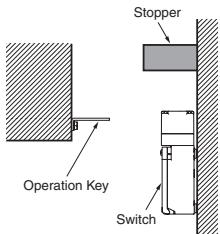
Precautions for Correct Use
1. Environment
- The switch is intended for indoor use only.
- Do not use your D4NS outdoor, or the switch will malfunction.
- Do not use your D4NS in the atmosphere of hazardous gases (H2S, SO2, NH3, HNO3, Cl2, etc.) or high temperature and humidity, or it will cause the imperfect closing of the contacts or the breakage thereof stemming from corrosion.
-
Do not use the switch under any of the conditions mentioned below.
-
Frequent temperature range.
- High humidity or dew condensation may be generated.
- Where the switch is subject to severe vibration.
- Where the metal dust, oil, or chemical is sprayed inside the door.
- Where thinner is applied.
2. Mounting method
- Mounting Screw Tightening Tor
Loose mounting may result in malfunction.
Fasten the screws to the specified torque.
| Terminal screw | 0.6 to 0.8 N·m |
| Cover clamping screw | 0.5 to 0.7 N·m |
| Head clamping screw | 0.5 to 0.6 N·m |
| Operation Key clamping screw (See item 4) | 2.4 to 2.8 N·m |
| Body clamping screw (See item 4) | 0.5 to 0.7 N·m |
| Conduit mounting connection (see item 10,11), M12 changing adaptor | 1.8 to 2.2 N·m |
| 1.4 to 1.8 N·m (1/2-14NPT) | |
| Cap screw | 1.3 to 1.7 N·m |
-
Switch, operation key
-
The switch and operation key will be fastened to specified torque in item 2 with M4 screws and washers.
- Secured more by the studs like below picture 4-0.05/-0.15 dia., 4.8 max. height at the lower two which are inserted from back side of switch.
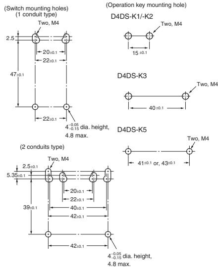
- Do not use the operation key other than dedicated OMRON's. Otherwise switch may be damaged.
- Be sure that the operation key can be inserted properly to key hole with a tolerance of ± 1 mm.
3. Head direction
The rotation of the switch head may be adjusted to any of the four directions by loosening the head clamping screws at the four corners of the head.
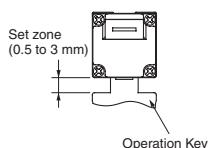
4. Securing of the door
If the operation key is pulled in the opening direction due to a force caused by vibration, by the door weight, or by a cushion attached to the door.
The closed door must be secured with a hook or by similar means.
5. Wiring
- When connect with insulation tubes and terminals, connect the terminals as shown in the following figure and wire without overriding to the case and the cover. Adequate conductor size is AWG 20 to 18 (0.5 to 0.75 ~mm^2 ).
Wire leads as shown in the following figure. Otherwise, the switch cover does not fit.
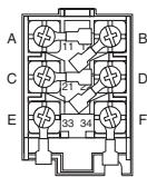
(1 conduit type)
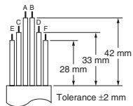
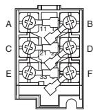
(2 conduits type)
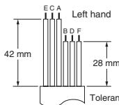
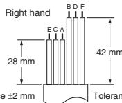
- Do not push the ring connector and the likes into the opening between the parts in order to prevent the case from being broken and deformed.
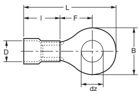
- Use terminals having the thickness of 0.5mm or less to avoid the contact between the terminal and the switch case inside.
The below listed the terminals have thickness of 0.5mm or less.
| Manufacture | Type | Wire size |
| J.S.T. | FV0.5-3.7 (F type) | AWG22 to 20 |
| V0.5-3.7 (straight type) |
J.S.T is a Japanese manufacturer.
t: dz dia.: D dia.: B: L: F: I:
0.5 mm
3.7 mm
2.9 mm
6.6 mm
19 mm
7.7 mm
8.0 mm
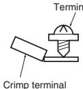
Correct
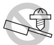
Incorrect
6. Contact arrangement
- The following show a safety contact and an auxiliary contact for 3 contacts and 2 contacts types.
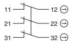
(Screw terminal type)
D4NS-□DF (3NC)
D4NS-□BF (2NC)
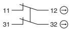
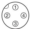
(Connector type)
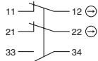
D4NS-□CF (2NC/1NO)
D4NS-FF (2NC/1NO (MBB))
D4NS-□AF (1NC/1NO)
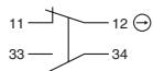
D4NS-FF (1NC/1NO (MBB))
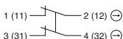
D4NS-9BF (2NC)
D4NS-9AF (1NC/1NO)
D4NS-9EF (1NC/1NO (MBB))
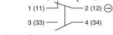
Suitable socket is Type XS2F (OMRON).
7. Socket tightening (connector type)
Do not use any tools, such as pliers, otherwise the socket connector may become damaged. Connect the socket connector to the connector threads of the D4NS. Then firmly turn the socket connector by hand so that the connector threaded portion will be completely covered by the socket connector so that space will be almost 0.
Make sure, however, that the socket connector is tightened securely, otherwise the rated degree of protection of the D4NS may not be maintained. Furthermore, the socket connector may be loosened by vibration.
8. Conduit opening
Use the connectors recommended in clause 9 and tighten the connector with specified torque in clause 2. An excessive torque will bring a case breakage.
Apply sealing tape between connector and conduit opening so that the enclosure will conform to IP67.
Use a cable with a suitable diameter for the connector.
For unused conduit opening, apply a conduit cap provided and tighten it to specified torque in clause 2.
9. Recommendation of connector
Use the connector with thread section of 9mm long or less. In the case of the connector with longer thread section, protruded part may interfere with the other parts inside the body. Use below listed connector to secure IP67.
| Size | Manufacture | Type | Adequate cable Diameter |
| G1/2 | LAPP | ST-PF1/2 5380-1002 | 6.0 to 12.0 mm |
| Ohm Denki | OA-W1609 | 7.0 to 9.0 mm | |
| OA-W1611 | 9.0 to 11.0 mm | ||
| Pg13.5 | LAPP | S-13.5 5301-5030 | 6.0 to 12.0 mm |
| M20 | LAPP | ST-M20 × 1.5 5311-1020 | 7.0 to 13.0 mm |
| 1/2-14NPT | LAPP | ST-NPT1/2 5301-6030 | 6.0 to 12.0 mm |
| HEYCO | 4.3 to 11.9 mm | ||
| M12 | LAPP | ST-M12 × 1.5 5301-1000 | 3.5 to 7.0 mm |
When use LAPP's products, use together with a seal packing which is sold separately (Type names, JPK-16, GP-13.5, GPM20. GPM12 is for M12 connector) and tighten with proper tightening torque.
LAPP is a German manufacturer.
Ohm Denki is a Japanese manufacturer.
HEYCO is an American manufacturer.
Before using the 2 conduit type 1/2-14NPT connector, attach the appended changing adapter to the switch, and wind the seal tape about the joint of the adapter and switch.
When use M12 conduit type, connect the above listed connector, after tightened the M12 changing adaptor to the switch.
The M12 changing adaptor is enclosed with the packing.
10. Storage
Do not keep the switch in dusty, humid place and any place where gas may be present for example H2S, SO2, NH3, HNO3, Cl2.
11. Others
- Do not impose excessive force on the key top while the operation key is inserted into the switch body or drop the switch with the operation key inserted to avoid the deformation of the key or the breakage of the switch body.
- Confirm that the seal rubber has no abnormality and then use it. If the seal rubber is displaced or floated, or if foreign matters adhere to the seal rubber, the seal rubber will lose its sealing capability.
- Do not use any screw other than correct one, or the sealing capability of the seal rubber will deteriorate.
- Please do a regular check in premeditation for this switch.
Following the release of the D4NS, production of the D4DS will be terminated.
Date of Production Termination
Production of the D4DS Series will be terminated in July 2006.
Date of Substitute Product Release
Sale of the D4NS Series commenced in July 2003.
Product Replacement
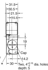
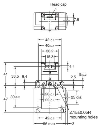
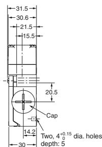
- Dimensions
The D4DS and D4NS have basically the same structure, and use the same mounting method, Operation Keys, mounting hole and Operation Key insertion positions. The multi-contact structure and the extra 4mm in length, however, are different.
- Terminal Numbers
For the 2-contact model, the terminals 21, 22, 23, and 24 on the D4DS are 31, 32, 33, and 34 on the D4NS.
- Recommended Terminals
If the recommended terminals are not used, the Switch may not be compatible. Make sure that the Switch is compatible with the terminals.
Comparison of the D4DS and Substitute Products
| Model | D4NS-□ |
| Switch color | Very similar |
| Dimensions | Very similar |
| Wiring/connection | Significantly different |
| Mounting method | Very similar |
| Ratings/performance | Very similar |
| Operating characteristics | Very similar |
| Operating method | Completely compatible |
Dimensions (Unit: mm)
List of Recommended Substitute Products
Switch
| D4DS product | Recommended substitute product |
| D4DS-15FS | D4NS-1AF |
| D4DS-25FS | D4NS-2AF |
| D4DS-35FS | D4NS-3AF |
| D4DS-55FS | D4NS-5AF |
| D4DS-65FS | D4NS-6AF |
| D4DS-1AFS | D4NS-1BF |
| D4DS-2AFS | D4NS-2BF |
| D4DS-3AFS | D4NS-3BF |
| D4DS-5AFS | D4NS-5BF |
| D4DS-6AFS | D4NS-6BF |
Operation Key
D4DS-K1
D4DS-K2
D4DS-K3
D4DS-K5
All of the above Operation Keys can be used with the D4NS.
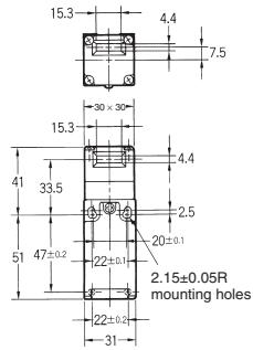
Discontinued Models (1-conduit D4DS)
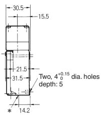
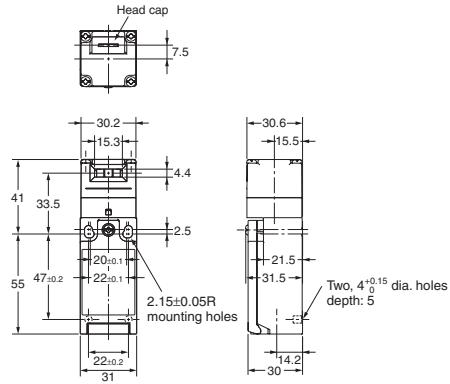
Replacement products (1-conduit D4NS)
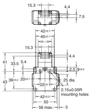
Discontinued Model (2-conduit D4DS)
Replacement products (2-conduit D4NS)

WARNING
This catalog is a guide to help customers select the proper safety product. Observe the following items when choosing products, select the right product for your device or equipment, and develop a safety-related system to fully utilize the product's functions.
Setting up a risk assessment system
The items listed in this catalog must be used properly in terms of product location as well as product performance and functionality. Part of the process of selecting and using these products should include the introduction and development of a risk assessment system early in the design development stage to help identify potential dangers in your equipment that will optimize safety product selection. A badly designed risk assessment system often results in poor choices when it comes to safety products.
- Related international standard: ISO 14121 "Principles of risk assessment."
Safety policy
When developing a safety system for the devices and equipment that use safety products, make every effort to understand and conform to the entire series of international and industrial standards available, such as the examples given below.
- Related international standards: ISO/DIS 12100 "Basic concepts, general principles for design" IEC 61508 "Functional safety of electrical/electronic/programmable electronic safety-related systems."
Role of safety products
Safety products have functions and mechanisms that ensure safety as defined by standards. These functions and mechanisms are designed to attain their full potential within safety-related systems. Make sure you fully understand all functions and mechanisms, and use that understanding to develop systems that will ensure optimal usage.
- Related international standard: ISO 14119 "Interlocking devices associated with guards- Principles for design and selection."
Installing safety products
Make sure that properly educated and trained engineers are selected to develop your safety-related system and to install safety products in devices and equipment.
- Related international standards: ISO/DIS 12100 "Basic Concepts, general principles for design." IEC 61508 "Functional safety of electrical/electronic/programmable electronic safety-related systems."
Observing laws and regulations
Safety products should conform to pertinent laws, regulations and standards, but make sure that they are used in accordance with the laws, regulations and standards of the country where the devices and equipment incorporating these products are distributed.
- Related international standard: IEC 60204 "Electrical equipment of machines."
Observing usage precautions
Carefully read the specifications and precautions listed in this catalog for your product as well as all items in the Operating Manual packed with the product to learn usage procedures that will optimize your choice. Any deviation from precautions will lead to unexpected device or equipment failure not anticipated by safety-related systems or fire originating from equipment failure.
Transferring devices and equipment
When transferring devices and equipment, be sure to keep one copy of the Operating Manual and pack another copy with the device or equipment so the person receiving it will have no problem operating it.
- Related international standards: ISO/DIS 12100 "Basic concepts, general principles for design" IEC 61508 "Functional safety of electrical/electronic/programmable electronic safety-related systems."
ALL DIMENSIONS SHOWN ARE IN MILLIMETERS.
To convert millimeters into inches, multiply by 0.03937. To convert grams into ounces, multiply by 0.03527.
- Safety-door Switch
- D4NS
- Multi-contact, Labor-saving, Environment-friendly, Next-generation Safety-door Switch
- Model Number Structure
- Model Number Legend
- Switch
- Conduit/Connector size
- Built-in Switch
- Head Mounting Direction
- Operation Key
- Operation Key Type
- Specifications
- Approved Standard Ratings
- Structure
- Switches
- 2-conduit Models
- 1-conduit Connector Models
- Operation Keys
- With Operation Key Inserted (Relationship between Insertion Radius and Insertion Hole)
- CAUTION
- Precautions for Safe Use
- Precautions for Correct Use
- Environment
- Mounting method
- Head direction
- Securing of the door
- Wiring
- Contact arrangement
- Socket tightening (connector type)
- Conduit opening
- Recommendation of connector
- Storage
- Others
- Product Replacement
- WARNING
- Setting up a risk assessment system
- Safety policy
- Role of safety products
- Installing safety products
- Observing laws and regulations
- Observing usage precautions
- Transferring devices and equipment
Marque : OMRON
Modèle : D4NS
Catégorie : Interrupteurs de fin de course