Delta 8000 BT - Automatisme domotique DELTA DORE - Notice d'utilisation et mode d'emploi gratuit
Retrouvez gratuitement la notice de l'appareil Delta 8000 BT DELTA DORE au format PDF.


| Type de produit | Unité technique pour système de gestion de chauffage/refroidissement |
| Marque | DELTA DORE |
| Modèle | Delta 8000 BT |
| Catégorie | Automatisme domotique |
| Dimensions | 250 x 95 x 43 mm |
| Alimentation | 230 V~/240 V~ +/-10%, 50/60 Hz |
| Consommation électrique | 2 à 15 VA (5,5 W max.) selon les éléments connectés |
| Nombre de sorties commandées | 8 sorties pour vannes/registres (contact sec, max. 1 A par sortie) |
| Sorties pour circulateur et générateur | 2 sorties contact sec (max. 2 A, 230 V~/240 V~) |
| Communication | Bus filaire (2 bus) et sans fil (via passerelle Delta 8000 RF) |
| Gestion des zones | Jusqu'à 8 zones avec actionneurs 2 fils, ou 4 zones avec actionneurs 3 fils |
| Types d'installation | Hydraulique (plancher/radiateur) et aéraulique (gainable) |
| Indice de protection | IP33 |
| Température de fonctionnement | 0 °C à +50 °C |
| Température de stockage | -10 °C à +70 °C |
| Classe d'isolation | Classe II |
| Type d'action | Type 1.C (micro-interruption) |
| Tension de tenue aux chocs | 2500 V |
| Fonction anti-seizure | Oui (démarrage automatique 1 à 10 minutes par semaine) |
| Conformité | CE |
| Référence constructeur | 2704571 Rev.03 |
| Entretien | Nettoyer avec un chiffon sec, déconnecter l'alimentation avant toute intervention |
| Sécurité | Installation par un professionnel qualifié, respecter les normes électriques en vigueur |
| Réparabilité | Faire appel à un professionnel qualifié pour toute réparation ou contacter le service après-vente DELTA DORE |
FOIRE AUX QUESTIONS - Delta 8000 BT DELTA DORE
Questions des utilisateurs sur Delta 8000 BT DELTA DORE
0 question sur cet appareil. Repondez a celles que vous connaissez ou posez la votre.
Poser une nouvelle question sur cet appareil
Téléchargez la notice de votre Automatisme domotique au format PDF gratuitement ! Retrouvez votre notice Delta 8000 BT - DELTA DORE et reprennez votre appareil électronique en main. Sur cette page sont publiés tous les documents nécessaires à l'utilisation de votre appareil Delta 8000 BT de la marque DELTA DORE.
MODE D'EMPLOI Delta 8000 BT DELTA DORE
Delta 8000 BT
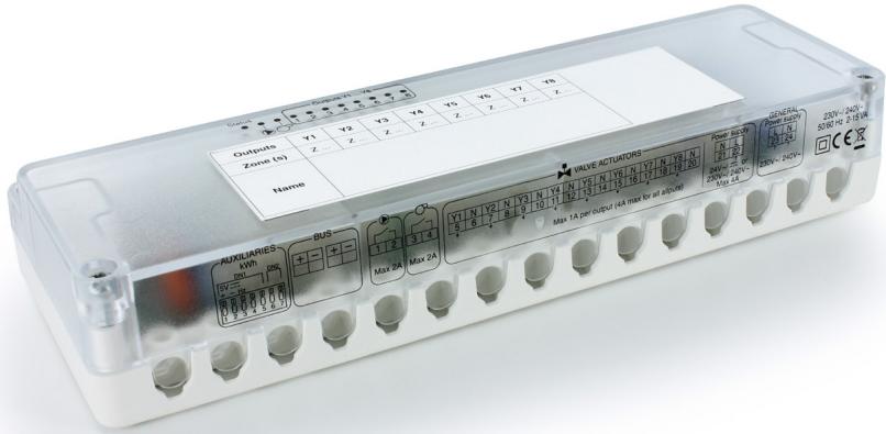
EN Technical unit for Delta 8000 system
Installation guide
Detailed online instructions
Access the detailed online instructions by scanning the QR code:
- Advanced configuration of the technical unit (TU),
- Installation of the peripheral devices (Bus and wireless RT/PRT),
- Advanced configuration of the peripheral devices (Bus and wireless RT/PRT),
• Operation with the Tydom application, - Access to the setup menus,
- Troubleshooting.

Contents
1/ System presentation......4
1.1 Presentation......4
1.2 Installation diagrams....5
2/ Mounting and Connection....7
2.1 Delta 8000 BT....7
2.2 Delta 8000 RF....10
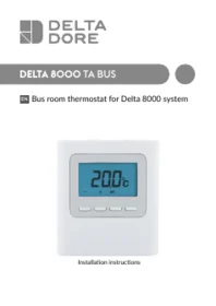
2.3 Delta 8000 TA RF and TA Bus....11
3/ Pairing of peripheral products with the Delta 8000 TU....13
3.1 Pairing a Delta 8000 TA RF gateway 13
3.2 Pairing a Delta 8000 TA RF 13
3.3 Pairing a Delta 8000 TA Bus....14
4/ Switch configuration....17
5/ Description of the LEDs of the BT Delta 8000....18
6/ Technical Specifications ....19
1/ System presentation
1.1 Presentation
Delta 8000 is a heating/cooling management system for hydraulic installations (under-floor or radiators) or for aeraulic installations (ductable).
This control system consists of several elements, which communicate either via a hard-wired connection (Bus), or wirelessly:
- Technical unit (Delta 8000 BT), the heart of the heating/cooling control system, which functions natively via a hard-wired connection (Bus)
- Delta 8000 room thermostat: simplified interface for mode and set point management. It is available in 2 versions: hard-wired (Delta 8000 Bus RT) or wireless(*) (Delta 8000 RF RT)
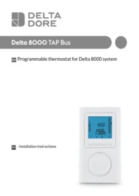
- Delta 8000 programmable room thermostat: interface for mode and set point programme and management.
It is available in 2 versions: hard-wired (Delta 8000 Bus PRT) or wireless(*) (Delta 8000 RF PRT)
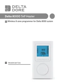
- Wireless room programmer(*) (Delta 8000 Master): takes care of weekly programming and the central control of the different zones
(*): requires the Delta 8000 RF wireless/Bus gateway, which thus enables the expansion of the system's compatibility to include window/door magnetic contacts, the outdoor temperature sensor, or even the smart home hub or bioclimatic manager.
Wireless and bus solutions can be used concomitantly on the same installation. A technical unit can manage up to 8 zones equipped with actuators with a 2-wire connection (electro-thermal head) or up to 4 zones equipped with actuators with a 3-wire connection (motorised head). It is possible to add a technical unit (configured as a slave) to double the capacity.
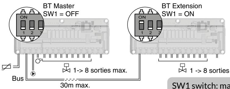
SW1 switch: master/slave configuration (see the "Technical unit configuration" section)
1.2 Installation diagrams
Delta 8000 can accommodate 2 types of installation : hydraulic (under-floor and/or radiator) or aeraulic (ductable) installation.
1.2.1 Example of a hydraulic application with Bus thermostats
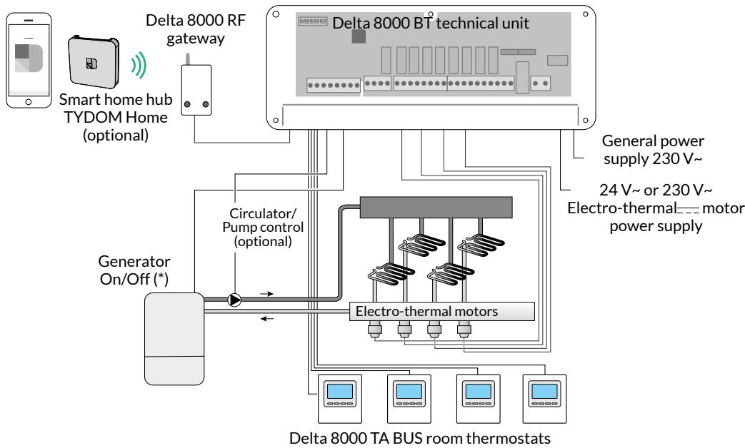
(*) The On/Off control cannot replace the generator's/boiler's short cycle protection. In the case whereby all parts are controlled, without exception, by the Delta 8000, it is recommended that you install a bypass.
1/ Presentation of the system
1.2.2 Example of an aeraulic application with wireless thermostats
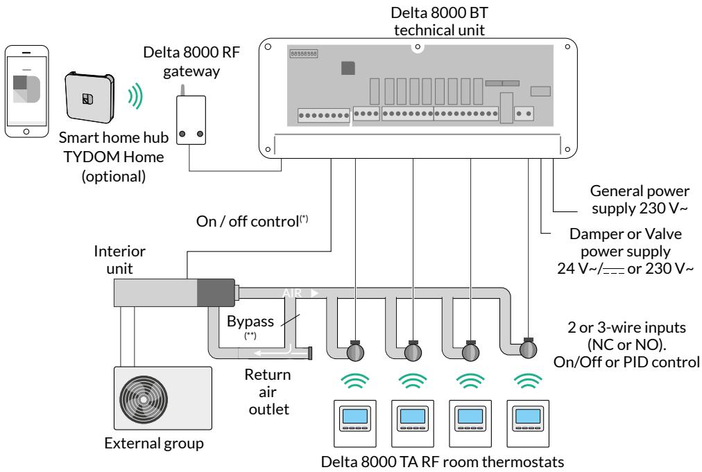
(*) The On/Off control cannot replace the generator's/boiler's short cycle protection.
(**) Because the Delta 8000 does not manage the air flow, it is necessary to implement a bypass in order to ensure constant pressure within the ductable system.
2/ Mounting and Connection
2.1 Delta 8000 BT
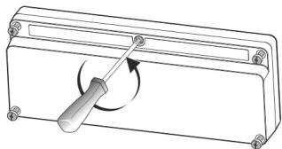
① Remove the cover and disconnect the electrical supply.
1
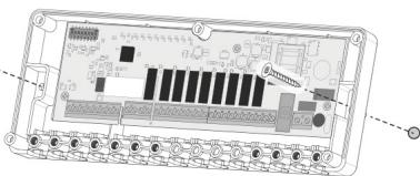
2 Mount the unit with a set of screws/sprigs compatible with the bracket (not included).
2
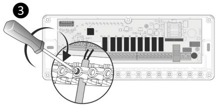
3 Connect the cables (refer to the 'connection' section). Tighten the clamp using the nylon screws supplied to secure the cable.
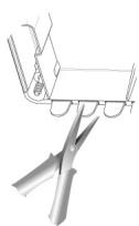
4 Remove the temporary partitions to run the cables to the required locations, then close the unit.
5 Reconnect the electrical supply.
4
2/ Mounting and Connection
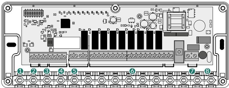

| Hydraulic | Aeraulic | |
| 1 (optional) | Water monitoring input | Not used |
| 2 (optional) | Change-over input or output (configurable) | |
| 3 | Bus outputs | |
| 4 (optional) | Circulator/Pump On/Off output | Not used |
| 5 (optional) | Generator/Boiler On/Off output | |
| 6 | Valve outputs | Register outputs |
| 7 | Valve supply | Register supply |
| 8 | General power supply 230 V~: - either via a circuit breaker in the consumer unit (H05VV-F cable) - or, via a 2x0.75 mm 2 H05VVH2-F cables with a 2-pole plug. | |
① Water monitoring input (option) by CTN sensor or dew point sensor (according to SW8 configuration)
② If your system controls the change-over (heating/cooling mode management), connect the change-over input or output (according to SW6 configuration):
| SW6 | OFF | Change-over input. From heat pump -> TU |
| ON | Change-over output. From TU-> heat pump |
- If configured as an "Input": Delta 8000 automatically switches from heating to cooling mode and vice versa depending on the information provided by the heat pump (output available depending on the heat pump model)
- If configured as an "Output": the Delta 8000 technical unit supplies the information concerning the current mode (heating/cooling) to the heat pump (input available depending on the heat pump model). Open circuit voltage < 28VDC, current < 50mA, consult our technical department.
3 To connect the Bus, use the cable supplied with the gateway (2x0.75 mm 2 , length 1 m) or a 2x0.75 mm 2 -cable with a max. length. 30 m.
- max. 4 wires maximum per terminal,
- Be sure to respect the + and - polarities,
- Room terminals can be connected to any one of the 2 Bus terminals.
4 5 Circulator/Pump and generator/boiler On/Off outputs, dry contact sec max. 2A, 230V\~
⑥ Valve or dampers outputs, max. 1A, 230V\~
| Valves | Registers |
| 2-wire actuators (SW3 OFF) | |
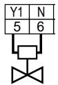 | 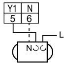 |
| Y1 (5): opening commandN (6): common (or neutral). | Neutral (6), switched phase (5) + permanent phase |
| 3-wire actuators (SW3 ON) | |
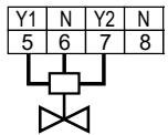 | 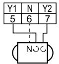 |
| Y1 (5): open commandN (6): common (or neutral)Y2 (7): close commandN (8): not used. | Neutral (6), open/closed switched phases (5 and 7) |
| SW4 | Valve/damper control direction | OFF | Normally closed |
| ON | Normally open |
A thermostat can control several outputs (CF20 parameter on the thermostat),
⑦ Power supply for valves or dampers 24 VAC/DC or 230 V\~ / 240 V\~.
8 Main power supply 230 V\~/240 V\~
2/ Mounting and Connection
2.2 Delta 8000 RF
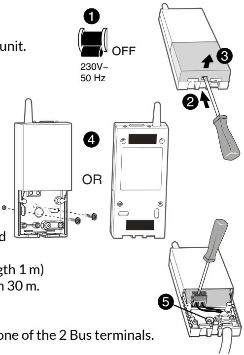
1 Disconnect the power to the technical unit.
② ③ Open the unit door by pushing the pin using a screwdriver.
4 Attach the base with fasteners compatible with the mount.
5 Connect the bus to the terminal located on the base.
Use the cable supplied (2x0.75 mm 2 , length 1 m) or a 2x0.75 mm 2 -cable with a max. length 30 m.
- 4 wires maximum per terminal.
- Be sure to respect the + and - polarities.
- The gateway can be connected to either one of the 2 Bus terminals.
6 Close the cover and switch the system back on.
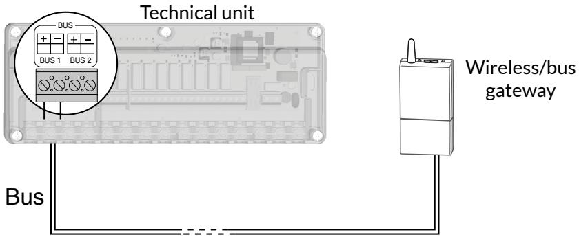
When switched on, the Delta 8000 RF is automatically recognised by the Delta 8000 BT.
2.3 Delta 8000 TA RF and TA Bus
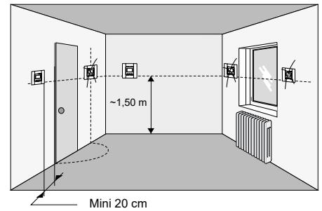
Since the temperature measurement sensor is inside the box, you must install the thermostat flush-mounting box:
- On an accessible wall at a height of 1.50 m
- Away from heat sources (fireplaces, sunlight) and draughts (windows, doors).
IMPORTANT: Do not install the thermostat on a wall in contact with the outdoors or with an unheated room (e.g. garage, etc.) The sleeve output in the flush-mounting box must be blanked off (with mastic) in order to avoid unwanted air movements that could bias the sensor reading.
2.3.1 Delta 8000 TA RF
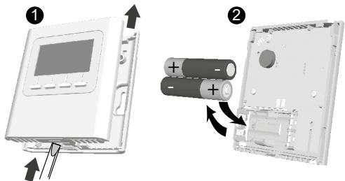
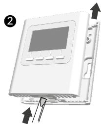
① Separate the unit from its base by pushing the pin using a screwdriver.
② When you use the batteries for the first time or replace them, insert them with the right polarity.
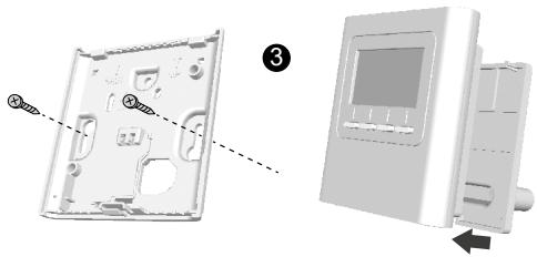
3 Wall mounting: attach the base to the wall using suitable screws and remount the unit onto its base.
Placed on furniture: reattach the table base to the unit, then mount the entire thing onto the table mount.
2/ Mounting and Connection
2.3.2 Delta 8000 TA BUS
1 Disconnect the power to the technical unit.
② Separate the unit from its base by pushing the pin using a screwdriver.
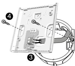
3 Connect the bus to the terminal located on the base, no polarity to be observed (2x0.75 mm 4 -cable with a max. length 30 m).
④ Mount the base to the flush-mounting box.
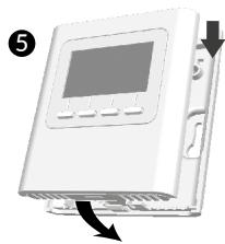
⑤ Refit the thermostat back on its base.
6 Restore the power to the installation.

3/ Pairing of peripheral products with the Delta 8000 TU
3.1 Pairing a Delta 8000 TA RF gateway
When switched on, the Delta 8000 RF is automatically recognised by the Delta 8000 BT.
3.2 Pairing a Delta 8000 TA RF
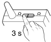
① On the gateway, Press and hold the left button for 3 seconds until LED 1 flashes. Release the button.
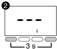
② On the thermostat, press and hold the 1st and the 4th buttons for 3 seconds, then release.
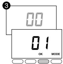
③ The display flashes, indicating the number of products found. When the flashing stops, press OK to confirm. LED 1 on the gateway stops flashing.
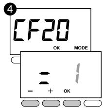
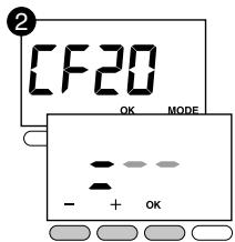
4 The display shows CF20. Press OK, then + and - to select the output to which the room thermostat will be paired. Confirm with OK.
| CF20 | Output number | 1 to 16 depending on the system |
Ensure that the output paired with each of your thermostats is clearly identified in order to rename them easily afterwards.
Example:

| Output numbers | Controlled outputs | |
| Thermostat 1 | 1 | Y1, Y2, Y3 |
| Thermostat 2 | 4 | Y4, Y5 |
| Thermostat 3 | 6 | Y6, Y7 |
| Thermostat 4 | 8 | Y8 |
3/ Pairing of peripheral products
with the Delta 8000 TU
⑤ The display shows CF21.
Select the transmitter and press OK.
| CF21 | Transmitter type | 0 | Underfloor heating |
| 1 | Heater | ||
| 2 | Ceiling or ductable |
⑥ The display shows CF05.
Select the transmitter and press OK.
| CFOS | Thermostat type | 0 | Zone thermostat (default selection) |
| 1 | Master thermostat |
The Master thermostat enables the centralised use of ON/OFF and HEATING/COOLING (at least one Master thermostat is required in an installation without a programmer or without the Tydom application).
| Temperature management | On/Off management | HEAT/COOL management | |
| Master thermostat | On the controlled zone | On all zones | On all zones |
| Zone thermostat | On the controlled zone | On the controlled zone | - |
Restart operations ① to ⑥ for each thermostat (Delta 8000 TA RF) to be paired.
3.3 Pairing a Delta 8000 TA Bus
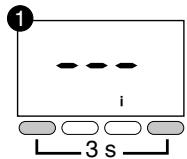
1 Press and hold the 1st and 4th buttons for 3 seconds, then release.
② The display shows CF20.
Press OK, then + and - to select the output(s) with which the room thermostat will be paired.
Confirm with OK.
| CF20 | Output number | 1 to 16 depending on the system |
(1) Example:

| Output number | Controlled outputs | |
| Thermostat 1 (Living room) | 1 | Y1, Y2, Y3 |
| Thermostat 2 (Loungeg) | 4 | Y4, Y5 |
| Thermostat 3 (Office) | 6 | Y6, Y7 |
| Thermostat 4 (Bedroom) | 8 | Y8 |
③ The display shows CF21.
Select the transmitter and press OK.
| CF21 | Transmitter type | 0 | Underfloor heating |
| 1 | Heater | ||
| 2 | Ceiling or ductable |
4 The display shows CF05.
Select the transmitter and press OK.
| CFOS(2) | Thermostat type | 0 | Zone thermostat (default selection) |
| 1 | Master thermostat |
The Master thermostat enables the centralised use of ON/OFF and HEATING/COOLING (at least one Master thermostat is required in an installation without a programmer or without TYDOM).
| Temperature management | On/Off management | HEAT/COOL management | |
| Master thermostat | On the controlled zone | On all zones | On all zones |
| Zone thermostat | On the controlled zone | On the controlled zone | - |
Restart operations ① to ⑥ for each thermostat (Delta 8000 TA Bus) to be paired.
4/ Switch configuration
All the switches are set to OFF by default.
Each change of switch position must be performed with the power disconnected in order to be taken into account.

Recommended configuration
| Hydraulic | Aeraulic | ||||
| SW1 | Configuring the technical unit | OFF | Master | ON or OFF | |
| ON | Slave (see the "Presentation of the system" section) | ||||
| SW2 | Production mode | OFF | Heat (boiler or non-reversible heat pump) | ON or OFF | ON |
| ON | Heating/Cooling (reversible heat pump) | ||||
| SW3 | Valve or register actuator type | OFF | Thermal 2 positions (number of outputs 8 max.) | ON or OFF | |
| ON | Motorised 3 positions (number of outputs 4 max.) | ||||
| SW4 | Valve or register control direction | OFF | Normally closed | ON or OFF | |
| ON | Normally open | ||||
| SW5 | Override mode (e.g: initial heating) | OFF | No | Reset to OFF after the test | |
| ON | Yes (valves and circulator active) | ||||
| SW6 | Heat pump change-over communication direction | OFF | Heat pump to Technical Unit (Change-over input). The heat pump delivers its production mode to the TU. | ON if terminal 2 is not connected. ON or OFF if terminal 2 is connected. | |
| ON | TU to heat pump (change-over output). The TU delivers its production mode to the heat pump. | ||||
| SW7 | Heat pump change-over configuration | OFF | Contact closed= Heating mode Contact open = Cooling mode | OFF if terminal 2 is not connected. ON or OFF if terminal 2 is connected. | |
| ON | Contact closed = Cooling mode Contact open = Heating mode | ||||
| SW8 | Type of 'water monitoring' measurement" | OFF | Lack of sensor or dew point measurement with Delta Dore condensation sensor. (In cooling mode only, system cuts out in case of condensation). | ON or OFF | OFF |
| ON | Cooling or Heating flow temperature with 10KΩ CTN temperature probe at 25°C. (System shuts down if the water is too hot or too cool). | ||||
SW5: Override mode
This mode overrides the 100% operation (example for initial heating).
Set switch 5 to ON.
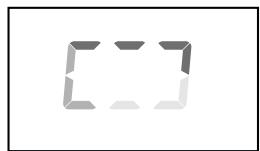
On the technical unit, the circulator LED and output LEDs are illuminated.
The 'Status' LED is off.
On the room thermostat (RT) or the programmable thermostat (PRT), a specific display indicates that initial heating is in progress.
5/ Description of the LEDs of the BT Delta 8000
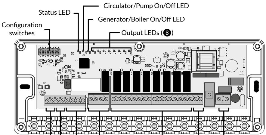
| LED status (green) | Circulator/Pump and generator/boiler On/Off LEDs (red) | Output LEDs (red) | |
| On | Normal operation | Relay closed Output on | On |
| Off | Override mode (e.g: initial heating) | Relay open Output off | Off |
| Slow flashing ......... | Pairing mode | - | Pending wireless pairing |
| Quick flashing | Defect in progress | - | Defect in progress |
6/ Technical Specifications
- Mains power supply 230 V\~/240 V\~, +/-10%, 50/60 Hz,
- Consumption: 2 to 15 VA (5,5W max.) depending on the number of elements connected to the bus and the number and type of controlled actuator (valves/ registers),
- Valve/register power supply (24V\~/= or 230V\~/240V\~): max. 4A on all valves/ registers (Accepted switch-on current: max. 6A),
- 8 powered contact outputs supplied for the control of the valves/registers: Continuous current: max. 1A per output, 230V\~/240V\~ +/-10%, Accepted switch-on current: max. 2A per output,
- 2 dry contact outputs controlling the burner and circulator (max. 2A per output, 230V\~/240V\~ +/-10%)
- 1 change-over input or output (according to SW6 configuration),
- 2 communication buses for connecting the thermostats (star cabling),
- Type 1.C action (micro-interruption),
- Class II insulation,
- Surface-mounted,
• Dimensions: 250 x 95 x 43 mm,
• Protection rating: IP 33, - Operating temperature: 0°C to +50°C ,
- Storage temperature: -10°C to +70°C ,
- Rated impulse withstand voltage: 2500Vac
- Installation in an environment with normal pollution levels,
- Anti-seize function (automatic start-up 1 to 10 minutes/week if the event that the valve and circulator remain idle).
CE
www.deltadore.com
04/24

2704571 Rev.03
- DELTA 8000 BT
- DETAILED ONLINE INSTRUCTIONS
- CONTENTS
- 1/ SYSTEM PRESENTATION
- 1.1 PRESENTATION
- 1.2 INSTALLATION DIAGRAMS
- 1/ PRESENTATION OF THE SYSTEM
- 1.2.2 EXAMPLE OF AN AERAULIC APPLICATION WITH WIRELESS THERMOSTATS
- 2/ MOUNTING AND CONNECTION
- 2.1 DELTA 8000 BT
- 2.2 DELTA 8000 RF
- 2.3 DELTA 8000 TA RF AND TA BUS
- 2.3.1 DELTA 8000 TA RF
- 2.3.2 DELTA 8000 TA BUS
- 3/ PAIRING OF PERIPHERAL PRODUCTS WITH THE DELTA 8000 TU
- 3.1 PAIRING A DELTA 8000 TA RF GATEWAY
- 3.2 PAIRING A DELTA 8000 TA RF
- 3/ PAIRING OF PERIPHERAL PRODUCTS
- WITH THE DELTA 8000 TU
- ⑤ THE DISPLAY SHOWS CF21
- ⑥ THE DISPLAY SHOWS CF05
- 3.3 PAIRING A DELTA 8000 TA BUS
- ③ THE DISPLAY SHOWS CF21
- 4 THE DISPLAY SHOWS CF05
- 4/ SWITCH CONFIGURATION
- 5/ DESCRIPTION OF THE LEDS OF THE BT DELTA 8000
- 6/ TECHNICAL SPECIFICATIONS
Marque : DELTA DORE
Modèle : Delta 8000 BT
Catégorie : Automatisme domotique