
GX-700 - Multi-effets pour guitare BOSS - Notice d'utilisation et mode d'emploi gratuit
Retrouvez gratuitement la notice de l'appareil GX-700 BOSS au format PDF.
| Type de produit | Processeur multi-effets pour guitare rackable |
| Dimensions | 482 x 197 x 44 mm (EIA-1U) |
| Poids | 2.0 kg (hors adaptateur secteur) |
| Alimentation | Adaptateur secteur AC 14 V (BOSS BRC-120/230/240) |
| Consommation électrique | 800 mA |
| Conversion AD/DA | 22 bits AF / 18 bits 16x suréchantillonnage |
| Fréquence d'échantillonnage | 44.1 kHz |
| Mémoires de patches | 200 (100 utilisateur + 100 preset) |
| Entrées | Jack INPUT (avant et arrière), RETURN, Expression Pedal, CONTROL 1/2 |
| Sorties | OUTPUT L/MONO et R, SEND, casque |
| MIDI | IN, OUT, THRU |
| Effets intégrés | Compresseur, Wah, Overdrive/Distortion, Préampli, Boucle d'effets, Égaliseur 3 bandes, Simulateur de haut-parleur, Suppresseur de bruit, Modulation (Flanger, Phaser, Pitch Shifter, Harmonist, Vibrato, Ring Modulator, Humanizer), Delay, Chorus, Tremolo/Pan, Reverb |
| Fonctions spéciales | Circuit de distorsion analogique, Harmonist à 4 voix, Accordeur chromatique intégré, affectation de contrôle, ordre des effets libre |
| Accessoires fournis | Manuel d'utilisation, adaptateur secteur BOSS BRC-120/230/240 |
| Entretien et nettoyage | Nettoyer avec un chiffon doux sec ou légèrement humide ; ne pas utiliser de solvants |
| Sécurité | Ne pas ouvrir, utiliser sur une surface stable, éviter l'humidité |
FOIRE AUX QUESTIONS - GX-700 BOSS
Questions des utilisateurs sur GX-700 BOSS
0 question sur cet appareil. Repondez a celles que vous connaissez ou posez la votre.
Poser une nouvelle question sur cet appareil
Téléchargez la notice de votre Multi-effets pour guitare au format PDF gratuitement ! Retrouvez votre notice GX-700 - BOSS et reprennez votre appareil électronique en main. Sur cette page sont publiés tous les documents nécessaires à l'utilisation de votre appareil GX-700 de la marque BOSS.
MODE D'EMPLOI GX-700 BOSS
GX-700
GUITAR EFFECTS PROCESSOR
Owner's Manual
USING THE UNIT SAFELY
INSTRUCTIONS FOR THE PREVENTION OF FIRE, ELECTRIC SHOCK, OR INJURY TO PERSONS
About WARNING and CAUTION Notices
| △WARNING | Used for instructions intended to alert the user to the risk of death or severe injury should the unit be used improperly. |
| △CAUTION | Used for instructions intended to alert the user to the risk of injury or material damage should the unit be used improperly. * Material damage refers to damage or other adverse effects caused with respect to the home and all its furnishings, as well to domestic animals or pets. |
About the Symbols
| A | The △ symbol alerts the user to important instructions or warnings. The specific meaning of the symbol is determined by the design contained within the triangle. In the case of the symbol at left, it is used for general cautions, warnings, or alerts to danger. |
| B | The ○ symbol alerts the user to items that must never be carried out (are forbidden). The specific thing that must not be done is indicated by the design contained within the circle. In the case of the symbol at left, it means that the unit must never be disassembled. |
| C | The ● symbol alerts the user to things that must be carried out. The specific thing that must be done is indicated by the design contained within the circle. In the case of the symbol at left, it means that the power cord plug must be unplugged from the outlet. |
ALWAYS OBSERVE THE FOLLOWING
WARNING
- Do not open (or modify in any way) the unit or its AC adaptor.

- Do not attempt to repair the unit, or replace parts within it (except when this manual provides specific instructions directing you to do so). Refer all servicing to your dealer, or qualified Roland service personnel.

- Never use or store the unit in places that are:
- Subject to temperature extremes (e.g., direct sunlight in an enclosed vehicle, near a heating duct, on top of heat-generating equipment); or
- Use in areas where the unit is intended for storage.

- Damp (e.g., baths, washrooms, on wet floors); or are
- Humid; or are
Dusty; or are -
Subject to high levels of vibration.
-
This unit should be used only with a rack or stand that is recommended by Roland.

- When using the unit with a rack or stand recommended by Roland, the rack or stand must be carefully placed so it is level and sure to remain stable. If not using a rack or stand, you still need to make sure that any location you choose for placing the unit provides a level surface that will properly support the unit, and keep it from wobbling.

- Avoid damaging the power cord. Do not bend it excessively, step on it, place heavy objects on it, etc. A damaged cord can easily become a shock or fire hazard. Never use a power cord after it has been damaged.

- Do not allow any objects (e.g., flammable material, coins, pins); or liquids of any kind (water, soft drinks, etc.) to penetrate the unit.

WARNING
- Immediately turn the power off, remove the AC adaptor from the outlet, and request servicing by your dealer or qualified Roland service personnel when:

- The AC adaptor, the power-supply cord, or the plug has been damaged; or
- Objects have fallen into, or liquid has been spilled onto the unit; or
The unit has been exposed to rain (or otherwise has become wet); or -
The unit does not appear to operate normally or exhibits a marked change in performance.
-
In households with small children, an adult should provide supervision until the child is capable of following all the rules essential for the safe operation of the unit.

- Protect the unit from strong impact. (Do not drop it!)

- Do not force the unit's power-supply cord to share an outlet with an unreasonable number of other devices. Be especially careful when using extension cords—the total power used by all devices you have connected to the extension cord's outlet must never exceed the power rating (watts/amperes) for the extension cord. Excessive loads can cause the insulation on the cord to heat up and eventually melt through.

- Before using the unit in a foreign country, consult with your dealer, or qualified Roland service personnel.

| △CAUTION | △CAUTION |
| ·The unit and the AC adaptor should be located so their location or position does not interfere with their proper ventilation. | |
| ·Always grasp only the plug on the AC adaptor cord when plugging into, or unplugging from, an outlet or this unit. | |
| ·Whenever the unit is to remain unused for an extended period of time, disconnect the AC adaptor. | |
| ·Try to prevent cords and cables from becoming entangled. Also, all cords and cables should be placed so they are out of the reach of children. | |
| ·Never climb on top of, nor place heavy objects on the unit. | |
| ·Never handle the AC adaptor or its plugs with wet hands when plugging into, or unplugging from, an outlet or this unit. | |
| ·Before moving the unit, disconnect the AC adaptor and all cords coming from external devices. | |
| ·Before cleaning the unit, turn off the power and unplug the AC adaptor from the outlet (p. 10). | |
| ·Whenever you suspect the possibility of lightning in your area, disconnect the AC adaptor from the outlet. |
Introduction
Thank you for purchasing the BOSS GX-700 Guitar Effects Processor. In order to take full advantage of the GX-700's functionality, and enjoy long years of trouble-free use, please read this manual carefully.
Before using this unit, carefully read the sections entitled: "USING THE UNIT SAFELY" and "Important Notes" (p.2-3; p.6). These sections provide important information concerning the proper operation of the unit. Additionally, in order to feel assured that you have gained a good grasp of every feature provided by your new unit, this manual should be read in its entirety. The manual should be saved and kept on hand as a convenient reference.
Main Features
Analog distortion circuit
The distortion effects in the GX-700 use analog circuitry, providing the most powerful distortion available from BOSS.
Preamp Built-In
The built-in digital preamp simulates the response of a guitar amplifier. Simulations are provided for a variety of classic guitar amps, allowing you to create the perfect sound for your system.
Speaker Simulator Built-In
The built-in speaker simulator is especially effective for line-level recording. You can specify the type of the speaker box and the location of the microphone, and use the result for line recording.
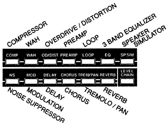
Illuminated Buttons
Buttons corresponding to each of the internal effects are offered right on the front panel, allowing you to see the on/off status of each effects processor at a glance.
Designed for Compact Efficiency
All effects can be connected in any order desired, including external effects. Thanks to this, you can set up the unit to suit your particular style, and play just like you would with individual compact effects units.
Operation is also efficient and uncomplicated. Directly specify the effects processor you wish to use, then tweak its parameters to create just the sound you want.
A "Harmonist" Generates Four-Note Harmony
The harmonist function adds to the sound of the guitar a harmony of up to three additional notes geared to the key (scale) in which you are playing.
Chromatic Tuner Built-In
The built-in chromatic tuner displays the string names, and can even handle tunings lowered by a half step. During tuning, the illuminated buttons also indicate tuning deviation, allowing you to tune even when at a distance from the GX-700.
100 User Area Settings
Memory provides a total of 200 effect sounds (100 user, 100 preset). Effect sounds can be recalled instantly from the front panel or by using MIDI program changes.
A Roland FC-200 MIDI Foot Controller (optional) is ideally suited for use with the GX-700, and allows you to select effect sounds and control parameters in real time.
Contents
Using the Unit Safely 2
Introduction 4
Main Features 4
Important Notes 6
How the GX-700 Is Organized. 7
How to Use This Manual 7
Panel Descriptions 8
Section 1 Try out the GX-700. 9
Connections 9
Power-on and Standby 10
Power-on 10
Adjusting the Input Level 11
Adjusting the Output Level 11
Settings for connected equipment 11
Selecting an Effect Sound 12
About the Screen Display 12
About the Effect Select button display 12
Selecting Effect Sounds from the Front Panel 12
Selecting Effect Sounds with a Foot Switch 12
Selecting Effect Sounds with an FC-200 MIDI Foot Controller .... 13
Selecting Effect Sounds by MIDI Messages 13
Switching Bypass On/Off 13
Switching Bypass On/Off from the Panel 13
Switching Bypass On/Off from a Footswitch 13
Switching Bypass On/Off from an FC-200 MIDI Foot Controller...13
Switching Bypass On/Off by MIDI Messages 13
Using the Tuner 14
Switching to the Tuner Function 14
About the Display During Tuning 14
Tuning Procedure 15
Tuner Settings 15
Section 2 Modifying various settings ....17
Before You Begin Creating Sounds. 17
User Area and Preset Area 17
What a Patch Contains 17
About the Contents of the Display 18
Sound Editing Procedure 18
Copying and Exchanging Effect Sounds 19
Effect Sound Settings 19
Effect On/Off Settings 19
Setting the Effect Unit Connection Order 20
Settings for Each Effects Processor 21
Level Meter 22
Effect Copy 22
Modifying the Patch Name 23
Control Assign Settings 23
Setting the Output Level 26
Canceling Changes and Restoring Edited Data 26
Storing the Modified Settings (The Write Operation) ....27
Utility Function Settings. 28
Section 3 Effect Guide 32
COMPRESSOR 32
WAH 33
OVERDRIVE / DISTORTION 35
PREAMP 36
LOOP 37
3BAND EQUALIZER 37
SPEAKER SIMULATOR 38
NOISE SUPPRESSOR 39
MODULATION 39
FLANGER. 40
PHASER 40
PITCH SHIFTER 41
HARMONIST 41
VIBRATO 43
RING MODULATOR 43
HUMANIZER 43
DELAY 44
CHORUS 47
TREMOLOPAN 48
REVERB 49
Section 4 Using MIDI 50
How MIDI Can Be Used 50
Operations from External MIDI Devices 50
MIDI Utility Function Settings 51
MIDI Related Parameters 51
Program Change Map Settings 52
Transmitting / Receiving Data Via MIDI 52
Transmitting Data (Bulk Dump) 52
Receiving Data (Bulk Load) 53
Section 5 Appendix 55
GX-700 Operation Using the FC-200 55
GX-700 and FC-200 Connections 55
Selecting Patches from the FC-200 56
Control Assign Operations Using the FC-200 57
Manual mode (switching effects on/off) 58
No-Hands Editing (Using the FC-200 to Create Sounds)....58
About MIDI. 59
-
How MIDI messages are transmitted and received ....59
-
Main types of MIDI message used by the GX-700.....59
About the MIDI Implementation Chart 60
Initializing the FC-200 from the GX-700 60
Restoring the Factory Settings (Initialization) 61
Troubleshooting 62
MIDI Implementation Chart 63
Specifications 64
Index 65
Important Notes
In addition to the items listed under "USING THE UNIT SAFELY" on page 2-3, please read and observe the following:
Power Supply
- Do not use this unit on the same power circuit with any device that will generate line noise (such as an electric motor or variable lighting system).
- The AC adaptor will begin to generate heat after long hours of consecutive use. This is normal, and is not a cause for concern.
- Before connecting this unit to other devices, turn off the power to all units. This will help prevent malfunctions and/or damage to speakers or other devices.
Placement
- Using the unit near power amplifiers (or other equipment containing large power transformers) may induce hum. To alleviate the problem, change the orientation of this unit; or move it farther away from the source of interference.
- This device may interfere with radio and television reception. Do not use this device in the vicinity of such receivers.
- Do not expose the unit to direct sunlight, place it near devices that radiate heat, leave it inside an enclosed vehicle, or otherwise subject it to temperature extremes. Excessive heat can deform or discolor the unit.
Maintenance
- For everyday cleaning wipe the unit with a soft, dry cloth or one that has been slightly dampened with water. To remove stubborn dirt, use a mild, non-abrasive detergent. Afterwards, be sure to wipe the unit thoroughly with a soft, dry cloth.
- Never use benzene, thinners, alcohol or solvents of any kind, to avoid the possibility of discoloration and/or deformation.
Repairs and Data
- Please be aware that all data contained in the unit's memory may be lost when the unit is sent for repairs. Important data should always be backed up in another MIDI device (e.g., a sequencer), or written down on paper (when possible). During repairs, due care is taken to avoid the loss of data. However, in certain cases (such as when circuitry related to memory itself is out of order), we regret that it may not be possible to restore the data, and Roland assumes no liability concerning such loss of data.
Memory Backup
- This unit contains a battery which powers the unit's memory circuits while the main power is off. When this battery becomes weak, the message shown below will appear in the display. Once you see this message, have the battery replaced with a fresh one as soon as possible to avoid the loss of all data in memory. To have the battery replaced, consult with your dealer, or qualified Roland service personnel.
Battery Low !! Please Change
Additional Precautions
- Please be aware that the contents of memory can be irretrievably lost as a result of a malfunction, or the improper operation of the unit. To protect yourself against the risk of loosing important data, we recommend that you periodically save a backup copy of important data you have stored in the unit's memory in another MIDI device (e.g., a sequencer).
- Unfortunately, it may be impossible to restore the contents of data that was stored in the unit's memory once it has been lost. Roland Corporation assumes no liability concerning such loss of data.
- Use a reasonable amount of care when using the unit's buttons, sliders, or other controls; and when using its jacks and connectors. Rough handling can lead to malfunctions.
- When connecting / disconnecting all cables, grasp the connector itself—never pull on the cable. This way you will avoid causing shorts, or damage to the cable's internal elements.
- To avoid disturbing your neighbors, try to keep the unit's volume at reasonable levels. You may prefer to use headphones, so you do not need to be concerned about those around you (especially when it is late at night).
- When you need to transport the unit, package it in the box (including padding) that it came in, if possible. Otherwise, you will need to use equivalent packaging materials.
How the GX-700 Is Organized
The easiest way to understand the GX-700 is to think of it as a large set of compact effect devices packaged into a rackmountable box.
During normal use, you can select from 200 different sets of effects devices, which are already arranged in a certain order and have appropriate settings made.
To create a new effect sound, you select the effects that you wish to use, specify the order in which they are connected, and then set the knobs for each effects device.
How to Use This Manual
This manual explains the procedures and functions used for normal playing, and how to make various settings. It is divided into five major sections. Read each section as necessary.
At the end of the manual an alphabetical index is provided. If you have questions about operation, refer to the index.
Section 1 Try out the GX-700
This section explains the basic operation of the GX-700, such as connecting the GX-700 with external devices, and selecting from the effect sounds stored in the GX-700's memory.
Section 2 Modifying Various Settings
This section explains how to modify effect sound settings. Read this section when you wish to change the settings of various functions.
Section 3 Effect Guide
This section explains the function of the effect parameters.
Section 4 Using MIDI
This section explains how external MIDI devices can be used to control the GX-700, and how data can be transmitted and received via MIDI. Read this section when you wish to use the MIDI functions of the GX-700.
Section 5 Appendix
This section explains operations using the FC-200 MIDI Foot Controller (optional). It also contains material that will help you get the most out of your GX-700, lists of the factory settings, and a helpful troubleshooting section.
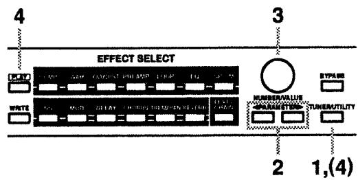
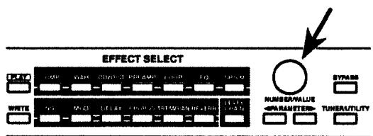
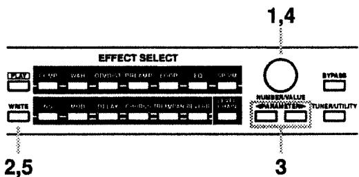
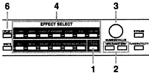
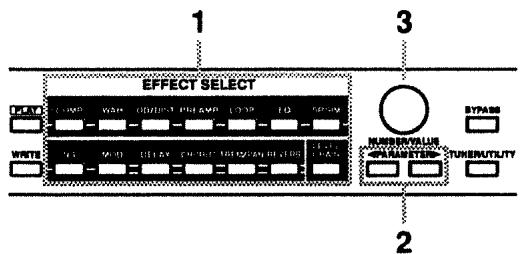
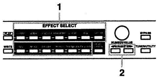
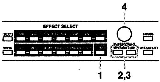
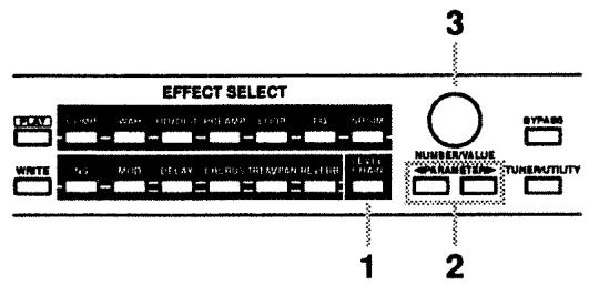
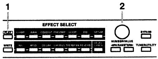
Panel Descriptions
< Front Panel >
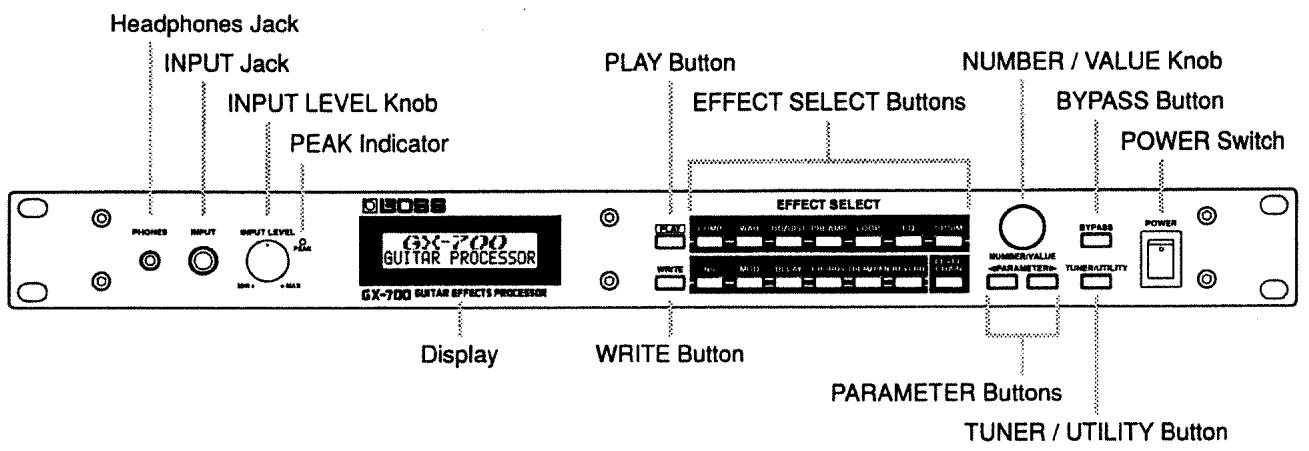
* In this manual, the number/value knob is referred to as either the NUMBER knob or as the VALUE knob.
Section
1
Try out the GX-700
Connections
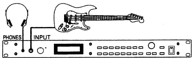
First, connect up the guitar and guitar amplifier with the GX700 as shown below, then connect the supplied AC adaptor.
- To prevent malfunction and/or damage to speakers or other devices, always turn down the volume, and turn off the power on all devices before making any connections.
- The volume on your amplifier should be turned up only after switching on all the other units.
- To output in monaural, connect a cable to only the OUTPUT L (MONO) jack.
- For an expression pedal (optional), be sure to use either a Boss FV-300L + PCS-33 (Roland) or an EV-5 (Roland).
- Set the minimum volume on the expression pedal connected to the EXP PEDAL jack to the "MIN" position.
- INPUT jacks for your guitar are provided on the front panel and also on the rear panel. If both are connected, only the INPUT jack on the front panel will function.
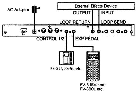
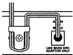
* To prevent the inadvertent disruption of power to your unit (should the plug be pulled out accidentally), and to avoid applying undue stress to the AC adaptor jack, anchor the power cord using the cord hook, as shown in the illustration.
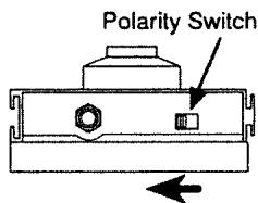
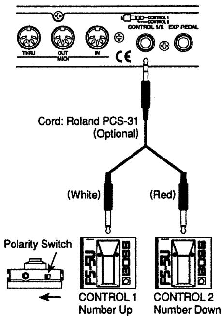
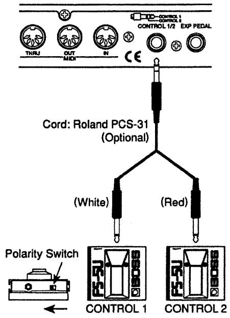
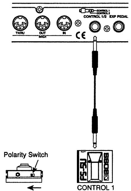
* If connecting a footswitch (FS-5U; optional) to the CONTROL 1/2 jack, set the polarity switch as shown below.
Power-on and Standby
In order to take full advantage of the GX-700's performance, be sure to make the following settings.
Power-on
Once the connections have been completed (p. 9 - 10), turn on power to your various devices in the order specified. By turning on devices in the wrong order, you risk causing malfunction and/or damage to speakers and other devices.
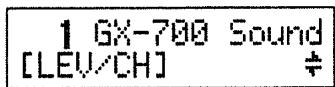
The following display will appear, and after several seconds, the GX-700 will be ready for normal playing. This display is referred to as the "Play page."
- Turn up the amp volume only after all devices have been powered on.
- When the power is turned on, the last-selected Patch number will be selected.
- This unit is equipped with a protection circuit. A brief interval (a few seconds) after power up is required before the unit will operate normally.
- Depending on the location where the GX-700 is placed, the display may be difficult to read. In this case, adjust the display contrast (p. 30).
Adjusting the Input Level
The level of the output signal differs between guitars. Use the Input Level knob to adjust the input level to suit your guitar.
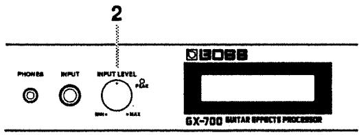
1 Play your guitar at the maximum loudness that you will produce in normal playing.
2 Adjust the Input Level knob until the PEAK Indicator lights briefly.
- The peak indicator will light 6 dB before clipping level (the level where distortion begins).
- If the input level is too high, the GX-700 will not produce the desired effects.
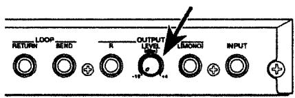
Adjusting the Output Level
Adjust the output level as appropriate for the devices to which the GX-700 is connected.
- Ordinarily, the Level Knob should be set at "-10 dBm."
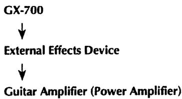
Settings for connected equipment
Specify the type of the equipment that is connected to the output jack.
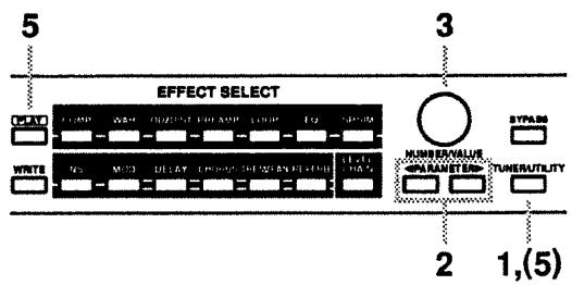
(Procedure)
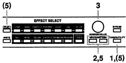
1 Press [TUNER/UTILITY].
The button indicator will light, and the tuner screen will appear in the display.
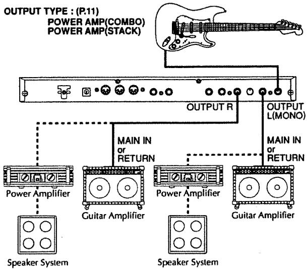
2 Use PARAMETER[←][▶] to access the following parameter in the display (OUTPUT TYPE).
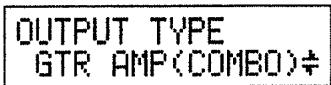
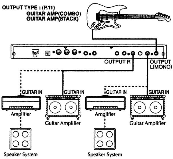
3 Use the VALUE knob to select the type of device which is connected to the output jack.
GUITAR AMP (COMBO):
Use this setting when connecting to the guitar input of a combo-type guitar amp (i.e., amp and speaker contained in a single unit).
GUITAR AMP (STACK):
Use this setting when connecting to the guitar input of a stack-type guitar amp (i.e., amp and speaker in separate units).
POWER AMP (COMBO):
Use this setting when connecting to the RETURN or MAIN IN of a combo-type guitar amp.
POWER AMP (STACK):
Use this setting when connecting to a power amp and speaker box, or to the RETURN or MAIN IN of a stack-type guitar amp.
LINE:
Use this setting when connecting to a mixer or MTR. This setting is also used when using headphones.
4 Press [PLAY] or [TUNER/UTILITY] to end the procedure.
Selecting an Effect Sound
Effect sounds are organized as Patch numbers 1 - 200. To select an effect sound, use the front panel or a MIDI device to change the Patch number.
Patch numbers can be selected only when the Play page (the screen display that shows the Patch number) is shown. If something other than the Play page is shown in the display, press [PLAY] to return to the Play page.
- The Patch immediately before Patch number 1 will be indicated as UNDO. This Patch contains the modifications that were last made. For details refer to "Canceling Changes and Restoring Edited Data" (p.26).
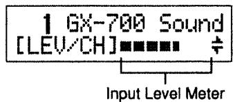
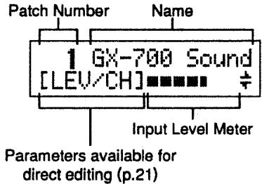
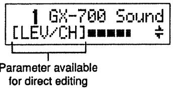
About the Screen Display
The following types of information are shown in the Play page.
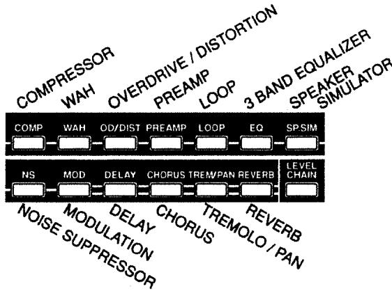
About the Effect Select button display
The effect select buttons corresponding to each effect will be lit or dark to indicate the effect on/off settings of each Patch number.
Selecting Effect Sounds from the Front Panel
Rotate the NUMBER knob.
As you rotate it to the right, successively higher Patch numbers will be selected. Rotating it to the left will select lower Patch numbers. When a Patch number is selected, the effect sound will change, and the name of the selected Patch number will be displayed.
- If you press the NUMBER knob as you rotate it, the Patch numbers will change more rapidly.
Selecting Effect Sounds with a Foot Switch
If an FS-5U foot switch (optional) is connected to the Control 1/2 jack, you can change Patch numbers by operating the foot switch.
- If you wish to use this function, make the following settings. For details refer to "CONTROL 1/2 JACK" (p.29).
CONTROL 1 JACK: NUMBER UP
CONTROL 2 JACK: NUMBER DOWN
- When using a foot switch, be aware that holding down the foot switch will not cause the Patch numbers to continue changing in succession.
- When using a foot switch to change Patches, you may specify the range of Patches that can be selected. For details refer to "NUMBER UP/DOWN" (p.30).
If you use two foot switches, you can select Patches by foot in the same way as by rotating the NUMBER knob.
If you use only one foot switch, you can use it to move either up or down (not both) through the Patch numbers.

Selecting Effect Sounds with an FC-200 MIDI Foot Controller
If an FC-200 MIDI Foot Controller (optional) is connected, you can switch Patch numbers by pedal operations on the controller. For details refer to "GX-700 Operation Using the FC-200" (p.55).
Selecting Effect Sounds by MIDI Messages
GX-700 Patches can be selected by Program Change messages from an external MIDI device. The correspondence between program numbers and GX-700 Patch numbers can be changed by modifying the settings of the Program Change Map (p.52).
Switching Bypass On/Off
You can switch the effect sound on/off. When an Bypass is on, the input sound will be output without modification.
- Bypass On/Off can be changed to a Mute function. For details refer to "BYPASS MODE" (p.30).
Switching Bypass On/Off from the Panel
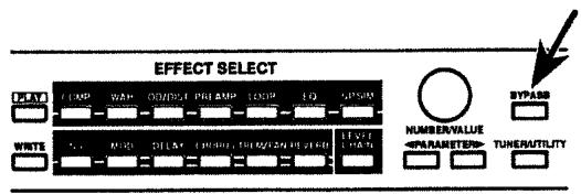
Bypass is turned ON and OFF by pressing the panel's [BYPASS]. Bypass is ON when the button's indicator is lit.
Switching Bypass On/Off from a Footswitch
If a separately available BOSS FS-5U foot switch is connected, you can switch bypass on/off in the following two ways. The same as when you press [BYPASS], the button's indicator is lit when switched on.
- If you wish to use this function, make the following settings. For details refer to "CONTROL 1/2 JACK" (p.29).
CONTROL 1 JACK: BYPASS
or
CONTROL 2 JACK: BYPASS
Switching Bypass On/Off from an FC-200 MIDI Foot Controller
If an FC-200 MIDI foot controller (optional) is connected, you can use pedal operations to switch bypass on/off. For details refer to "GX-700 Operation Using the FC-200" (p.55).
Switching Bypass On/Off by MIDI Messages
MIDI Control Change messages can be used to switch bypass on/off. For details refer to "Control Assign Settings" (p.23).
Using the Tuner
The GX-700 has a built-in chromatic tuner. You can tune your instrument quickly without having to change connections.
In addition to displaying the note name, the built-in tuner shows the string name, and allows you to make settings for (double-) flat tunings and to adjust the output level.
Switching to the Tuner Function
Here's how to use the built-in tuner to tune your guitar. While the tuner function is being used, the GX-700 will be muted, and the guitar sound will not be output.
- It is also possible to output the direct sound even while the tuner is being used. For details refer to "Volume settings during tuning" (p. 16).
< Switching from the Front Panel >
Each time you press [TUNER/UTILITY] the Tuner function will alternate on/off. When the tuner is on, the button indicator will light, and the tuner display will appear.
< Switching with a Foot Switch >
If an FS-5U is connected to the CONTROL 1/2 jack, you can switch the TUNER on/off with the foot switch. The same as when you press [TUNER/UTILITY], the button indicator will light when the tuner is on.
- If you wish to use this function, make the following settings. For details refer to "CONTROL 1/2 JACK" (p. 29).
CONTROL 1 JACK: TUNER
or
CONTROL 2 JACK: TUNER
< Switching with an FC-200 MIDI Foot Controller >
If an FC-200 MIDI Foot Controller (optional) is connected, you can switch the tuner on/off by pedal operations on the controller. For details refer to "GX-700 Operation Using the FC-200" (p. 55).
< Switching with MIDI Messages >
MIDI Control Change messages can be used to switch the Tuner on/off. For details refer to "Control Assign Settings" (p. 23).
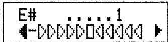
About the Display During Tuning
The GX-700's built-in tuner shows the note name in the upper line of the display, and the lower line shows a graphical tuning guide to indicate the sharpness or flatness of the note.
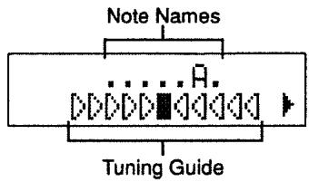
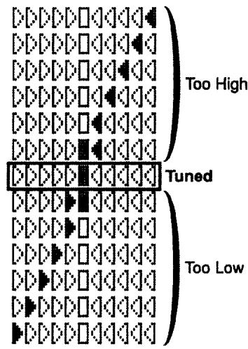
If the pitch deviation is within +/-50 cents, the tuning guide will indicate the amount of deviation. While watching the tuning guide, adjust the tuning until only the middle indicator (Tuned) is lit.
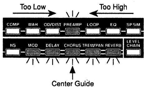
On the GX-700, the tuning guide is displayed using the effect select button indicators in addition to being shown in the display screen.
Tuning Procedure
1 Play a single unfretted note on the string you wish to tune.
The note name closest to the string you played will appear in the display.
- Cleanly play a single note only on the string that you wish to tune.
2 Adjust the tuning until the note name of the string you played appears in the display.
Standard Tuning
| 6th String | 5th String | 4th String | 3rd String | 2nd String | 1st String | |
| GUITAR | E | A | D | G | B | E |
3 While watching the tuning guide, adjust the tuning until only the middle indicator (Tuned) is lit.
4 Repeat steps 1 - 3 to tune all the strings.
- When tuning a guitar that has a tremolo arm, tuning one string may cause the other strings to go out of tune. In such cases, first tune the strings to the approximate pitch (so that the note name is displayed), and then keep tuning each string until they are all in tune.
Tuner Settings
Here you can make tunes settings. Make settings as appropriate for the way that you wish to use this function. The following items can be set.
Standard pitch setting
- String name display setting
Volume setting during tuning
(Procedure)
Each of the tuner settings can be made using the following procedure.
1 Press [TUNER/UTILITY] so that the Tuner page appears in the display.
2 Press PARAMETER [←][▶] so that the item that you wish to set appears in the display.
3 Use the VALUE knob to modify the setting.
4 Repeat steps 2-3 to modify the setting of the desired items.
5 Either use PARAMETER [][] to return to the tuner page, or press [PLAY] or [TUNER/UTILITY] to end the procedure. (You will return to the Play page.)
(Standard pitch settings) (435 - 445)
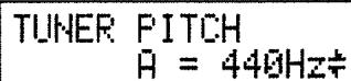
"Standard pitch" is the frequency of the A4 note (middle A on a piano) that is used as a standard to which all other notes are tuned. The GX-700 allows you to set the standard pitch over the range of 435 - 455 Hz.
- At the factory settings, this is set to 440Hz .
(String name display setting) (OFF, ON, ON () , ON ( ) )
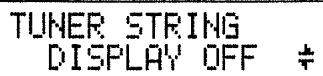
Selects whether or not the string names will be shown in the display. Also, if the string names are shown, you can select between regular tuning and flat (or double-flat) tuning.
< About the String Name Display >
This function indicates the un-fretted string that should correspond to the un-fretted note you played. When this function is used, you can match the string name (string number) being tuned with the string name shown in the display, and then tune so that only the center tuning guide is lit. This is convenient when changing strings, etc.
< About Flat (Double-Flat) Tuning >
Flat tuning refers to a tuning that is overall a semitone lower than regular tuning.
By selecting flat tuning on the GX-700, you can tune your guitar a semitone lower than regular tuning and still use the tuner function as usual. The contents of the display will be as normal, but the pitch will be a semitone lower, allowing you to tune as usual without having to be conscious of the difference. If you select double flat tuning, the pitch will be a whole step lower than normal.
OFF: The string name will not be shown.
ON: The string name for regular tuning will be shown.
ON () : The string name for flat tuning will be shown.
ON ( ) : The string name for double-flat tuning will be shown.
When the string name is shown, the display will be as follows.
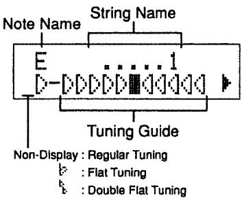
- If the pitch is more than 50 cents away from the correct pitch, the triangular symbol in the lower left of the display will appear solid (▲). When the pitch is within +/−50 cents of the correct pitch, the deviation will be indicated in the tuning guide, and the triangular symbol will change to only in outline form ([y]).
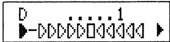
- Normally, the triangular symbol located in the lower left will be pointing to the right. However when the first string is being tuned and the pitch is more than 50 cents higher than the correct pitch, it will point to the left.
- Be sure to tune by playing open strings. If you play a harmonic, the correct string name may not be displayed.
- At the factory settings, "OFF" is selected.
(Volume settings during tuning) (MUTE - 100)
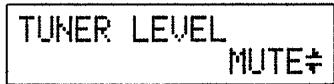
Set the volume that will be used during tuning.
- With the factory settings, "MUTE" is selected.
Section
2
Modifying various settings
On the GX-700, the settings that determine the connection order of the internal effects processors and the settings for each processor are collectively known as a "Patch number." The GX-700 contains 200 Patch numbers. This section explains how to edit the contents of a Patch number to create a new effect sound, and then store your new settings.
Before You Begin Creating Sounds
Before you begin creating sounds there are several things that you need to understand.
User Area and Preset Area
The 200 Patches in the GX-700 are divided into the User area and the Preset area.
User area (Patch numbers 1 - 100)
Patch numbers in the User area can be used to store effect sounds that you create.
Preset area (Patch numbers 101 - 200)
Patch numbers in the Preset area cannot store effect sounds that you create. However, you can start with a Preset area Patch, and modify and store it in the User area.
- Independently from the Preset area, the User area contains a Patch labeled "UNDO" which is located immediately before Patch number "1." This Patch contains the last-edited settings. For details refer to "Canceling Changes and Restoring Edited Data" (p.26).
What a Patch Contains
Each Patch number in the User area contains the following settings.
- Connection order of the effects processors
- On/off of each effects processor
- Settings for each effects processor
Output level setting - Control assign (4 types)
Name
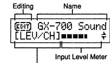
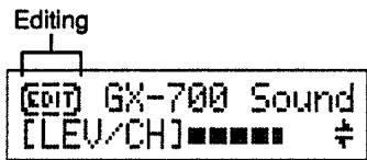
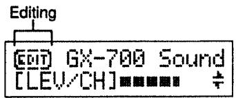
About the Contents of the Display
The following information appears in the display during editing.
< When (PLAY) Is Pressed to Access the Play Page >
Parameter available for direct editing (P.21)
Indicates that pressing PARAMETER [▶] will switch parameters.
Indicates that pressing PARAMETER [ ] will switch parameters.
: Indicates that pressing PARAMETER [or] will switch parameters.
Sound Editing Procedure
1 Select a Patch that is close to the effect sound you want to create.
2 Copy the contents of the selected Patch number to an unneeded Patch number (in the User area). (p.19)
- If you wish to modify the contents of the Patch number selected in step 1, there is no need to copy the data.
3 Modify the contents of the copied (selected) patch number.
3-1 Modify the connection order of the effect devices (p.20).
3-2 Modify the on/off setting of each effect device (p.19).
3-3 Modify the settings of each effect device (p.21).
4 Assign a name to the new effect sound (P.23).
5 Storing the new effect sound (p.27).
The modified settings of the new effect sound are temporary, and will be lost if you select another Patch. If you want to save your new effect sound, use "the Write operation" (p.27) to store it.
Copying and Exchanging Effect Sounds
By using the copy feature, you can create a copy of any Patch at a new location, and tweak the effects settings of the original to quickly produce a new Patch. By using exchange, you can swap the effects settings of two Patch numbers.
- It is not possible to use "copy" or "exchange" while you are editing.
(Procedure)
1 In the Play page, use the NUMBER knob to select the copy source (or exchange source) Patch number.
2 Press [WRITE].
The copy or exchange page will appear.
3 If necessary, you can press either PARAMETER [<] or [▶] to switch between copy and exchange.
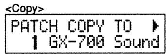
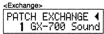
4 Use the NUMBER knob to select the copy destination (exchange destination) Patch number.
The effect sound will switch to that of the copy destination (exchange destination).
5 Press [WRITE] to execute the copy (exchange) operation. The copy destination (exchange destination) Patch number will be selected, and you will return to the Play page.
* To cancel the operation, press [PLAY] and you will return to the Play page.
Effect Sound Settings
- For the abbreviations used to indicate the names of effect devices, and for explanations of the parameters, refer to "Section 3 Effect Guide" (p.32).
Effect On/Off Settings
You can turn on whichever effects you wish to use, while effects you do not wish to use can be turned off. For effects which are turned on, the indicator of the effect select button corresponding to each effect will light.
(Procedure)
1 Press the effect select button that corresponds to the effect you wish to turn on or off.
The Play button indicator will go dark, and the screen will show the settings of the selected effect.
2 Once again, press the effect select button that corresponds to the effect you wish to switch. The effect will be turned on or off.
You can also switch the effect on/off by rotating/pressing the VALUE knob.
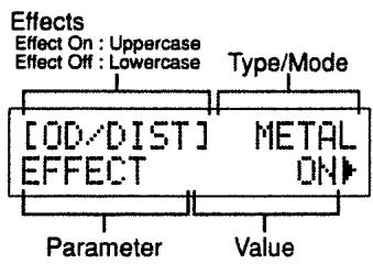
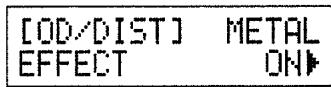
While you are making effect sound settings, the effect name will be displayed in uppercase characters for an effect which is turned on, and in lowercase characters for an effect which is turned off.
3 Repeat steps 1 - 2 to turn each effect on/off.
4 When you finish making settings:
- If you wish to continue setting other items, make the desired settings.
- If you wish to save the settings, use the Write operation (p.27).
Setting the Effect Unit Connection Order
You can freely set the order in which the effects are connected.
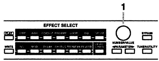
(Procedure)
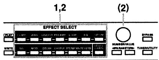
1 Press [LEVEL/CHAIN].
2 Use PARAMETER [][] to access the following parameter in the display (CHAIN).
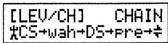
- Effects which are switched off will be shown in lowercase letters.
3 Use the VALUE knob to move the cursor (_A^) to the position where you wish to insert an effects processor.
4 Using the effect select buttons, select the effect you want. The selected effects processor will be inserted at the cursor's position.
5 Repeat steps 3 - 4 to place the effects in the desired order.
6 Press [PLAY] to complete the settings for the connection order you have produced. You are returned to the Play page. The display will indicate that editing is in progress, as shown below.
[NOTE]
While making settings for the connection order you can also switch effects on/off if you want. The two effects processors that appear immediately to left and right of the cursor (12) can be switched off or on by pressing their respective effect select button.
7 When you finish making settings:
- If you wish to continue setting other items, make the desired settings.
- If you wish to save the settings, use the Write operation (p.27).
Settings for Each Effects Processor
Each of the effects processors are controlled by a variety of parameters. By individually modifying the values for these parameters, you can create original effect sounds.
(Procedure)
1 Press the effect select button that corresponds to the effect you wish to edit.
The Play button indicator will go dark, and the screen will show the parameters of the selected effect.

2 Use PARAMETER [▲][▶] to access the parameter whose value you wish to modify.
If two or more parameters are displayed in a page, use PARAMETER [<] [▶] to move the cursor to the parameter that you wish to set.
- If you continue pressing the parameter button, the parameters will be displayed in succession.
- By holding down PARAMETER [←] ([▶]) and pressing PARAMETER [▶] ([←]), you can jump directly to important parameters. For effects with a small number of parameters, you can jump to the last (or first) parameter.
3 Rotate the VALUE knob to modify the value. By pressing the VALUE knob while you rotate it, you can make the value change faster.
* If the value consists of two choices, you can also switch between values by pressing the VALUE knob.
4 Repeat steps 2 - 3 to finish making effect settings.
5 As necessary, repeat from step 1 to change effects, and continue making settings.
6 When you finish making settings:
- If you wish to continue setting other items, make the desired settings.
- If you wish to save the settings, use the Write operation (p.27).
When the Play page appears in the display, functions (effects) that allow direct editing will be displayed.
Press PARAMETER [ ] to access the parameters of the displayed function (effect). Press PARAMETER [ ] to access the first parameter, and press PARAMETER [ ] to access the last parameter.
Level Meter
The parameters of each effect include a Meter function. When the Meter function is used, the output level of the specified effect will be indicated in the display, and a peak indicator will also operate, letting you check the output level of the effect. This conveniently allows you to check the output level of each effect.
- If the input level is too high, the GX-700 will not produce the desired effects.
(Procedure)
1 Press the effect select button that corresponds to the effect for which you want to display the meter.
The Play button indicator will go dark, and the display will show the parameters of the selected effect.
2 Use PARAMETER [][] to access the following parameter in the display.
<Effects With
an Independent Meter Function >
<Effects for which the Meter Function Is Included in the Output Level Adjustmen
3 When you finish checking
- You may wish to continue on and check other items, depending on your setup plans.
- If you wish to save the settings, perform the Write operation (p.27).
Effect Copy
This function copies parameter settings (in units of an individual effect) from another Patch number. It is convenient to use this function when you wish to use the same settings for a given effect in several Patch numbers.

(Procedure)
1 Press the effect select button that corresponds to the effect that you wish to effect copy.
The Play button indicator will go dark, and the parameters of the selected effect will appear in the display.
2 Use PARAMETER [][] to access the following parameter (EFFECT COPY).

3 Use the VALUE knob to select the copy source Patch number. At this time, the effects will switch to the copy source settings.
- To return to the settings being edited, select "EDIT."
4 When you finish making settings:
- If you wish to continue setting other items, make the desired settings.
- If you wish to save the settings, use the Write operation (p.27).
Modifying the Patch Name
Each Patch can have a name consisting of up to 12 characters. You can freely assign names to each Patch you create to remind yourself of the type of sound or the name of the song it is used for.
(Procedure)
1 Press [LEVEL/CHAIN].
2 Use PARAMETER [←][▶] to access the following parameter (NAME).
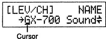
3 Use PARAMETER[<] [▶] to move the cursor to the character that you wish to modify.
4 Use the VALUE knob to modify the character.
- Pressing the VALUE knob switches you among uppercase characters, lowercase characters, numerals, and spaces.
5 Repeat steps 3 - 4 to assign the Patch name.
6 When you finish making settings:
- If you wish to continue setting other items, make the desired settings.
- If you wish to save the settings, use the Write operation (p.27).
Control Assign Settings
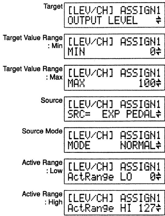
These settings allow you to control GX-700 parameters as you play, either from external MIDI devices or from pedals connected to the GX-700. For each Patch number, you can specify up to 4 parameters and the controller that will control each parameter.
Target: the parameter that will be controlled
Specify the parameter you wish to control. The following parameters can be selected as targets.

Output Level
Effect On/Off for each effect
Effect unit parameters
- BYPASS
TUNER
- Up to 4 Control Assign settings can be made for each Patch, but unused control assign targets must be set to "NOT ASSIGN."
- You may assign two or more controllers to control the same target, but in this case, avoid using two of these controllers to simultaneously modify the target parameter. This can produce noise.
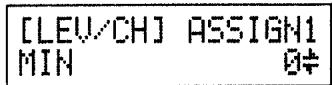
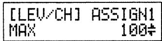
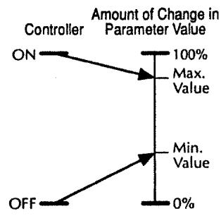
Target value range
Operations on the external device will modify the value of the target parameter within the range of the "minimum" and "maximum" values you specify.
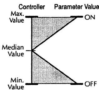
For on/off-type controllers such as foot switches, "Off" (CLOSE) will produce the "minimum value" and "On" (OPEN) will produce the "maximum value." For continuous controllers such as expression pedals, the value will change within the range of the specified "minimum" and "maximum." If the target is an on/off type parameter, it will be switched on or off by values above or below the central value of the controller.
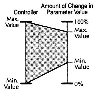
- The range available for setting will depend on the selected target.
- If you set the "minimum value" above the "maximum value," the direction of parameter change will be reversed.
- If after setting the "minimum" and "maximum" values you then change the target, the settings may change. After changing the target, check that the target value range has not changed.
Source: the controller that will control the parameter
Selection for the controller (source) that will control the target parameter.
The following controllers can be selected as sources.

- An expression pedal connected to the expression pedal jack (optional: EV-5 (Roland), FV-300L + PCS-33 (Roland))
- A foot switch (optional: FS-5U, FS-5L, FS-1(Roland), DP-2(Roland) etc.) connected to the Control 1/2 jack
- The expression pedal of an FC-200 MIDI Foot Controller (optional)
- The control pedal of an FC-200 MIDI Foot Controller (optional)
- Control Change messages (1 - 31, 64 - 95) from an external MIDI device
Source Mode: the result of operating a foot switch
This setting determines how the target parameter value will be affected when you operate a momentary-type foot switch (optional: FS-5U, DP-2 (Roland), etc.).
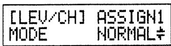
NORMAL: The parameter will normally be off (minimum value), and will be on (maximum value) only while the foot switch is depressed.
TOGGLE: The parameter will switch between off (minimum) and on (maximum) value each time you press the foot switch.
- If you have connected a latch-type foot switch (optional: FS-5L, FS-1(Roland), etc.) or if you have not selected a foot switch as the controller, this setting should be left at "NORMAL."
(Momentary-type and latch-type foot switches)
If you use a foot switch to switch Effect On/Off
You may use either a momentary-type or a latch-type foot switch. When using a momentary-type, select "TOGGLE." When using a latch-type, select "NORMAL." In either case, Effect On/Off will alternate each time you press the foot switch.
If you want an effect to become stronger while you depress a foot switch, or for the effect to be on only while the foot switch is depressed
Use a momentary-type foot switch, and select "NORMAL." In this case, the setting (on/off) will depend on whether the foot switch is depressed or not. This type of operation is not possible with a latch-type foot switch.
Active Range: Control Value Range
If a continuously variable controller such as an expression pedal or pitch lever has been selected as the control source, you can specify the range of values which will affect the target parameter. The value of the target parameter will not be affected by controller movements outside this specified range, but will remain at the "Maximum" or "Minimum" value.
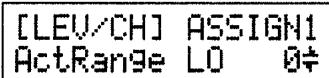
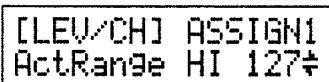
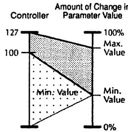
Example; Active Range Low:100, Active Range High:127

* If you are using an on/off control source such as a foot switch, leave this setting at "LO: 0", "HI: 127". Other settings may result in the value not changing.

(Procedure)
1 Press [LEVEL/CHAIN].
2 Use PARAMETER [←][▶] to access the following parameter (ASSIGN).
3 Use the VALUE knob to modify the setting.
4 Repeat steps 2-3 to make all desired control assign settings.
5 When you finish making settings:
- If you wish to continue setting other items, make the desired settings.
- If you wish to save the settings, use the Write operation (p.27).
Setting the Output Level
Here's how to adjust the GX-700's output level.
(Procedure)
1 Press [LEVEL/CHAIN].
2 Use PARAMETER [←][▶] to access the following parameter (LEVEL).

3 Use the VALUE knob to adjust the output level.
4 When you finish making settings:
- If you wish to continue setting other items, make the desired settings.
- If you wish to save the settings, use the Write operation (p.27).
Canceling Changes and Restoring Edited Data
To cancel changes ( edits) in an effect sound and return to the original values, use the following procedure. You can also bring back the edited data after editing has been canceled.
< Canceling Changes >
This function cancels editing of the effects, and restores the unmodified settings.
(Procedure)
1 While making changes, press [PLAY] to return to the Play page. The display will show a symbol indicating that the settings have been modified.
2 Rotate the NUMBER knob.
The Patch number will change, the modifications will be discarded, and the settings will return to their unmodified condition.
Even after canceling your edits, you can bring back the edited data and continue editing. Only the last-edited data can be brought back in this way.
(Procedure)
1 In the Play page, rotate the NUMBER knob.
The edited data for which editing was canceled is kept in the memory location immediately before Patch number "1."

2 Continue editing if desired (p.19).
Storing the Modified Settings (The Write Operation)
Patch settings you modify are temporary, and will return to the unmodified settings when you select another Patch. If you wish to keep the modified settings, use the Write operation.
(Procedure)
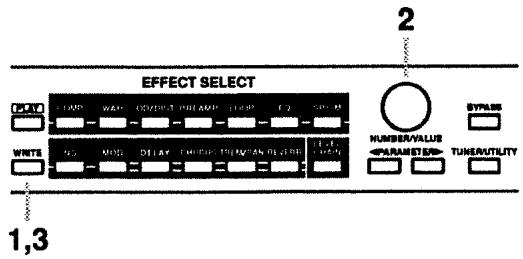
1 When you finish making settings, press [WRITE].
The following display will appear, and the effect sound will switch to the original effect sound that is currently stored in the Patch number.
PATCHWRITETO 1GX-700Sound
2 Use the VALUE knob to select the write-destination Patch number.
The effect sound will switch to the sound stored in the Patch number you select as the write-destination. This allows you to check whether or not the write-destination contains settings that you wish to avoid overwriting.
- If you wish to store the new settings in the original Patch number, this step is not necessary.
- Patch numbers 101 - 200 are the Preset area, and cannot be used to store your new Patches. If you have modified the settings of a Preset area Patch, you can store it in a User area (1 - 100) Patch number.
- To cancel the write operation and return to editing, press [PLAY].
3 Press [WRITE].
The modified settings will be stored in the Patch number you specified in step 2. When the Write operation is completed, the Play page will reappear.
While editing effect sound settings, you can use the Write operation to compare the current sound with the original un-edited sound or with another Patch number.
While making effect sound settings, press [WRITE] to enter Write mode so that the effect sound will switch to the un-edited effect sounds stored in each Patch number. You can rotate the NUMBER knob to switch Patch numbers (1 - 100).
If you wish to continue editing, press [PLAY] or the effect select button for the effect that you wish to edit. You will return to editing mode.
Utility Function Settings
The following pages explain the GX-700's Utility functions, which allow you to configure the unit for the setup you are using.
(Procedure)
1 Press [TUNER/UTILITY].
The Play button indicator will go dark, and the Tuner page will appear in the display.
2 Use PARAMETER [←] [▶] to access the parameter that you wish to edit.
- If you continue pressing a parameter button, the parameters will be displayed in succession.
- By holding down PARAMETER [←] ([▶]) and pressing PARAMETER [▶] ([←]), you can jump directly to important parameters.
3 Rotate the VALUE knob to modify the value. The value will change more rapidly if you press the VALUE knob as you rotate it.
* If the setting is a choice of two values, you can also switch between the two by pressing the VALUE knob.
4 Repeat steps 2 - 3 to set the desired Utility parameters.
5 Press [PLAY] or [TUNER/UTILITY] to end the procedure. (You will return to the Play page.)
- For details on
refer to "MIDI Utility Function Settings" (p.51). - For details on
refer to "Initializing the FC-200 from GX-700" (p.60). - For details on
refer to "Restoring the Factory Settings (Initialization)" (p.61).
Here you can make settings related to the tuner. The following parameters can be set. For details on these parameters, refer to "Tuner Settings" (p.15).
(TUNER PITCH) (435 - 445)
(TUNERSTRING DISPLAY) (OFF, ON, ON (b), ON (bb))
(TUNER LEVEL) (MUTE - 100)
< Function Setting >
(OUTPUT TYPE)
Specify the type of the equipment that is connected to the output jack.
OUTPUT TYPE GTR AMP(COMBO)
GUITAR AMP (COMBO):
Use this setting when connecting to the guitar input of a combo-type guitar amp (i.e., amp and speaker contained in a single unit).
GUITAR AMP (STACK):
Use this setting when connecting to the guitar input of a stack-type guitar amp (i.e., amp and speaker in separate units).
POWER AMP (COMBO):
Use this setting when connecting to the RETURN or MAIN IN of a combo-type guitar amp.
POWER AMP (STACK):
Use this setting when connecting to a power amp and speaker box, or to the RETURN or MAIN IN of a stack-type guitar amp.
LINE:
Use this setting when connecting to a mixer or MTR. This setting is also used when using headphones.
(SPEAKER SIMULATOR) (PATCH, ALWAYS ON, ALWAYS OFF)
Speaker SIMULATOR PATCH
This turns the Speaker Simulator On/Off. Normally, this setting is turned on/off in accord with the Patch settings, but you may wish to turn it on for all Patches when listening through headphones, or when carrying out line recording. Alternatively, when playing all Patches through an amp you may wish to turn it off.
PATCH:
The Speaker Simulator will be on or off as specified by each Patch.
ALWAYS ON:
The Speaker Simulator will be on regardless of the Patch setting.
- The parameter settings for the Speaker Simulator will be as specified in the Patch settings.
ALWAYS OFF:
The Speaker Simulator will be off regardless of the Patch setting.
(NS THRESHOLD LEVEL) (-20 dB - +20 dB)
NS THRESHOLD 0dB
Specify a compensatory adjustment of -20dB + 20dB to the threshold level of the noise suppressor that is included in each patch.
This allows you to make temporary compensation for the output level of the guitar you are using, without changing the settings of each patch.
- If you wish to use the settings of each patch without change, set this to "0 dB."
- This will have no effect on patches in which the noise suppressor is turned off.
(REVERB LEVEL) (0% - 200%)
REVERB LEVEL 100%
Specify a compensatory adjustment of 0% - 200% to the reverb level of each patch.
This allows you to make temporary compensation for the acoustics of the place where you are performing, without changing the settings of each patch.
- If you wish to use the settings of each patch without change, set this to "100%.
- This will have no effect on patches in which reverb is turned off.
(CONTROL 1/2 JACK)
(NUMBER UP, NUMBER DOWN, BYPASS, TUNER, ASSIGNABLE)
CONTROL 1 JACK NUMBER UP
CONTROL 2 JACK NUMBER DOWN
Set the function of the CONTROL 1/2 Jack.
NUMBER UP:
The jack will function as a remote jack for incrementing the Patch number. Connect a momentary-type foot switch (optional: FS-5U etc.)
NUMBERDOWN:
The jack will function as a remote jack for decrementing the Patch number. Connect a momentary-type foot switch (optional: FS-5U etc.)
TUNER:
The jack will function as a remote jack for turning the tuner on/off. Connect a momentary-type foot switch (optional: FS-5U etc.)
BYPASS:
The jack will function as a remote jack for turning bypass on/off. Connect a momentary-type foot switch (optional: FS-5U etc.)
ASSIGNABLE:
The jack will function as a controller jack for the Control Assign function. Connect the type of foot switch that is appropriate for the control target you select.
Connecting two foot switches (optional) and a PCS-31 connecting cable (optional)
Two control functions (Control 1 and Control 2) can be controlled by foot switch.
Connecting one foot switch
One control function (Control 1) can be controlled by foot switch.
(NUMBER UP/DOWN) (1 - 200)

Specify the range of Patch numbers that can be selected by a foot switch connected to the CONTROL 1/2 Jack. Specify the range by a lower limit "MIN" and an upper limit "MAX."
(ASSIGN HOLD) (ON, OFF)

Specifies whether or not the previous values of controller sources will be maintained when the Patch changes.
ON: Controller source values will be maintained when the Patch changes. When you select a new Patch number, target parameters which are using the same sources will maintain the previous values of the controller sources.
OFF: Controller source values will not be maintained when the Patch changes. When you select a new Patch number, the effect sound will initially be unaffected by the current position of the controllers. As soon as you move a controller and its data is transmitted to the GX-700, the target parameter for that controller will be affected.
(BYPASS MODE) (BYPASS, MUTE)
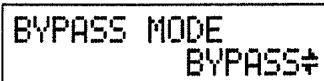
Specify the result of turning BYPASS On.
BYPASS: The guitar sound being input will be output without change.
MUTE: Nothing will be output from any OUTPUT Jack; i.e., the GX-700 will be muted (silent).
(LCD CONTRAST) (0 - 15)
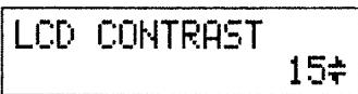
Depending on the location where you place the GX-700, the display may be difficult to read. In this case, adjust the display contrast.
< MIDI-Related Settings >
This section contains the MIDI-related settings. The following parameters can be set. For details on each parameter, refer to "MIDI Utility Function Settings" (p.51).
(MIDI CHANNEL) 1-16
(MIDI OMNI MODE) OMNI OFF, OMNI ON
(MIDI DEVICE ID) 1-32
(MIDI PROGRAM MAP)
(MIDI BULK DUMP)
(MIDI BULK LOAD)
This sets the FC-200 to the optimal settings for use when connected to the GX-700. The following parameters can be set. For details on connections etc., refer to "Initializing the FC-200 from GX-700" (p.60).
(FC-200 INITIALIZE)
(Initialization) >
This procedure returns (initializes) the GX-700's settings to their factory-default values. For more information, check out "Restoring the Factory Settings (Initialization)" (p.61).
(GX-700 INITIALIZE)
Section
3
Effect Guide
This section explains each effect and the function of the parameters which make up each effect.
* The sound being input to each effect is called the "direct sound," and the sound modified by the effect is called the "effect sound."
COMPRESSOR
EFFECT
OFF, ON
MODE
COMPRESSOR, LIMITER
< COMPRESSOR >
SUSTAIN
0
100
ATTACK
0
100
TONE -50
+50
LEVEL
0
100
< LIMITER >
THRESHOLD
0
100
RELEASE
0
100
TONE
-50
+50
LEVEL
0
100
The compressor is an effect that attenuates loud input levels and boosts soft input levels, thus evening out the volume to create sustain without distortion.
The limiter attenuates loud input levels to prevent distortion.
EFFECT
Turns the compressor/limiter effect on/off.
MODE
Select either Compressor or Limiter.
COMPRESSOR: The effect will function as a compressor.
LIMITER:
The effect will function as a limiter.
< When "COMPRESSOR" is selected >
SUSTAIN
Adjusts the range (time) over which low-level signals are boosted. Larger values will result in longer sustain.
ATTACK
Adjusts the strength of the picking attack. Larger values will result in a sharper attack, creating a more clearly defined sound.
TONE
Adjusts the tone.
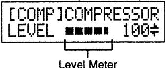
LEVEL
Adjusts the volume. At the same time, the output level of the compressor is indicated by a meter in the display.
< When "LIMITER" is selected >
THRESHOLD
Adjust this as appropriate for the input signal from your guitar. When the input signal level exceeds this threshold level, limiting will be applied.
RELEASE
This adjusts the time from when the signal level drops below the threshold until when limiting is removed.
TONE
Adjusts the tone.
LEVEL
Adjusts the volume. At the same time, the output level of the limiter is indicated by a meter in the display.
WAH
EFFECT OFF, ON MODE PEDAL WAH, SW-PEDAL WAH, AUTO WAH < PEDAL WAH, SW-PEDAL WAH > FREQUENCY 0 100 PEAK 0 100 PEDAL FIXED, EXP PEDAL, FC-200EXP, MIDI C#1-31, 64-95 PEDAL MINIMUM 0 100 PEDAL MAXIMUM 0 100 LEVEL 0 100 < AUTO WAH > POLARITY DOWN, UP SENSITIVITY 0 100 MANUAL 0 100 PEAK 0 100 RATE 0 100 DEPTH 0 100 LEVEL 0 100
The Wah effect creates a unique tone by changing the frequency response characteristics of a filter. Pedal Wah lets you use an expression pedal or the like to obtain realtime control of the wah effect. Auto Wah creates an automatic wah by cyclically changing the filter, or by changing the filter in response to the volume of the input.
EFFECT
Turns the pedal wah/auto wah effect on/off.
MODE
Selects either pedal wah or auto wah.
PEDAL WAH:
The effect will function as a pedal wah.
SW-PEDAL WAH:
This is a pedal wah that can be switched on/off by pressing the pedal.
AUTO WAH:
The effect will function as an auto wah.
< When "PEDAL WAH" or "SW-PEDAL WAH" Is Selected >
FREQUENCY
Adjusts the center frequency at which the wah effect will be applied.
PEAK
Adjusts the way in which the wah effect applies to the area around the center frequency. Lower values will produce a wah effect over a wide area around the center frequency. Higher values will produce a wah effect in a narrow area around the center frequency.
* With a value of "50" a standard wah sound will be produced.
PEDAL
Specify the expression pedal (MIDI message) that will operate the wah pedal.
FIXED:
Use this setting when you want a fixed wah effect. The wah effect will be provided at the fixed frequency specified by the "FREQUENCY" setting.
EXP PEDAL:
Use an expression pedal (optional: FV-300L + PCS-33 (Roland), EV-5 (Roland)) connected to the EXP PEDAL jack.
FC-200EXP:
The expression pedal of the FC-200 will be used.
MIDI C#1-31, 64-95:
MIDI control change messages will be used. Specify the controller number.
PEDAL MINIMUM
Specify the lower limit of the "FREQUENCY" sweep controlled by the pedal.
The "FREQUENCY" will be swept through the range between the "PEDAL MINIMUM" and the "PEDAL MAXIMUM" to create the wah pedal effect.
PEDAL MAXIMUM
Determines the upper limit of the "FREQUENCY" sweep controlled by the pedal.
LEVEL
Adjusts the volume. At the same time, the output level of the wah pedal will be indicated by a meter in the display.
< When "AUTO WAH" is selected >
POLARITY
Selection for the direction in which the filter will change in response to the input.
UP: The frequency of the filter will rise.
DOWN: The frequency of the filter will fall.
SENSITIVITY
This adjusts the sensitivity at which the filter will change in the direction determined by the Polarity setting. Higher values will result in a stronger response. With a setting of "0," the strength of picking will have no effect.
MANUAL
Adjusts the center frequency at which the wah effect will be applied.
PEAK
Adjusts the way in which the wah effect applies to the area around the center frequency. Lower values will produce a wah effect over a wide area around the center frequency. Higher values will produce a wah effect in a narrow area around the center frequency.
* With a value of "50" a standard wah sound will be produced.
RATE
Adjusts the frequency of the auto wah.
DEPTH
Adjusts the depth of the auto wah effect.
LEVEL
Adjusts the volume. At the same time, the output level of the auto wah will be indicated by a meter in the display.
OVERDRIVE / DISTORTION
EFFECT OFF, ON TYPE VINTAGE OD, TURBO OD, BLUES, DISTORTION, TURBODISTORTION, METAL, FUZZ DRIVE 0 100 BASS -50 +50 TREBLE -50 +50 LEVEL 0 100
These effects are used for distorting sounds and creating a long sustain.
EFFECT
Turns the overdrive/distortion effect on/off.
TYPE
Selects the type of distortion.
VINTAGE OD:
Allows you to obtain a soft overdrive that sounds just like what is produced by vacuum tube distortion.
TURBO OD:
Allows you to obtain a rich effect just like distortion, without losing the subtle nuance of the overdrive.
BLUES:
This creates an overdrive with crunchy distortion. The processed distortion can faithfully reproduce the tone changes created by picking nuances, or controlling the knobs on the guitar.
DISTORTION:
This produces a standard distortion.
TURBO DISTORTION:
A distortion sound with special emphasis in the mid- and low-range, as when a large amp is played at high volume.
METAL:
This produces a rich and powerful heavy metal sound.
FUZZ:
This produces a basic fuzz sound with.
DRIVE
Adjusts the depth of distortion.
BASS
Adjusts the tone for the low frequency range.
TREBLE
Adjusts the tone for the high frequency range.
LEVEL
Adjusts the volume. At the same time, the output level of the overdrive/distortion will be indicated by a meter in the display.
PREAMP
EFFECT OFF, ON TYPE JC-120, CLEAN TWIN, MATCH DRIVE, BG LEAD, MS1959(I), MS1959(II), MS1959(I+II),SLDNLEAD,METAL5150 VOLUME 0 100 BASS 0 100 MIDDLE 0 100 TREBLE 0 100 PRESENCE 0 100 MASTER 0 100 BRIGHT OFF, ON GAIN LOW, MIDDLE, HIGH
Use the preamp to adjust the distortion and tone color of the guitar.
EFFECT
Turns the preamp effect on/off.
TYPE
Selects the type of guitar preamp. The characteristics of various guitar amps have been analyzed, and their distortion and tone color have been simulated by these settings.
JC-120:
The sound of the Roland "JC-120" (Jazz Chorus 120), a favorite of pro musicians around the world.
CLEAN TWIN:
The sound of a conventional built-in tube amp.
MATCH DRIVE:
A simulation of the latest tube amp widely used in styles from blues and rock.
BG LEAD:
The sound of a tube amp typical of the late '70s to '80s, characterized by a distinctive mid-range.
MS1959 (I, II, I+II):
The sound of a large tube amp stack that was indispensable to the British hard rock of the '70s, and is used to this day by many hard rock guitarists.
I: A trebly sound created by using input I of the guitar amp.
II: A mild sound created by using input II of the guitar amp.
I+II: The sound of connecting inputs I and II of the guitar amp in parallel, creating a sound with a stronger low end than I.
SLDN LEAD:
A tube amp sound with versatile distortion, usable in a wide range of styles.
METAL 5150:
The sound of a large tube amp, suitable for heavy metal.
VOLUME
Adjusts the volume and distortion of the amp.
BASS
Adjusts the tone for the low frequency range.
MIDDLE
Adjusts the tone for the middle frequency range.
* If you have selected "MATCH DRIVE" as the type, the middle control will have no effect.
TREBLE
Adjusts the tone for the high frequency range.
PRESENCE
Adjusts the tone for the ultra high frequency range.
- If you have selected "MATCH DRIVE" as the type, raising presence will cut the high range (the value will change from "0" to "-100").
MASTER
Adjusts the volume of the entire preamp. At the same time, the output level of the preamp will be indicated by a meter in the display.
BRIGHT
Turns the bright setting on/off.
ON: Bright is switched on to create a lighter and crisp tone.
OFF: Bright is not used.
- Depending on the "TYPE" setting, this may not be displayed.
GAIN
Adjusts the distortion of the amp. Distortion will successively increase for settings of "LOW," "MIDDLE" and "HIGH."
LOOP
EFFECT OFF, ON RETURN LEVEL 0 100 % SEND LEVEL 0 100 % MODE SERIES, PARALLEL
Make settings for an external effects processor connected to the loop send/loop return jacks.
EFFECT
Turns the loop on/off.
RETURN LEVEL
Adjusts the input level of the RETURN jack. At the same time, the return level will be indicated by a meter in the display.
SEND LEVEL
Adjusts the output level of the SEND jack.
MODE
Set the function of the SEND/RETURN jacks.
SERIES: The loop will be connected in series with the internal effects.

PARALLEL: The loop will be connected in parallel with the internal effects.

3BAND EQUALIZER
EFFECT OFF, ON LOW GAIN -20 +20 dB MIDDLE FREQUENCY 100Hz 10.0kHz MIDDLE GAIN -20 +20 dB MIDDLE Q 0.5 16 HIGH GAIN -20 +20 dB LEVEL -20 +20 dB
Use a three-band equalizer to adjust the tone of each frequency band.
EFFECT
Switches the three-band equalizer effect on/off.
LOW GAIN
Adjusts the gain (amount of boost/cut) for the low range.
MIDDLE FREQUENCY
Adjusts the center frequency that the middle range adjustment will affect.
MIDDLE GAIN
Adjusts the gain (amount of boost/cut) for the middle range.
MIDDLE Q
Adjusts the width of the area centered at the "MIDDLE FREQUENCY" that the equalizer will affect.
HIGH GAIN
Adjusts the gain (amount of boost/cut) for the high range.
LEVEL
Adjusts the volume after the equalizer. At the same time, the output level of the equalizer will be indicated by a meter in the display.
SPEAKER SIMULATOR
EFFECT
OFF, ON
TYPE
SMALL, MIDDLE, JC-120, BUILT IN 1-4, BG STACK 1-2, MS STACK1-2, METAL STACK
MIC SETTING
1 10
MIC LEVEL
100
DIRECT LEVEL
100
OUTPUT METER
This simulates the characteristics of various types of speakers. When the output of the GX-700 is connected directly to a mixer, etc., this can be used to create the sound of your favorite speaker system.
EFFECT
Turns the speaker simulator on/off.
* If the Utility setting "SPEAKER SIMULATOR" (p.29) is set to "ALWAYS ON" or "ALWAYS OFF," the display will be as follows, and the effect sound will not change even if this parameter is switched on or off.


TYPE
Selects the type of speaker that will be simulated.
SP Simulator Type Cabinet Speaker Unit Microphone Setting Comments SMALL Small open-back enclosure 10 inch On Mic MIDDLE Open-back enclosure 12 inch On Mic JC-120 Open-back enclosure 12 inch (two units) On Mic JC-120 Simulation BUILT IN 1 Open-back enclosure 12 inch (two units) On Mic A setting suitable for Clean Twin BUILT IN 2 Open-back enclosure 12 inch (two units) Off Mic A setting suitable for Clean Twin BUILT IN 3 Open-back enclosure 12 inch (two units) On Mic A setting suitable for Match Drive BUILT IN 4 Open-back enclosure 12 inch (two units) Off Mic A setting suitable for Match Drive BG STACK 1 Large Sealed enclosure 12 inch (two units) On Mic A setting suitable for BG Lead BG STACK 2 Large sealed enclosure 12 inch (two units) Off Mic A setting suitable for BG Lead MS STACK 1 Large sealed enclosure 12 inch (four units) On Mic A setting suitable for MS1959 MS STACK 2 Large sealed enclosure 12 inch (four units) Off Mic A setting suitable for MS1959 METAL STACK Large dual stack 12 inch (four units) Off Mic
* "On Mic" simulates the sound when a dynamic microphone is used, and "Off Mic" simulates the sound when a condenser microphone is used.
Best Match
[PREAMP] Type [SP Simulator] Type JC-120 JC-120 CLEAN TWIN BUILT IN 1, BUILT IN 2, MIDDLE MATCH DRIVE BUILT IN 3, BUILT IN 4 BG LEAD BG STACK 1, BG STACK 2, MIDDLE MS1959 (1) MS STACK 1, MS STACK 2, METAL STACK MS1959 (2) MS STACK 1, MS STACK 2, METAL STACK MS1959 (1+2) MS STACK 1, MS STACK 2, METAL STACK SLDN LEAD MS STACK 1, MS STACK 2, METAL STACK METAL 5150 MS STACK 1, MS STACK 2, METAL STACK
MIC SETTING
Simulates the location of the microphone placement. A setting of "1" places the microphone in the center of the speaker cone, and "2" and "3" place the microphone progressively further away.
MIC LEVEL
Adjusts the volume of the microphone.
DIRECT LEVEL
Adjusts the volume of the direct sound.
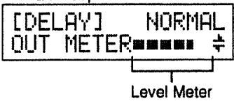
OUTPUT METER
The output level of the speaker simulator will be indicated by a meter in the display.
NOISE SUPPRESSOR
EFFECT OFF, ON THRESHOLD 0 100 RELEASE 0 100 DETECT GUITAR IN, NS IN LEVEL 0 100
This effect reduces the noise and hum picked up by guitar pickups. Since it suppresses the noise in synchronization with the envelope of the guitar sound (the way in which the guitar sound decays over time), it has very little effect on the guitar sound, and does not harm the natural character of the sound.
EFFECT
Turns the noise suppressor effect on/off.
THRESHOLD
Adjust this parameter as appropriate for the volume of the noise. If the noise level is high, a higher setting is appropriate. If the noise level is low, a lower setting is appropriate. Adjust this value until the decay of the guitar sound is as natural as possible.
* High settings for the Threshold parameter may result in there being no sound when you play with your guitar volume turned down.
RELEASE
Adjusts the time from when the noise suppressor begins to function until the volume reaches "0".
DETECT
Specify the point where the noise suppressor detects the envelope.
GUITAR IN:
The envelope of the input level at the INPUT Jack will be used.
NS IN:
The envelope of the input level to the noise suppressor will be used.
- Normally you will set this at "GUITAR IN."
* If reverberation-type effects such as delay or reverb are connected before the noise suppressor, set this to "NS IN" to prevent the reverberation from being cut off unnaturally.
LEVEL
Adjusts the volume. At the same time, the output level of the noise suppressor will be indicated by a meter in the display.
MODULATION
EFFECT OFF, ON MODE FLANGER, PHASER, PITCH SHIFTER, HARMONIST, VIBRATO, RING MODULATOR, HUMANIZER < FLANGER > RATE 0 100 DEPTH 0 100 MANUAL 0 100 RESONANCE -100 +100 SEPARATION -100 +100 GATE OFF, 1 to 100 OUTPUT METER < PHASER > TYPE 4STAGE, 6STAGE, 8STAGE, 10STAGE, 12STAGE RATE 0 100 DEPTH 0 100 MANUAL 0 100 RESONANCE -100 +100 STEP OFF, 1 to 100 OUTPUT METER < PITCH SHIFTER > TYPE SLOW, FAST, MONO VOICE [1-3] PITCH [1-3] -24 +24 FINE [1-3] -50 +50 PAN [1-3] L100:OR L0:100R LEVEL [1-3] 0 100 BALANCE D100:OE D0:100E TOTAL LEVEL 0 100 OUTPUT METER < HARMONIST > KEY Cmaj G#min VOICE [1-3] INTERVAL [1-3] #Oct #Oct PAN [1-3] L100:OR L0:100R LEVEL [1-3] 0 100 BALANCE D100:OE D0:100E TOTAL LEVEL 0 100 OUTPUT METER IN C B *User Scale OUT [1-3] #Oct #Oct *User Scale < VIBRATO > TRIGGER OFF, ON, AUTO RISE TIME 0 100 RATE 0 100 DEPTH 0 100 OUTPUT METER < RING MODULATOR > FREQUENCY INTELLIGENT, 1 to 100 EFFECT LEVEL 0 100 DIRECT LEVEL 0 100 OUTPUT METER
COMP WAH OD/DIST PREAMP LOOP EQ SPSIM NS MOD DELAY CHORUS TREM/PAN REVERB
TYPE AUTO, PEDAL
VOWEL1 a,e,i,o,u
VOWEL2 a,e,i,o,u
RATE 0 100 \*TYPE:AUTO
DEPTH 0 100 \*TYPE:AUTO
TRIGGER OFF, AUTO \*TYPE:AUTO
PEDAL EXP PEDAL,FC-200EXP
MIDI C#1-31, 64-95 *TYPE:PEDAL
OUTPUT METER
This produces one of the following effects: flanger, phaser, pitch shifter, harmonist, vibrato, ring modulator, or humanizer.
EFFECT
Turns the modulation effect on/off.
MODE
Selects either flanger, phaser, pitch shifter, harmonist, vibrato, ring modulator, or humanizer.
FLANGER:
The flanging effect gives a twisting, jet-airplane-like character to the sound.
PHASER:
By adding varied-phase portions to the direct sound, the phaser effect gives a whooshing, swirling character to the sound.
PITCH SHIFTER:
This creates an effect sound at a different pitch. The pitch can be shifted by up to 2 octaves, and you may play chords on your guitar.
HARMONIST:
This creates harmony in the key (scale) that you are using. When using the harmonist effect, play only single notes on your guitar.
VIBRATO:
This effect creates vibrato by slightly modulating the pitch.
RING MODULATOR:
This creates a bell-like sound by ring-modulating the guitar sound with the signal from the internal oscillator. The sound will be unmusical and lack distinctive pitches.
HUMANIZER:
This creates a human-like voice sound from the guitar sound.
< When "FLANGER" is selected >
RATE
This sets the rate of the flanging effect.
DEPTH
Determines the depth of the flanging effect.
MANUAL
Adjusts the center frequency at which to apply the effect.
RESONANCE
Determines the amount of resonance (feedback). Increasing the value will emphasize the effect, creating a more unusual sound. Setting it to a minus value will create resonance having a reversed phase.
SEPARATION
Adjusts the diffusion. The Diffusion increases as the value increases.
GATE
This can be effectively used to cyclically cut the output from the flanger. Increasing the value will shorten the interval.
OUTPUT METER
The output level of the flanger will be indicated by a meter in the display.
< When "PHASER" Is Selected >
TYPE
Selects the number of stages that the phaser effect will use.
4 STAGE: This is a four-phase effect. A light phaser effect is obtained.
6 STAGE: This is a six-phase effect.
8 STAGE: This is an eight-phase effect. It is the most popular phaser effect.
10 STAGE: This is a ten-phase effect.
12 STAGE: This is a twelve-phase effect. A deep phase effect is obtained.
RATE
This sets the rate of the Phaser effect.
DEPTH
Determines the depth of the Phaser effect.
MANUAL
Adjusts the center frequency of the phaser effect.
RESONANCE
Determines the amount of resonance (feedback). Increasing the value will emphasize the effect, creating a more unusual sound. Setting it to a minus value will create resonance having a reversed phase.
STEP
This can be used to cause the sound to change in a stepped manner. Increasing the value will make the change finer.
OUTPUT METER
The output level of the phaser will be indicated by a meter in the display.
< When "PITCH SHIFTER" Is Selected >
TYPE
Selection for the type of pitch shifter.
SLOW:
Chords may be played. The response is slower, but the sound will waver less than "FAST."
FAST:
Chords may be played. The response is quicker than "SLOW."
MONO:
This is for mono input. Compared to conventional pitch shifters, the sound does not waver.
VOICE

Specify the number of voices for the pitch shifter. Up to 3 notes can be output simultaneously.
PITCH
The pitch shifted notes, specifies the pitch difference in semitone steps.
FINE
The pitch shifted notes, allows a fine adjustment of the pitch.
* If you were to shift the value of this parameter through its entire range (starting at -50 and finishing at +50) you would realize a total change of one semitone in the pitch.
PAN
Adjusts the stereo position (pan) for each shifted sound.
LEVEL
The pitch shifted notes, adjusts the output level.
BALANCE
Adjusts the output balance between the direct sound (D) and the overall effect sound (E).
TOTAL LEVEL
Adjusts the volume of the entire pitch shifter.
OUTPUT METER
The output level of the pitch shifter will be indicated by a meter in the display.
< When "HARMONIST" Is Selected >
KEY
This sets the key for the song. If you make the appropriate key setting, the harmony that is generated will be appropriate for the song.
The key of the song will be as follows depending on the number of symbols (\# ,) appearing in the staff.


COMP WAH OD/DIST PREAMP LOOP EQ SPSIM NS MOD DELAY CHORUS TREM/PAN REVERB
VOICE
Specify the number of voices for the harmonist. Up to 3 notes can be output simultaneously.
INTERVAL
Determines the pitch interval (relative to the input note) at which the harmony will be generated. You can specify an interval of up to ± 2 octaves relative to the input note.
The display will be as follows.

* If the resulting harmony is not what you want, you can make settings for "IN" (input note) and "OUT" (output note) and switch to the user scale. If you select the user scale, this parameter will be displayed as "USER." For details refer to "About the User Scale".
PAN
Adjusts the stereo position (pan) for each pitch shifted notes.
LEVEL
For each of the harmony notes, adjust the output level.
BALANCE
Adjusts the output balance between the direct sound (D) and the overall effect sound (E).
TOTAL LEVEL
Adjusts the volume of the entire harmonist.
OUTPUT METER
The output level of the harmonist will be indicated by a meter in the display.
IN
This displays the note name of the input note of the user scale.
OUT
This displays the note name of the output note of the user scale. User scale settings are made by specifying the "OUT" notes that will be output for each "IN" note.
- About the User Scale
If the resulting harmony is not what you want, you can output harmony using the user scale you specify here. You can make separate user scale settings for each Patch number and for each voice.
On the GX-700, make user scale settings as follows.
(Procedure)
1 While editing harmonist parameters, use PARAMETER [][] to access the following parameter in the display.

2 Use PARAMETER [←][▶] to move the cursor to "IN." Play a single note on your guitar, and the GX-700 will detect the pitch and display it as the input note name.
You can also use the VALUE knob to display the input note name.
3 Use PARAMETER [][] to move the cursor to "OUT." Play a single note on your guitar, and the GX-700 will detect the pitch and display it as the output note name.
You can also use the VALUE knob to display the output note name.
4 Repeat steps 2 - 3 to specify the output note for each input note.
* Make settings for each voice that requires a user scale.
5 Return to the normal editing procedure.
* When the user scale is used, the "INTERVAL" parameter will indicate "USER."
* To cancel the user scale and return to the original scale, rotate the VALUE knob for the "INTERVAL" parameter to re-specify (for each voice) the pitch interval that will be added to the input note.
< When "VIBRATO" Is Selected >
TRIGGER
Use a foot switch to turn the vibrato on/off. When "AUTO" is selected, vibrato will automatically be applied each time picking occurs.
- This effect is designed to produce vibrato only while you depress a foot switch to produce a trigger signal.
RISE TIME
Adjusts the time from when the trigger is turned On until the specified vibrato depth is reached.
RATE
Adjusts the frequency of the vibrato.
DEPTH
Adjusts the depth of the vibrato.
OUTPUT METER
The output level of the vibrato will be indicated by a meter in the display.
FREQUENCY
Adjust the frequency of the internal oscillator. If "INTELLIGENT" is selected, the oscillator frequency will change according to the pitch of the input sound, producing a sound that retains a sense of pitch.
* If "INTELLIGENT" is used, the desired effect will not be obtained unless the pitch of the guitar is detected correctly. We recommend that you use this for playing single notes.
EFFECT LEVEL
Adjusts the volume of the effect sound.
DIRECT LEVEL
Adjusts the volume of the direct sound.
OUTPUT METER
The output level of the ring modulator will be indicated by a meter in the display.
< When "HUMANIZER" Is Selected >
TYPE
Select the way in which the two vowels will be switched.
AUTO:
Adjust "RATE" and "DEPTH" to switch between the two vowels.
PEDAL:
Use a pedal to switch between the two vowels.
VOWEL1
This selects the first vowel.

VOWEL2
This selects the second vowel.
RATE
Adjusts the cycle for switching between the two vowels.
DEPTH
Adjusts the depth of the effect.
TRIGGER
This selects whether or not to have the timing adjusted so the unit will always begin with "VOWEL1" when you play string.
AUTO: Yes, adjust the timing.
OFF: No, do not adjust the timing.
COMP WAH OD/DIST PREAMP LOOP EQ SPSIM NS MOD DELAY CHORUS TREM/PAN REVERB
PEDAL
Specify the expression pedal (MIDI message) that will operate the humanizer.
EXP PEDAL:
Use an expression pedal (optional: FV-300L + PCS-33 (Roland), EV-5 (Roland)) connected to the EXP PEDAL jack.
FC-200EXP:
The expression pedal of the FC-200 will be used.
MIDIC#1-31,64-95:
MIDI control change messages will be used. Specify the controller number.
OUTPUT METER
The output level of the humanizer will be indicated by a meter in the display.
DELAY
EFFECT OFF, ON MODE NORMAL, TEMPO < NORMAL > DELAY TIME C 1 2000 msec DELAY TIME L 1 400 % DELAY TIME R 1 400 % FEEDBACK 0 100 LEVEL C 0 100 LEVEL L 0 100 LEVEL R 0 100 HIGH DAMP -50 0 HIGH CUT FILTER 500 Hz to 12.5kHz, FLAT SMOOTH OFF, ON EFFECT LEVEL 0 100 DIRECT LEVEL 0 100 OUTPUT METER < TEMPO > TEMPO IN FIXED, CONTROL 1-2, FC-200CTL,
MIDI C#1-31, 64-95 TEMPO 50 300 *TEMPoin:FIXED DELAY INTERVAL C 1/4 4.0 DELAY INTERVAL L 1 400 % DELAY INTERVAL R 1 400 % FEEDBACK 0 100 LEVEL C 0 100 LEVEL L 0 100 LEVEL R 0 100 HIGH DAMP -50 0 HIGH CUT FILTER 500 to 12.5kHz, FLAT SMOOTH OFF, ON EFFECT LEVEL 0 100 DIRECT LEVEL 0 100 OUTPUT METER
This effect adds delayed sound to the direct sound, giving more body to the sound or creating special effects.

EFFECT
Turns the delay effect on/off.
MODE
Specify the delay mode.
NORMAL:
A conventional delay.
TEMPO:
A delay that lets you set the delay time using a foot switch.
< When "NORMAL" Is Selected >
DELAY TIME C
Adjusts the delay time of the center channel.
DELAY TIME L
Adjusts the delay time of the left channel delay. This setting adjusts the left channel delay time relative to the center channel delay time (considered as 100% ).
DELAY TIME R
Adjusts the delay time of the right channel delay. This setting adjusts the right channel delay time relative to the center channel delay time (considered as 100% ).
FEEDBACK
Feedback refers to returning the delayed signal back into the input of the delay. This parameter adjusts the volume that is returned to the input. Higher settings will result in more delay repeats.
LEVEL C
Adjusts the volume of the center channel delay.
LEVEL L
Adjusts the volume of the left channel delay.
LEVEL R
Adjusts the volume of the right channel delay.
< When "TEMPO" Is Selected >
TEMPO IN
Determines the foot switch that will set the basic tempo.
FIXED:
The basic tempo will not be used. Instead, the delay times will be determined by the settings of "TEMPO" (song tempo) and "INTERVAL."
CONTROL 1, 2:
A foot switch (optional: FS-5U, etc.) connected to the Control 1/2 jack will be used.
* Set the function of the Control 1/2 jack (p.29) to "ASSIGN-ABLE."
FC-200CTL:
The control pedal of the FC-200 will be used.
MIDI C#1-31, 64-95:
MIDI control change messages will be used. Specify the controller number here.
TEMPO
When "TEMPO IN" is set to "FIXED," this sets the tempo.
* This parameter is displayed only if "TEMPORIN" is set to "FIXED."
DELAY INTERVAL C
Adjusts the delay time of the center channel. The delay time is calculated relative to the basic tempo (the intervals at which you press the foot switch), which is considered as "1."
* For details on tempo delay, refer to "What is Tempo Delay" (p.46).
DELAY INTERVAL L
Adjusts the delay time of the left channel delay. This setting adjusts the left channel delay time relative to the center channel delay time (considered as 100% ).
DELAY INTERVAL R
Adjusts the delay time of the right channel delay. This setting adjusts the right channel delay time relative to the center channel delay time (considered as 100% ).
FEEDBACK
Feedback refers to returning the delayed signal back into the input of the delay. This parameter adjusts the volume that is returned to the input. Higher settings will result in more delay repeats.
COMP WAH OD/DIST PREAMP LOOP EQ SPSIM NS MOD DELAY CHORUS TREM/PAN REVERB
LEVEL C
Adjusts the volume of the center channel delay.
LEVEL L
Adjusts the volume of the left channel delay.
LEVEL R
Adjusts the volume of the right channel delay.
< Parameters Common to All Modes >
HIGH DAMP
Adjusts the amount of high damping (the way in which the higher frequency range of the delay sound will diminish). With a setting of "0" there will be no high damping effect.
HIGH CUT FILTER
The high cut filter cuts the frequencies below the specified frequency. This setting adjusts the frequency at which the high cut filter will begin to take effect. When "FLAT" is selected, the high cut filter will have no effect.
SMOOTH
If smooth is turned on, the delay time will change smoothly when the delay time is modified.
EFFECT LEVEL
Adjusts the overall volume of the entire delay sound.
DIRECT LEVEL
Adjusts the volume of the direct sound.
OUTPUT METER
The output level of the delay is indicated by a meter in the display.
What is Tempo Delay
Tempo Delay allows you to set the delay to a desired tempo simply by tapping on a foot switch in time to the song you are playing.
(Procedure)
1 While editing delay settings, use PARAMETER [][] to access the following parameter (MODE), and use the VALUE knob to select the "TEMPO."

2 Use PARAMETER [▶][▶] to access the following parameter (DELAY INTERVAL [C]), and use the VALUE knob to set the interval.

This setting determines the spacing of the delay relative to the time between presses of the foot switch (basic tempo: the length of a quarter note) which is considered as "1."
The time between presses of the foot switch and the interval setting work together to determine the delay time as follows.

3 Use PARAMETER [][] to access the following parameter (TEMPO IN), and use the VALUE knob to select the foot switch to input the basic tempo.

4 Return to normal editing.
For a Patch that uses tempo delay, pressing the foot switch three or more times at regular intervals in synchronization with the tempo of the song will determine the basic tempo. This basic tempo together with the interval setting determine the delay time.
* The basic tempo is automatically set to = 120 each time the GX-700 is switch on.
* Once established, the basic tempo will be remembered until you operate the foot switch to set a new basic tempo, or until the power is turned off.
* Delay time can be set to a maximum of 2.0 seconds. If the basic tempo and the interval setting would specify a delay time of greater than 2.0 seconds, the actual delay time will be 2.0 seconds.
CHORUS
EFFECT OFF, ON MODE MONO, STEREO RATE 0 100 DEPTH 0 100 PRE DELAY 0 50.0 msec LOW CUT FILTER FLAT, 55 to 800Hz HIGH CUT FILTER 500Hz to 12.5kHz, FLAT LFO WAVE TRI10:0SIN TRI0:10SIN EFFECT LEVEL 0 100 OUTPUT METER
In this effect, a slightly detuned sound is added to the original sound to add depth and breadth.
EFFECT
Turns the chorus effect on/off.
MODE
Selection for the chorus mode.
MONO: This chorus effect outputs the same sound from both L and R.
STEREO: This is a stereo chorus effect that adds different chorus sounds to L and R.
RATE
Adjusts the rate of the Chorus effect.
DEPTH
Adjusts the depth of the Chorus effect. To use it for doubling, set the value to "0."
PRE DELAY
Adjusts the time needed for the effect sound to be output after the direct sound has been output. By setting a longer Pre Delay time, you can obtain an effect that sounds like more than one sound is being played at the same time (doubling effect).
LOW CUT FILTER
The low cut filter cuts the frequencies below the specified frequency. This setting adjusts the frequency at which the low cut filter will begin to take effect. When "FLAT" is selected, the low cut filter will have no effect.
HIGH CUT FILTER
The high cut filter cuts the frequencies above the specified frequency. This setting adjusts the frequency at which the high cut filter will begin to take effect. When "FLAT" is selected, the high cut filter will have no effect.
LFO WAVE
Determines the waveform of the LFO (Low Frequency Oscillator) that will modulate the chorus effect. You can specify the proportions of "TRI" (triangle wave) and "SIN" (sine wave) to use in order to apply chorus using a mixed waveform.
* Ordinarily, chorus is applied using "TRI."
EFFECT LEVEL
Adjusts the volume of the effect sound.
OUTPUT METER
The output level of the chorus is indicated by a meter in the display.
TREMOLOPAN
EFFECT OFF, ON MODE TREMOLO √, TREMOLO ∩, PAN √, PAN ∩ RATE 0 100 DEPTH 0 100 BALANCE L100:0R L0:100R OUTPUT METER
Tremolo is an effect that creates a cyclic change in volume. Pan cyclically moves the stereo position between left and right (when stereo output is used).
EFFECT
Turns the tremolo/pan effect on/off.
MODE
Selection for tremolo or pan. And selection for the waveform that the effect will use.
TREMOLO · : The volume will change cyclically. And smooth change will be produced.
TREMOLO: The volume will change cyclically. And abrupt change will be produced.
PAN: The sound will be moved cyclically between left and right. And smooth change will be produced.
PAN: The sound will be moved cyclically between left and right. And abrupt change will be produced.
RATE
Adjusts the frequency (speed) of the change.
DEPTH
Adjusts the depth of the effect.
BALANCE
Adjusts the stereo position of the sound.
OUTPUT METER
The output level of the tremolo/pan is indicated by a meter in the display.
REVERB
EFFECT OFF, ON
TYPE ROOM1,ROOM2,HALL1,HALL2, PLATE
REVERB TIME 0.1 10.0 sec
PRE DELAY 0 100 msec
LOW CUT FILTER FLAT, 55 to 800Hz
HIGH CUT FILTER 500Hz to 12.5kHz, FLAT
DIFFUSION 0 10
EFFECT LEVEL 0 100
DIRECT LEVEL 0 100
OUTPUT METER
This simulates the sound that reaches the listener after being reflected from many surfaces (late reverberation).
EFFECT
Turns the reverb effect on/off.
TYPE
This selects the Reverb Type. Various different simulations of space are offered.
ROOM 1:
Simulates the reverberation in a small room. Provides the bright reverberation of a live room.
ROOM 2:
Simulates the reverberation in a small room. Provides warm reverberations.
HALL 1:
Simulates the reverberation in a concert hall. Provides clear and spacious reverberations.
HALL 2:
Simulates the reverberation in a concert hall. Provides warm reverberations.
PLATE:
Simulates plate reverberation (a reverb unit that uses the vibration of a metallic plate). Provides a metallic sound with a distinct upper range.
REVERB TIME
Adjusts the length (time) of reverberation.
PRE DELAY
Adjusts the time until the reverb sound appears.
LOW CUT FILTER
The low cut filter cuts the frequencies below the specified frequency. This setting adjusts the frequency at which the low cut filter will begin to take effect. When "FLAT" is selected, the low cut filter will have no effect.
HIGH CUT FILTER
The high cut filter cuts the frequencies above the specified frequency. This setting adjusts the frequency at which the high cut filter will begin to take effect. When "FLAT" is selected, the high cut filter will have no effect.
DIFFUSION
Adjusts the spatial spread of the reverb sound.
EFFECT LEVEL
Adjusts the volume of the reverb sound.
DIRECT LEVEL
Adjusts the volume of the direct sound.
OUTPUT METER
The output level of the reverb is indicated by a meter in the display.
Section
4
Using MIDI
How MIDI Can Be Used
On the GX-700 you can use MIDI to perform the following operations.
Operations from External MIDI Devices
Select Patches
Program Change messages received from an external MIDI device can select Patches on the GX-700. The correspondence between MIDI Program Change numbers and the GX-700 Patches can be set by the Program Change Map (p.52). This allows you to select GX-700 Patches numbered 129 and higher from an external MIDI device, or to make GX-700 effect sounds match the settings on external MIDI devices.
With the connections in the following diagram, changing program change numbers on an external MIDI device will cause Program Change messages to be transmitted to the GX700, causing it to select the appropriate Patch number.

Control specified parameters
Control Change can be used to control specified GX-700 parameters during your performance. The Control Assign settings (p.23) determine the GX-700 parameter that is controlled by each MIDI message.
Transmit data
GX-700 settings such as effect sounds etc. can be transmitted as exclusive messages to other MIDI devices. This allows another GX-700 to be given the same settings, or effect sound settings to be stored in a sequencer or other data storage device.
MIDI Utility Function Settings
The following pages explain the MIDI-related utility functions of the GX-700. Make settings as needed for your situation.
The following utility functions are provided.
[MIDI CHANNEL] 1-16
[MIDI OMNI MODE] OMNI OFF, OMNI ON
[MIDI DEVICE ID] 1-32
[MIDI PROGRAM MAP]
[MIDI BULK DUMP]
[MIDI BULK LOAD]
(Procedure)
* When using the following functions, please refer to the procedure given for each function.
[MIDI PROGRAM MAP]
[MIDI BULK DUMP]
[MIDI BULK LOAD]

1 Press [TUNER/UTILITY].
The play button indicator will go dark, and the tuner page will appear in the display.
2 Use PARAMETER [][] to access the parameter that you wish to modify.
- If you continue pressing a parameter button, the parameters will be displayed successively.
* By holding down PARAMETER [] ([▶]) and pressing PARAMETER [] ([<]), you can jump directly to important parameters.
3 Rotate the VALUE knob to modify the value. If you press the VALUE knob while you rotate it, the value will change more rapidly.
4 Repeat steps 2 - 3 to set the desired utility function parameters.
5 Press [PLAY] or [TUNER/UTILITY] to end the procedure. (You will return to the Play page.)
MiDI Related Parameters
(MIDI CHANNEL) (1-16)
MIDI CHANNEL 1÷
Set the MIDl channel used for transmitting and receiving MIDI messages.
* With the factory settings, the MlDI channel will be channel 1.
(MIDI OMNI MODE) (OMNI OFF, OMNI ON)
MIDI OMNI MODE OMNI ON
If Omni Mode is turned on, MIDI data will be received on all channels, regardless of the MIDI Channel setting.
* Even if Omni mode is turned on, system exclusive data is received only if its device ID matches the "Device ID" setting.
* With the factory settings, the setting is Omni On.
(MIDI DEVICE ID) (1-32)
MIDI DEVICE ID 1
Determines the device ID used for transmitting and receiving exclusive messages.
* At the factory settings, the device ID is set to "1."
Program Change Map Settings
When using Program Change messages sent from an external MIDI device to select GX-700 Patches, you can freely specify the correspondence between the Program Change number that was received and the GX-700 Patch that will be selected.

(Procedure)
1 Press [TUNER/UTILITY].
The Play button indicator will go dark, and the tuner page will appear in the display.
2 Use PARAMETER [←][▶] to access the following parameter (PROGRAM CHANGE MAP) in the display.

3 Use PARAMETER [←][▶] to move the cursor to the program change number, and use the VALUE knob to specify the program change number to be received.
4 Use PARAMETER [][] to move the cursor to the Patch number, and use the VALUE knob to specify the GX-700 Patch number that will correspond to the received program change number.
5 Repeat steps 3 - 4 to complete the program change map by specifying the Patch number that will correspond to each program change number.
6 Press [PLAY] or [TUNER/UTILITY] to end the procedure. (You will return to the Play page.)
Transmitting / Receiving Data Via MIDI
The GX-700 can use exclusive messages to set another GX-700 to the same settings, or to transmit its settings to a device such as a sequencer for storage. The process of transmitting such data is called Bulk Dump, and the process of receiving such data is called Bulk Load.
Data that can be transmitted
The following types of data can be transmitted. When transmitting data, you can specify the starting and ending points of the data to be sent, so only the desired data is transmitted.
Display Data that is transmitted
SYSTEM Parameters accessed through the UTILITY Mode
Patch #1-100 The setting contents of Patches 1-100
Transmitting Data (Bulk Dump)
< Connections >
When saving the data to a sequencer
Make connections as shown below, and set the sequencer to a condition ready to receive exclusive messages.

* For details on sequencer operation, refer to the manual for the sequencer you are using.
When copying the data to another GX-700
Make connections as shown below, and set the Device ID of both units to match.


1 Press [TUNER/UTILITY].
The Play button indicator will go dark, and the tuner page will appear in the display.
2 Use PARAMETER [][] to access the following parameter (BULK DUMP) in the display.

3 Use PARAMETER [][] to move the cursor to "start," and use the VALUE knob to display the first data.
4 Use PARAMETER [←][▶] to move the cursor to "end," and use the VALUE knob to display the last data.
5 Press [WRITE] to transmit the data.

When the transmission has been completed, the previous display will reappear.
6 Press [PLAY] or [TUNER/UTILITY] to end the procedure. (You will return to the Play page.)
Receiving Data (Bulk Load)
< Connections >
When receiving data saved on a sequencer into the GX-700
Make connections as follows. Set the GX-700 to the Device ID to which it was set when transmitting the data.

* For details on sequencer operation, refer to the manual for the device you are using.

1 Press [TUNER/UTILITY].
The Play button indicator will go dark, and the tuner page will appear in the display.
2 Use PARAMETER [][] to access the following parameter (BULK LOAD) in the display.

3 Transmit data from the transmitting device. When the GX-700 receives data, the following display will appear.
MIDI BULK LOAD receiving...
When data reception is complete, the following display will appear.
MIDI BULK LOAD idling...
At this time, data may continue to be received.
4 Press [PLAY] or [TUNER/UTILITY] to end the procedure. (You will return to the Play page.)
Section

Appendix
GX-700OperationUsingthe FC-200
When an FC-200 MIDI foot controller (optional) is connected, you can control the GX-700 using pedal operations. This section includes all the information you need when using an FC-200 connected to the GX-700.
GX-700 and FC-200 Connections
* Before making connections, be sure to turn off all power. Making connections with the power turned on may cause problems.

* If you wish to use a foot switch to switch modes on the FC-200, connect a BOSS FS-5U foot switch (optional) to the Mode jack of the FC-200.
* If you wish to use a BOSS FS-5U (optional) or BOSS FS-5L (optional) as the foot switch, set the polarity switch as follows.

Selecting Patches from the FC-200
Here's how to select GX-700 Patches from the FC-200. Start the procedure from the following state.
GX-700: the Play page
FC-200: Program Change mode
* Make sure that the MIDI channels of the GX-700 and FC-200 match. With the factory settings, the MIDI channels of both devices are set at channel 1.
* If the GX-700 display shows something other than the Play page (p.10), press [PLAY] to return to the Play page.
Correspondence between GX-700 Patch numbers and FC-200 Program change numbers
GX-700 Patch numbers and FC-200 Program change numbers have a direct numerical correspondence. So, when you select a number on the FC-200, the GX-700 will also switch to the identically-numbered Patch.
* By using the MIDl program change map (p..52) of the GX-700, you can change the numbers that are selected.
About FC-200 Program change numbers
FC-200 Program change numbers (1 - 128) are formed by adding the program change number corresponding to the Number (1 - 10) to the program change number for the Bank (0 - 12).
Banks 0 - 12 correspond to Program change numbers as follows.
Bank 0 1 2.....11 12
Program change number 0 10 20....110 120
Numbers 1 - 10 correspond to Program change numbers as follows.
Number 1 2 3.....9 10
Program change number 1 2 3.....9 10
For example, if Bank = 1 and Number = 2 , the Program change Number would be 10 + 2 = 12 .
If Bank = 2 and Number = 10 , the Program change Number would be 20 + 10 = 30 .
FC-200 operations
Here's how to use the Bank and Number pedals of the FC-200 to select GX-700 Patches.

1 Selecting the bank.
Each time you press a Bank pedal (UP/DOWN) the bank will change, and will be shown in the display. Pressing "UP" takes you to the next higher bank, and pressing "DOWN" takes you to the next lower bank.
* Simply changing the Bank number will not make FC-200's Program numbers change. The Program number will change when you next select a number.
2 Selecting the number.
Press a Number pedal (1 - 10). The number pedal indicator will light, and the Program number will change. At the same time, the GX-700 Patch number will change.
* If you wish to select a program number which has the same Bank number as the previous selection, it is not necessary to re-select the Bank.
* In addition to this procedure, it is also possible to change program numbers just by selecting a different Bank, or to use the number pedals as numeric keys when selecting a Bank. For details refer to the manual of the FC-200.
* The GX-700 cannot use Bank Select messages. If you wish to use MIDI to select a GX-700 Patch number of 129 or above, use the program change map (p.52).
Control Assign Operations Using the FC-200
Using the control pedal
When the FC-200's CTL pedal is pressed, Control Change messages (controller number 80) will be transmitted from the FC-200.
The GX-700 can receive these Control Change messages as one of the "control assign sources" specified in each Patch, and control the specified target parameters.
* The CTL pedal can be used when the FC-200 is in "Program change mode" or "Control change mode."
For example by making the following control assign settings for a control source, you can use the control pedal to switch the TUNER ON/OFF.
For details on control assign, refer to "Control Assign Settings" (p.23).
TARGET TUNER TARGET MIN OFF TARGET MAX ON SOURCE FC200CTL or MIDI CTL# 80 SOURCE MODE TOGGLE SOURCE ACT.RANGE LO 0 SOURCE ACT.RANGE HI 127
Using the expression pedal
When the FC-200's expression pedal is moved, Control Change messages (controller number 7) will be transmitted from the FC-200.
The GX-700 can receive these Control Change messages as one of the "control assign sources" specified in each Patch, and control the specified target parameters.
* The control pedal can be used when the FC-200 is in "Program Change mode," "Control Change mode," or "Note mode."
For example by making the following control assign settings for a control source, you can use the expression pedal to control the Output Level.
For details on control assign, refer to "Control Assign Settings" (p.23).
TARGET OUTPUT LEVEL TARGET MIN 0 TARGET MAX 100 SOURCE FC200EXP or MIDI CTL# 7 SOURCE MODE NORMAL SOURCE ACT.RANGE LO 0 SOURCE ACT.RANGE HI 127
Using the FOOT SW/EXP Jack
When a separately available foot switch or expression pedal is connected to an FC-200 FOOT SW/EXP Jack, pedal or switch movements will transmit Control Change messages of the controller number specified for each jack.
The GX-700 can receive these Control Change messages as one of the "control assign sources" specified in each Patch, and control the specified target parameters.
The controller numbers specified for each FC-200 jack are as follows.

* These can be used when the FC-200 is in "Program Change mode," "Control Change mode," or "Note mode."
The type and timing of the messages transmitted by the FOOT SW/EXP Jack will depend on the type of device that is connected. Use the type of foot switch or pedal that is appropriate for your needs.
When an FS-5L foot switch is connected
When you press the switch, an "On" (maximum value) message will be transmitted. When you press the switch once again, an "Off" (minimum value) message will be transmitted. The pedal indicator will light when the pedal is on.
When an FS-5U foot switch is connected
When you press the switch an "On" (maximum value) message will be transmitted, and when you release the switch an "Off" (minimum value) message will be transmitted.
When an EV-5 expression pedal is connected
When you move the expression pedal, messages will be transmitted to continuously indicate the current position of the pedal, from minimum to maximum values.
Manual mode (switching effects on/off)
You can operate the FC-200 to directly switch each effect on/off.
Start the procedure in the following condition.
GX-700: the display shows the Play page (the Patch number is displayed)
FC-200: Exclusive mode
* Set the device ID of the GX-700 and the device ID (MIDI channel) of the FC-200 to the same setting. At the factory settings, the device IDs are set at "1."
The effect select buttons of the GX-700 correspond to the pedals of the FC-200 as follows. Effects will be switched on/off when you press the pedals.

* Movements of the expression pedal are detected as control assign data.
No-Hands Editing (Using the FC-200 to Create Sounds)
You can operate the FC-200 to edit GX-700 sounds. Since this is done by pedal operations, you can even modify GX-700 settings while you continue playing.
Start the procedure in the following condition.
GX-700: effect editing mode (You can also enter effect editing mode by operating a foot switch that is connected to the foot switch/expression pedal jack 5,6 of the FC-200.)
FC-200: Exclusive mode
* Set the device ID of the GX-700 and the device ID (MIDI channel) of the FC-200 to the same setting. At the factory settings, the device IDs are set at "1."
The functions of each button on the GX-700's front panel are assigned to the foot switches and expression pedal of the FC200 as follows. You can use the FC-200 to perform the same operations as you can from the GX-700's front panel.


About MIDI
MIDI is an acronym for Musical Instrument Digital Interface, and is a world-wide standard for allowing electronic musical equipment to communicate by transmitting messages such as performance information and sound selections. Any MIDI equipped device is able to transmit applicable types of data to another MIDI equipped device, even if the two devices are different models or were made by different manufacturers.
In MIDI, performance information such as playing a key or pressing a pedal are transmitted as MIDI Messages.
1. How MiDI messages are transmitted and received
First, we will explain briefly how MIDI messages are transmitted and received.
MIDI connectors
The following three types of connector are used to convey MIDI messages. MIDI cables are connected to these connectors as needed.

MIDI IN: This connector receives messages from another MIDI device.
MIDI OUT: This connector transmits messages from this device.
MIDI THRU: This connector re-transmits the messages that were received at MIDI IN.
MIDI channels
MIDI is able to independently control more than one MIDI device over a single MIDI cable. This is possible because of the concept of MIDI channels.
The idea of MIDI channels is somewhat similar to the idea of television channels. By changing channels on a television set, you can view a variety of programs. This is because the information of a particular channel is received when the channels of the transmitter and receiver match.

MIDI has sixteen channels 1-16, and MIDI messages will be received by the instrument (the receiving device) whose channel matches the channel of the transmitter.
- If Omni mode is on, data of all MIDI channels will be received regardless of the MIDI channel setting. If you do not need to control a specific MIDI channel, you may set Omni On.
2. Main types of MIDI message used by the GX-700
MIDI includes many types of MIDI messages that can convey a variety of information. MIDI messages can be broadly divided into two types; messages that are handled separately by MIDI channel (channel messages), and messages that are handled without reference to a MIDI channel (system messages).
< Channel Messages >
These messages are used to convey performance information. Normally these messages perform most of the control. The way in which a receiving device will react to each type of MIDI message will be determined by the settings of the receiving device.
Program Change messages
These messages are generally used to select sounds, and include a program chage number from 1 to 128 which specifies the desired sound.
Control Change messages
These messages are used to enhance the expressiveness of a performance. Each message includes a controller number, and the settings of the receiving device will determine what aspect of the sound will be affected by Control Change messages of a given controller number.
< System Messages >
System messages include exclusive messages, messages used for synchronization, and messages used to keep a MIDI system running correctly. Exclusive messages are the main type of message in this category used by the GX-700.
Exclusive Messages
Exclusive messages handle information related to a unit's own unique sounds, or other device specific information. Generally, such messages can only be exchanged between devices of the same model by the same manufacturer. Exclusive messages can be employed to save the settings for Effects Programs into a sequencer, or for transferring such data to another GX-700.
About the MIDI Implementation Chart
MIDI allows a variety of messages to be exchanged between instruments, but it is not necessarily the case that all types of message can be exchanged between any two MIDI devices. Two devices can communicate only if they both use the types of messages that they have in common.
Thus, every owner's manual for a MIDI device includes a "MIDI Implementation Chart." This chart shows the types of message that the device is able to transmit and receive. By comparing the MIDI implementation charts of two devices, you can tell at a glance which messages they will be able to exchange. Since the charts are always of a uniform size, you can simply place the two charts side by side.

* A "MIDI Implementation" booklet (optional) containing a detailed explanation of the GX-700's MIDI capabilities is also available. Programmers or other interested users can order this at a nearby Roland dealer.
Initializing the FC-200 from the GX-700
Use of the FC-200's factory presets (initial) settings are recommended if the GX-700 and the FC-200 are to be connected together in your setup. Here's how to initialize the FC-200's settings by operating the GX-700.
* Set the device ID of the GX-700 and the device ID (MIDI channel) of the FC-200 to the same setting. At the factory defaults, the device IDs are set at "1."

(Procedure)

1 Press (TUNER/UTILITY).
The Play button indicator will go dark, and the tuner page will appear in the display.
2 Use PARAMETER [←][▶] to access the following parameter (FC200 INITIALIZE) in the display.

3 Press [WRITE], and the data will be transmitted.
When transmission is complete, the previous page will reappear.
4 Press [PLAY] or [TUNER/UTILITY] to end the procedure. (You will return to the Play page.)
When the procedure is completed, restore the MIDI cable connections to the previous state.
Restoring the Factory Settings (Initialization)
If you wish to restore the GX-700 to the factory settings, use the following procedure (Initialization). You can choose to initialize all settings, or initialize only a specified area of data, such as Patch data in the user area or system settings such as Utility data.
The following types of data can be initialized.
Display Shows Settings Initialized System Parameters accessed through the UTILITY Mode Patch # 1 Settings for Patch Number 1 Patch # 2 Settings for Patch Number 2 Patch # 99 Settings for Patch Number 99 Patch #100 Settings for Patch Number 100

(Procedure)
1 Press [TUNER/UTILITY].
The Play button indicator will go dark, and the tuner page will appear in the display.
2 Use PARAMETER [][] to access the following parameter (FACTORY INITIALIZE) in the display.

3 Use PARAMETER [][] to move the cursor to "start," and use the VALUE knob to display the first data to be initialized.
4 Use PARAMETER [][] to move the cursor to "end," and use the VALUE knob to display the last data to be initialized.
5 Press [WRITE], and the data of the specified area will be initialized.
When initialization is complete, the previous page will reappear.
6 Press [PLAY] or [TUNER/UTILITY] to end the procedure. (You will return to the Play page.)
Troubleshooting
If there is no sound or other operational problems occur, first check through the following solutions. If this does not resolve the problem, then contact your dealer or a nearby Roland service station.
No Sound / Volume Too Low
Are the connection cables broken?
Try using a different set of connection cables.
Is the GX-700 correctly connected to the other devices?
Check connections with the other devices. (p.9)
Is the connected amp/mixer turned off, or the volume lowered?
Check the settings of your amp/mixer system.
Is the INPUT Level knob lowered?
Adjust the INPUT Level knob to an appropriate position. (p.11)
Is Bypass turned on?
If the BYPASS On operation has been set to "MUTE," setting BYPASS On will mean that the direct sound is not output either. (p.30)
Is each effect set correctly?
Use the level meter (p.22) to check the output level of each effect.
If there is an effect for which the meter does not move, check the settings for that effect. (p.21)
Is "Output Level" specified as a control assign Target?
Move the controller to which it is assigned.
Sound Is Distorted
(the clip indicator lights frequently)
Have you adjusted the input level knob?
Adjust the INPUT LEVEL knob to an appropriate setting. (p.11)
Are the output levels set appropriately?
Adjust the output levels.
Are the levels of connected devices excessively high?
Adjust the output levels of connected devices to an appropriate setting.
Patch Number Does Not Change
Is something other than the Play page (p.10) shown in the display?
On the GX-700, Patches can be selected only when the Play page is displayed. Press [PLAY] to return to the Play page.
Pedal Connected to CONTROL 1/2 Jack Doesn't Change Patches
Is something other than the Play page (p.10) shown in the display?
On the GX-700, Patches can be selected only when the Play page is displayed. Press [EXIT] to return to the Play page.
Has the Patch number select range been set appropriately?
Check the "NUMBER UP/DOWN" range. (p.30)
Has the function of the CONTROL 1/2 Jack been set correctly?
Set the function of the CONTROL 1/2 Jack to either "NUMBER UP" or "NUMBER DOWN." (p.29)
Parameters Specified with Control Assign Can't Be Controlled
When using a foot switch connected to the CONTROL 1/2 jack
Make sure that the function of the jack to which the foot switch is connected is set to "ASSIGNABLE." (p.29)
When using MIDI to control parameters
Make sure that the MIDI channels of both devices match. (p.51)
Make sure that the controller numbers you are using match. (p.23)
MIDI Messages Are Not Received
Are the MIDI cables broken?
Try another set of MIDI cables.
Is the GX-700 correctly connected to the other MIDI device?
Check connections with the other MIDI device.
Do the MIDI channel settings of both devices match?
Make sure that the MIDI channels of both devices match. (p.51)
MIDI Implementation Chart
Function*** Transmitted Recognized Remarks Basic Channel Default Changed 1 - 16 1 - 16 Memorized Mode Default Messages Altered x x **** OMNI ON/OFF x x Memorized Note Number True Voice x **** x **** Velocity Note ON Note OFF x x x x After Touch Key's Ch's x x x x Pitch Bend x x Control Change 1 - 31 64 - 95 x x o *1 o *1
Specifications
GX-700 : Guitar Effects Processor
AD Conversion
22 bit AF Method
DA Conversion
18 bit 16 times Oversampling Modulation
Sampling Frequency
44.1 kHz
Program Memories
200: 100 (User) + 100 (Preset)
Nominal Input Level
INPUT: -10 dBm
RETURN: -10 dBm
Input Impedance
INPUT: 1 MΩ
RETURN: 450k
Nominal Output Level
OUTPUT: -10 dBm to +4 dBm
SEND: -10 dBm
Output Impedance
OUTPUT: 3k or less
SEND: 2kΩ
Headphones Output
1.2 mW (33 Ω Load)
Dynamic Range
100 dB or greater (IHF-A)
Controls
INPUT LEVEL Knob
NUMBERVALUE Knob
POWER Switch
EFFECT SELECT Buttons
COMP, WAH, OD/DIST, PREAMP, LOOP
EQ, SP.SIM, NS, MOD, DELAY, CHORUS,
TREM/PAN, REVERB, LEVEL CHAIN
PLAY Button
WRITE Button
PARAMETER Button L/R
BYPASS Button
TUNER / UTILITY Button
OUTPUT LEVEL Knob
Display
16 characters, 2 lines (backlit LCD)
Indicator
PEAK Indicator
Connectors
INPUT Jack
HEADPHONES Jack
INPUT Jack
OUTPUT L(MONO)/R Jack
SEND Jack
RETURN Jack
Expression Pedal Jack
CONTROL 1/2 Jack
MIDI Connectors (IN, OUT, THRU)
AC ADAPTOR Jack
Power Supply
AC 14 V; Supply AC Adaptor
(BOSS BRC-120, 230, 240)
Current Draw
800 mA
Dimensions
482 (W) x 197 (D) x 44 (H) mm
19 (W) x 7-3/4 (D) x 1-3/4 (H) inches
(EIA-1U rack mount type)
Weight
2.0 kg/ 4 lbs 7 oz (excluding AC Adaptor)
Accessories
Owner's Manual
AC Adaptor: BOSS BRC-120, 230, 240
Options
MIDI Foot Controller: FC-200(Roland), FC-503
Foot Switch: FS-5U, FS-5L
Expression Pedal: EV-5(Roland),
FV-300L+PCS-33(Roland)
* 0dBm = 0.775Vrms
* The specifications for this product are subject to change without prior notice.
About the AF (Advanced Focus) Method
This newly developed AD conversion process virtually eliminates all quantization noise, and dramatically improves overall dynamic range. It accomplishes this by using two types of AD converters (with different input levels) to convert audio signals into data in combination with a unique DSP method for creating a composite of the separately obtained data streams.
Index
Symbols
3BAND EQUALIZER 37
A
About MIDI 59
Active Range 25
ASSIGN HÖLD 30
AUTO WAH 33, 34
B
BG LEAD 36
BLUES 35
BulkDump 52
Bulk Load 53
Bypass 13
BYPASS MODE 30
C
Canceling Changes 26
CHORUS 47
1 CLEAN TWIN 36
compare 27
COMPRESSOR 32
Connection Order 20
Connections 93
CONTROL 1/2 JACK. 29
Control Assign 23
Copying 19
D
DELAY 44
Direct Editing 21
DISTORTION 35
E
Effect Copy 22
Effect On/Off Settings 19
Effect Select button 12
Exchanging 19
F
FC-200 59
FLANGER 39,40
Flat (Double-Flat) Tuning 16
FUZZ 39
H
HARMONIST 39,40,41
How to Use This Manual
HUMANIZER 40, 43
#
Initialization 61
Input Level 11
#
JC-120 36
L
LCD CONTRAST 30
Level Meter 22
LIMITER 32, 33
LOOP 37
M
Manual mode 58
MATCH DRIVE 36
METAL 35
METAL 5150. 36
MIDI CHANNEL 51
MIDI DEVICE ID 51
MIDI Implementation Chart ....60, 63
MIDI OMNI MODE 51
MIDI Utility Function. 51
MODULATION 39
MS1959 36
N
No-Hands Editing 58
NOISE SUPPRESSOR 39
NS THRESHOLD LEVEL 29
NUMBER UP/DOWN 30
0
Output Level 11, 26
OUTPUT TYPE. 9,10,28
OVERDRIVE 35
P
PAN 48
Panel Descriptions 8
Patch Name 23
Patch number 13
PEDAL WAH 33, 34
PHASER 39,40
PITCH SHIFTER 39,40,4
Play page 10
Polarity Switch 10
Power-on 10
PREAMP 31
Preset area 1
Program Change Map 5
R
Receiving Data 53
Restoring Edited Data 26
Restoring the Factory Settings 61
REVERB 49
REVERB LEVEL 29
RING MODULATOR 39, 40, 43
s
Selecting an Effect Sound 12
Settings for connected equipment ... 11
Settings for Each Effects Processor ... 21
SLDN LEAD 36
Sound Editing 18
Source 24
Source Mode 24
SPEAKER SIMULATOR 29,38
Specifications 64
Standard pitch 15
String name 16
SW-PEDAL WAH 33, 34
T
Target 23
Target value range 23
Tempo Delay 46
TOGGLE 24
Transmitting Data 52
TREMOLO 48
Troubleshooting. 62
Tuner 14
TURBO DISTORTION 35
TURBO OD 35
U
User area 17
User Scale 42
Using the Unit Safely 2
Utility Function 28
V
VIBRATO 39,40,43
VINTAGE OD 35
W
WAH 33
Write Operation 27
Memo
Memo
Memo
Memo
Information
When you need repair service, call your local Roland Service Station or the authorized Roland distributor in your country as shown below.
ARGENTINA
Instrumentos Musicales
S.A.
Florida 638
(1005) Buenos Aires
ARGENTINA
TEL: (01) 394 4029
BRAZIL
Roland Brasil Ltda.
R. Coronel Octaviano da Silveira
203 05522-010
Sao Paulo BRAZIL.
TEL: (011) 843 9377
CANADA
Roland Canada Music Ltd.
(Head Office)
5480 Parkwood Way Richmond
B.C., V6V 2M4 CANADA
TEL: (0604) 270 6626
Roland Canada Music Ltd.
(Toronto Office)
Unit 2, 109 Woodbine Downs
Blvd, Etobicoke, ON
M9W 6Y1 CANADA
TEL: (0416) 213 9707
MEXICO
Casa Veerkamp, s.a. de c.v.
Mesones No. 21 Col. Centro
Mexico D.F. 06080 MEXICO
TEL: (905) 709 3716
La Casa Wagner de
Guadalajara s.a. de c.v.
Av. Corona No. 202 S.J.
Guadalajara, Jalisco Mexico
C.P.44100 MEXICO
TEL: (03) 613 1414
PANAMA
Productos Superiores, S.A.
Apartado 655-Panama 1
REP. DE PANAMA
TEL:263322
U.S.A.
Roland Corporation U.S.
7200 Dominion Circle
Los Angeles, CA. 90040-3696
U.S.A.
TEL: (0213) 685 5141
VENEZUELA
Musicland Digital C.A.
Av. Francisco de Miranda,
Centro Parque de Cristal, Nivel
C2 Local 20 Caracas
VENEZUELA
TEL: (02) 285 9218
AUSTRALIA
Roland Corporation
Australia Pty. Ltd.
38 Campbell Avenue
Dee Why West. NSW 2099
AUSTRALIA
TEL: (02) 982 8266
NEW ZEALAND
Roland Corporation (NZ)
Ltd.
97 Mt. Eden Road, Mt. Eden,
Auckland 3, NEW ZEALAND
TEL: (09) 3098 715
HONG KONG
Tom Lee Music Co., Ltd.
Service Division
22-32 Pun Shan Street, Tsuen
Wan, New Territories, HONG
KONG
TEL: 24150911
INDONESIA
PT CITRARAMA
BELANTIKA
Kompleks Perkantoran Duta
Mertlin Blok E No.6-7
II. Gajah Mada No.3-5, Jakarta
10130
INDONESIA
TEL: (021) 3850073
KOREA
Cosmos Corporation
Service Station
261 2nd Floor Nak-Won Arcade
Long-Ro ku, Seoul, KOREA
TEL: (02) 742 8844
MALAYSIA
Bentley Music SDN BHD
No.142. Jalan Bukit Bintang 55100
Kuala Lumpur, MALAYSIA
TEL: (03) 2443333
PHILIPPINES
G.A. Yupangco & Co. Inc.
339 Gil J. Puyat Avenue
Makati, Metro Manila 1200,
PHILIPPINES
TEL: (02) 899 9801
SINGAPORE
Swee Lee Company
BLOCK 231
Bain Street #03-23
Bras Basah Complex.
SINGAPORE 0718
TEL:3367886
CRISTOFORI MUSIC PTE
LTD
335Joo Chiat Road SINGAPORE
1542
TEL: 3450435
TAIWAN
Siruba Enterprise (Taiwan)
Co., LTD.
Room. 5, 9fl. No. 112 Chung Shan
N.Road Sec.2 Taipei, TAIWAN, R.O.C.
TEL: (02) 561 3339
THAILAND
Theera Music Co., Ltd.
330 Verng Nakorn Kasetem, Soi 2.
Bangkok 10100, THAILAND
TEL: (02) 2248821
BAHRAIN
Moon Stores
Bad Al Bahrain Road,
P.O.Box 20077
State of BAHRAIN
TEL: 211 005
IRAN
TARADIS
Mir Emad Ave. No. 15, 10th street
P.O.Box 15875/4171 Teheran,
IRAN
TEL: (021) 875 6524
ISRAEL
Halilit P. Greenspoon &
Sons Ltd.
8 Retzif Ha'aliya Hashnya St.
Tel-Aviv-Yafo ISRAEL
TEL: (03) 6823666
JORDAN
AMMAN Trading Agency
Prince Mohammed St. P.O.Box
825 Amman 11118 JORDAN
TEL (06) 641200
KUWAIT
Easa Husain Al-Yousifi
P.O. Box 126 Safat 13002
KUWAIT
TEL: 5719499
LEBANON
A. Chahine & Fils
P.O. Box 16-5857 Gergi Zeidan St.
Chahine Building, Achrafieh
Beirut,LEBANON
TEL: (01) 335799
OMAN
OHI Electronics &
Trading Co. LLC
P.O.Box 889 Musca
Sultanate of OMAN
TEL:706010
QATAR
Badie Studio & Stores
P.O.Box 62.
DOHA QATAR
TEL: 423554
SAUDI ARABIA
SAF Music Center
AL-Khobar 31952, P.O. Box 1366
SAUDIARABIA
TEL: (03) 898 3311
Abdul Latif S. Al-Ghamdi
Trading Establishment
Al-Tamini Commercial And
Residential Center Al-Khobar
Dharan Highway W/Hamood St.
P.O.Box 3631 Al-Khobes
31952 SAUDI ARABIA
TEL: (03) 898 2332
SYRIA
Technical Light & Sound
Center
Khaled Ebn Al Walid Si
P.O.Box 13520
Damascus -
TEL: (011) 2235 384
TURKEY
Barkat Sanayi ve Ticaret
Siraselvier Cad. Guney Ishani No.
86/6 Taksim, Istanbul TURKEY
TEL: (0212) 2499324
U.A.E
Zak Electronics & Musical
Instruments Co.
Zabeel Road, Al Sheroog Bldg.,
No. 14, Grand Floor DUBAI
U.A.E.
P.O.Box 8050DUBAI,U.A.E.
TEL: (04) 360715
EGYPT
Al Fanny Trading Office
9, Ebn Hagar Ai Askalany Street,
Ard El Golf, Heliopolis, Cairo.
11341 EGYPT
TEL: (02) 4171828
(02) 4185531
MAURITIOUS
Philanne Music Center
4th, Floor Noll, Happy World.
House Sir William Newton Street
Port Luis MAURITIOUS
TEL: 242 2986
REUNION
FO - YAM Marcel
25 Rue Jules MermanZL
Chaudron-BP79 97491
Ste Clotilde REUNION
TEL:28 2916
SOUTH AFRICA
That Other Music Shop
(PTY) Ltd.
11 Melle Street (Cnr Melle and
Juta Street)
Braamfontein 2001
Republic of SOUTH AFRICA
TEL: (011) 403 4105
Paul Bothner (PTY) Ltd.
17 Werdmuller Centre Claremont
7700
Republic of SOUTH AFRICA
TEL: (021) 64 4030
ALISTRIA
E. Dematte &Co.
Neu-Rum Siemens-Strasse 4
A-6040 Innsbruck P.O.Box 83
AUSTRIA
TEL: (0512) 2644260
BELGIUM/HOLLAND/
LUXEMBOURG
Roland Benelux N.V.
Houtstraal 1 B-2260 Oevel
Westerlo BELGIUM
TEL: (014) 575811
CYPRUS
Radex Sound Equipment
Ltd.
17 Diagorou St., P.O.Box 2046,
Nicosia CYPRUS
TEL: (02) 453 426
(02)466423
DENMARK
Roland Scandinavia A/S
Langebrogade 6 Post Box 1937
DK-1023 Copenhagen K.
DENMARK
TEL:32953111
FRANCE
Guillard Musiques Roland
ZAC de Rosarge Les Echets 01700
MIRIBEL FRANCE
TEL:72265060
Guillard Musiques Roland
Paris Office)
1923 rue Léon Geoffroy 94400
VITRY-SUR-SEINE FRANCE
TEL: (1) 4680 86 62
FINLAND
Roland Scandinavia As,
Filial Finland
Lauittasaarenlie 54 B
Fin-00201 Helsinki, FINLAND
P.O.Box No.109
TEL: (0) 682 4020
GERMANY
Roland Elektronische
Musikinstrumente
Handelsgesellschaft mbH.
Oststrasse 96, 22844 Norderstedt,
GERMANY
TEL: (040) 5260090
GREECE
V. Dimitriadis & Co. Ltd.
20, Alexandras St. & Bouboulinas
54 St. 106 82 Athens, GREECE
TEL: (01) 8232415
HUNGARY
Intermusica Ltd.
Warehouse Area DEPO' Pf.83
H-2046 Torokbalini, HUNGARY
TEL: (01) 1868905
IRELAND
The Dublin Service Centre
Audio Maintenance
Limited
11 Brunswick Place Dublin 2
Republic of IRELAND
TEL: (01) 677322
ITALY
Roland Italy S. p. A.
VialedellesIndustrie,8
20020 Arese Milano, ITALY
TEL: (02) 93581311
NORWAY
Roland Scandinavia Avd.
Kontor Norge
Lilleakerveien 2 Postboks 95
Lilleaker N-0216 Oslo
NORWAY
TEL:2730074
POLAND
P. P. H. Brzostowicz Marian
61-502 Poznan, ul, Filarecka 11,
TEL: (061) 332 665
03-624 Warszawa, ul, Blokowa32,
TEL: (02) 679 44 19
PORTUGAL
Caius - Tecnologias Audio e
Musica, Lda.
Rue de Catarina 131
4000 Porto, PORTUGAL
TEL: (02) 384456
RUSSIA
PETROSHOP
Vershavskoe, Shosse, 27-1
Moscow, RUSSIA
TEL:095 901 0892
INVASK Limited
Lenina Str. 13-342
Krasnogorsk 143400
Moscow Region, RUSSIA
TEL:0955646144
SPAIN
Roland Electronics
de España, S. A.
Calle Bolivia 239 08020 Barcelona,
SPAIN
TE1: (93) 308 1000
SWEDEN
Roland Scandinavia A/S
Danvik Center 28 A, 2 tr
S-131 30 Nacka SWEDEN
TEL: (08) 702 0020
SWITZERLAND
Roland (Switzerland) AG
Musitronic AG
Gerberstrasse 5, CH-4410 Liestal,
SWITZERLAND
TEL: (061) 921 1615
UNITED KINGDOM
Roland (U.K.) Ltd., Swansea
Office
Atlantic Close, Swansea
Enterprise Park SWANSEA
West Glamorgan SA7 9FJ,
UNITED KINGDOM
TEL: (01792) 702701
#
IMPORTANT: THE WIRES IN THIS MAINS LEAD ARE COLOURED IN ACCORDANCE WITH THE FOLLOWING CODE.
BLUE: NEUTRAL
BROWN: LIVE
As the colours of the wires in the mains lead of this apparatus may not correspond with the coloured markings identifying the terminals in your plug, proceed as follows:
The wire which is coloured BLUE must be connected to the terminal which is marked with the letter N or coloured BLACK.
The wire which is coloured BROWN must be connected to the terminal which is marked with the letter L or coloured RED.
Under no circumstances must either of the above wires be connected to the earth terminal of a three pin plug.
-For Nordic Countries
Apparatus containing Lithium batteries
ADVARSEL!
Lithiumbatteri - Eksplosionsfare ved
fejtagt handtering.
Udskiftning ma kun ske med batteri af
samme fabrikat og type.
Lever det brugte batteri tilbage til
leverandoren.
ADVARSEL!
Lithiumbatteri - Eksplosjonsfare.
Ved utskifting benytttes kun batteri som
anbefalt av apparaffabrikanten.
Brukt batteri returneres
apparatleverandoren.
WARNING!
Explosionsfara vid felaktigt batterbyte.
Anvand somma batterityp erer en
ekvivalent typ som rekommenderas av
apparattilverkaren
Kassera anvant batteri enligt
fabrikantens instruktion.
VAROITUS!
Paristo voirajhta, jos se on
virheellisesti asennettu
Vaihda paristo ainoastaan
laitevalmistajan suosittelemaan
typpiin. Havita kaytety paristo
valmistajan ohjeiden mukaisesti.

This product complies with the requirements of European Directive 89/336/EEC.
For Europe
-For the USA
FEDERAL COMMUNICATIONS COMMISSION RADIO FREQUENCY INTERFERENCE STATEMENT
This equipment has been tested and found to comply with the limits for a Class B digital device, pursuant to Part 15 of the FCC Rules. These limits are designed to provide reasonable protection against harmful interference in a residential installation. This equipment generates, uses, and can radiate radio frequency energy and, if not installed and used in accordance with the instructions, may cause harmful interference to radio communications. However, there is no guarantee that interference will not occur in a particular installation. If this equipment does cause harmful interference to radio or television reception, which can be determined by turning the equipment off and on, the user is encouraged to try to correct the interference by one or more of the following measures:
Reorient or relocate the receiving antenna.
- Increase the separation between the equipment and receiver.
- Connect the equipment into an outlet on a circuit different from that to which the receiver is connected.
- Consult the dealer or an experienced radio/TV technician for help.
Unauthorized changes or modification to this system can void the users authority to operate this equipment.
This equipment requires shielded interface cables in order to meet FCC class B Limit.
For Canada
CLASS B
NOTICE
This digital apparatus does not exceed the Class B limits for radio noise emissions set out in the Radio Interference Regulations of the Canadian Department of Communications.
CLASSE B
AVIS
Cet apparéil numérique ne dépasse pas les limites de la classe B au niveau des émissions de bruits radioélectriques
fixés dans le Règlement des signaux parasites par le ministère canadien des Communications.
For Australia
The supply cord of this transformer cannot be replaced; if the cord is damaged, the transformer should be discarded.

(Initialization) >
This procedure returns (initializes) the GX-700's settings to their factory-default values. For more information, check out "Restoring the Factory Settings (Initialization)" (p.61). (GX-700 INITIALIZE)Section
3
Effect Guide
This section explains each effect and the function of the parameters which make up each effect. * The sound being input to each effect is called the "direct sound," and the sound modified by the effect is called the "effect sound."COMPRESSOR
EFFECT OFF, ON MODE COMPRESSOR, LIMITER < COMPRESSOR > SUSTAIN 0 100 ATTACK 0 100 TONE -50 +50 LEVEL 0 100 < LIMITER > THRESHOLD 0 100 RELEASE 0 100 TONE -50 +50 LEVEL 0 100 The compressor is an effect that attenuates loud input levels and boosts soft input levels, thus evening out the volume to create sustain without distortion. The limiter attenuates loud input levels to prevent distortion.EFFECT
Turns the compressor/limiter effect on/off.MODE
Select either Compressor or Limiter. COMPRESSOR: The effect will function as a compressor. LIMITER: The effect will function as a limiter.< When "COMPRESSOR" is selected >
SUSTAIN
Adjusts the range (time) over which low-level signals are boosted. Larger values will result in longer sustain.ATTACK
Adjusts the strength of the picking attack. Larger values will result in a sharper attack, creating a more clearly defined sound.TONE
Adjusts the tone.LEVEL
Adjusts the volume. At the same time, the output level of the compressor is indicated by a meter in the display.< When "LIMITER" is selected >
THRESHOLD
Adjust this as appropriate for the input signal from your guitar. When the input signal level exceeds this threshold level, limiting will be applied.RELEASE
This adjusts the time from when the signal level drops below the threshold until when limiting is removed.TONE
Adjusts the tone.LEVEL
Adjusts the volume. At the same time, the output level of the limiter is indicated by a meter in the display.WAH
| EFFECT | OFF, ON | |
| MODE | PEDAL WAH, SW-PEDAL WAH, AUTO WAH | |
| < PEDAL WAH, SW-PEDAL WAH > | ||
| FREQUENCY | 0 | 100 |
| PEAK | 0 | 100 |
| PEDAL | FIXED, EXP PEDAL, FC-200EXP, MIDI C#1-31, 64-95 | |
| PEDAL MINIMUM | 0 | 100 |
| PEDAL MAXIMUM | 0 | 100 |
| LEVEL | 0 | 100 |
| < AUTO WAH > | ||
| POLARITY | DOWN, UP | |
| SENSITIVITY | 0 | 100 |
| MANUAL | 0 | 100 |
| PEAK | 0 | 100 |
| RATE | 0 | 100 |
| DEPTH | 0 | 100 |
| LEVEL | 0 | 100 |
EFFECT
Turns the pedal wah/auto wah effect on/off.MODE
Selects either pedal wah or auto wah.PEDAL WAH:
The effect will function as a pedal wah.SW-PEDAL WAH:
This is a pedal wah that can be switched on/off by pressing the pedal.AUTO WAH:
The effect will function as an auto wah.< When "PEDAL WAH" or "SW-PEDAL WAH" Is Selected >
FREQUENCY
Adjusts the center frequency at which the wah effect will be applied.PEAK
Adjusts the way in which the wah effect applies to the area around the center frequency. Lower values will produce a wah effect over a wide area around the center frequency. Higher values will produce a wah effect in a narrow area around the center frequency. * With a value of "50" a standard wah sound will be produced.PEDAL
Specify the expression pedal (MIDI message) that will operate the wah pedal.FIXED:
Use this setting when you want a fixed wah effect. The wah effect will be provided at the fixed frequency specified by the "FREQUENCY" setting.EXP PEDAL:
Use an expression pedal (optional: FV-300L + PCS-33 (Roland), EV-5 (Roland)) connected to the EXP PEDAL jack.FC-200EXP:
The expression pedal of the FC-200 will be used.MIDI C#1-31, 64-95:
MIDI control change messages will be used. Specify the controller number.PEDAL MINIMUM
Specify the lower limit of the "FREQUENCY" sweep controlled by the pedal. The "FREQUENCY" will be swept through the range between the "PEDAL MINIMUM" and the "PEDAL MAXIMUM" to create the wah pedal effect.PEDAL MAXIMUM
Determines the upper limit of the "FREQUENCY" sweep controlled by the pedal.LEVEL
Adjusts the volume. At the same time, the output level of the wah pedal will be indicated by a meter in the display.< When "AUTO WAH" is selected >
POLARITY
Selection for the direction in which the filter will change in response to the input. UP: The frequency of the filter will rise. DOWN: The frequency of the filter will fall.SENSITIVITY
This adjusts the sensitivity at which the filter will change in the direction determined by the Polarity setting. Higher values will result in a stronger response. With a setting of "0," the strength of picking will have no effect.MANUAL
Adjusts the center frequency at which the wah effect will be applied.PEAK
Adjusts the way in which the wah effect applies to the area around the center frequency. Lower values will produce a wah effect over a wide area around the center frequency. Higher values will produce a wah effect in a narrow area around the center frequency. * With a value of "50" a standard wah sound will be produced.RATE
Adjusts the frequency of the auto wah.DEPTH
Adjusts the depth of the auto wah effect.LEVEL
Adjusts the volume. At the same time, the output level of the auto wah will be indicated by a meter in the display.OVERDRIVE / DISTORTION
| EFFECT | OFF, ON | |
| TYPE | VINTAGE OD, TURBO OD, BLUES, DISTORTION, TURBODISTORTION, METAL, FUZZ | |
| DRIVE | 0 | 100 |
| BASS | -50 | +50 |
| TREBLE | -50 | +50 |
| LEVEL | 0 | 100 |
EFFECT
Turns the overdrive/distortion effect on/off.TYPE
Selects the type of distortion.VINTAGE OD:
Allows you to obtain a soft overdrive that sounds just like what is produced by vacuum tube distortion.TURBO OD:
Allows you to obtain a rich effect just like distortion, without losing the subtle nuance of the overdrive.BLUES:
This creates an overdrive with crunchy distortion. The processed distortion can faithfully reproduce the tone changes created by picking nuances, or controlling the knobs on the guitar.DISTORTION:
This produces a standard distortion.TURBO DISTORTION:
A distortion sound with special emphasis in the mid- and low-range, as when a large amp is played at high volume.METAL:
This produces a rich and powerful heavy metal sound.FUZZ:
This produces a basic fuzz sound with.DRIVE
Adjusts the depth of distortion.BASS
Adjusts the tone for the low frequency range.TREBLE
Adjusts the tone for the high frequency range.LEVEL
Adjusts the volume. At the same time, the output level of the overdrive/distortion will be indicated by a meter in the display.PREAMP
| EFFECT | OFF, ON |
| TYPE | JC-120, CLEAN TWIN, MATCH DRIVE, BG LEAD, MS1959(I), MS1959(II), MS1959(I+II),SLDNLEAD,METAL5150 |
| VOLUME | 0 100 |
| BASS | 0 100 |
| MIDDLE | 0 100 |
| TREBLE | 0 100 |
| PRESENCE | 0 100 |
| MASTER | 0 100 |
| BRIGHT | OFF, ON |
| GAIN | LOW, MIDDLE, HIGH |
EFFECT
Turns the preamp effect on/off.TYPE
Selects the type of guitar preamp. The characteristics of various guitar amps have been analyzed, and their distortion and tone color have been simulated by these settings.JC-120:
The sound of the Roland "JC-120" (Jazz Chorus 120), a favorite of pro musicians around the world.CLEAN TWIN:
The sound of a conventional built-in tube amp.MATCH DRIVE:
A simulation of the latest tube amp widely used in styles from blues and rock.BG LEAD:
The sound of a tube amp typical of the late '70s to '80s, characterized by a distinctive mid-range.MS1959 (I, II, I+II):
The sound of a large tube amp stack that was indispensable to the British hard rock of the '70s, and is used to this day by many hard rock guitarists. I: A trebly sound created by using input I of the guitar amp. II: A mild sound created by using input II of the guitar amp. I+II: The sound of connecting inputs I and II of the guitar amp in parallel, creating a sound with a stronger low end than I.SLDN LEAD:
A tube amp sound with versatile distortion, usable in a wide range of styles.METAL 5150:
The sound of a large tube amp, suitable for heavy metal.VOLUME
Adjusts the volume and distortion of the amp.BASS
Adjusts the tone for the low frequency range.MIDDLE
Adjusts the tone for the middle frequency range. * If you have selected "MATCH DRIVE" as the type, the middle control will have no effect.TREBLE
Adjusts the tone for the high frequency range.PRESENCE
Adjusts the tone for the ultra high frequency range. - If you have selected "MATCH DRIVE" as the type, raising presence will cut the high range (the value will change from "0" to "-100").MASTER
Adjusts the volume of the entire preamp. At the same time, the output level of the preamp will be indicated by a meter in the display.BRIGHT
Turns the bright setting on/off. ON: Bright is switched on to create a lighter and crisp tone. OFF: Bright is not used. - Depending on the "TYPE" setting, this may not be displayed.GAIN
Adjusts the distortion of the amp. Distortion will successively increase for settings of "LOW," "MIDDLE" and "HIGH."LOOP
| EFFECT | OFF, ON | |
| RETURN LEVEL | 0 | 100 % |
| SEND LEVEL | 0 | 100 % |
| MODE | SERIES, PARALLEL | |
EFFECT
Turns the loop on/off.RETURN LEVEL
Adjusts the input level of the RETURN jack. At the same time, the return level will be indicated by a meter in the display.SEND LEVEL
Adjusts the output level of the SEND jack.MODE
Set the function of the SEND/RETURN jacks. SERIES: The loop will be connected in series with the internal effects.  PARALLEL: The loop will be connected in parallel with the internal effects. 3BAND EQUALIZER
| EFFECT | OFF, ON | ||
| LOW GAIN | -20 | +20 | dB |
| MIDDLE FREQUENCY | 100Hz | 10.0kHz | |
| MIDDLE GAIN | -20 | +20 | dB |
| MIDDLE Q | 0.5 | 16 | |
| HIGH GAIN | -20 | +20 | dB |
| LEVEL | -20 | +20 | dB |
EFFECT
Switches the three-band equalizer effect on/off.LOW GAIN
Adjusts the gain (amount of boost/cut) for the low range.MIDDLE FREQUENCY
Adjusts the center frequency that the middle range adjustment will affect.MIDDLE GAIN
Adjusts the gain (amount of boost/cut) for the middle range.MIDDLE Q
Adjusts the width of the area centered at the "MIDDLE FREQUENCY" that the equalizer will affect.HIGH GAIN
Adjusts the gain (amount of boost/cut) for the high range.LEVEL
Adjusts the volume after the equalizer. At the same time, the output level of the equalizer will be indicated by a meter in the display.SPEAKER SIMULATOR
EFFECT OFF, ON TYPE SMALL, MIDDLE, JC-120, BUILT IN 1-4, BG STACK 1-2, MS STACK1-2, METAL STACK MIC SETTING 1 10 MIC LEVEL 100 DIRECT LEVEL 100 OUTPUT METER This simulates the characteristics of various types of speakers. When the output of the GX-700 is connected directly to a mixer, etc., this can be used to create the sound of your favorite speaker system.EFFECT
Turns the speaker simulator on/off. * If the Utility setting "SPEAKER SIMULATOR" (p.29) is set to "ALWAYS ON" or "ALWAYS OFF," the display will be as follows, and the effect sound will not change even if this parameter is switched on or off.  TYPE
Selects the type of speaker that will be simulated.| SP Simulator Type | Cabinet | Speaker Unit | Microphone Setting | Comments |
| SMALL | Small open-back enclosure | 10 inch | On Mic | |
| MIDDLE | Open-back enclosure | 12 inch | On Mic | |
| JC-120 | Open-back enclosure | 12 inch (two units) | On Mic | JC-120 Simulation |
| BUILT IN 1 | Open-back enclosure | 12 inch (two units) | On Mic | A setting suitable for Clean Twin |
| BUILT IN 2 | Open-back enclosure | 12 inch (two units) | Off Mic | A setting suitable for Clean Twin |
| BUILT IN 3 | Open-back enclosure | 12 inch (two units) | On Mic | A setting suitable for Match Drive |
| BUILT IN 4 | Open-back enclosure | 12 inch (two units) | Off Mic | A setting suitable for Match Drive |
| BG STACK 1 | Large Sealed enclosure | 12 inch (two units) | On Mic | A setting suitable for BG Lead |
| BG STACK 2 | Large sealed enclosure | 12 inch (two units) | Off Mic | A setting suitable for BG Lead |
| MS STACK 1 | Large sealed enclosure | 12 inch (four units) | On Mic | A setting suitable for MS1959 |
| MS STACK 2 | Large sealed enclosure | 12 inch (four units) | Off Mic | A setting suitable for MS1959 |
| METAL STACK | Large dual stack | 12 inch (four units) | Off Mic |
| [PREAMP] Type | [SP Simulator] Type |
| JC-120 | JC-120 |
| CLEAN TWIN | BUILT IN 1, BUILT IN 2, MIDDLE |
| MATCH DRIVE | BUILT IN 3, BUILT IN 4 |
| BG LEAD | BG STACK 1, BG STACK 2, MIDDLE |
| MS1959 (1) | MS STACK 1, MS STACK 2, METAL STACK |
| MS1959 (2) | MS STACK 1, MS STACK 2, METAL STACK |
| MS1959 (1+2) | MS STACK 1, MS STACK 2, METAL STACK |
| SLDN LEAD | MS STACK 1, MS STACK 2, METAL STACK |
| METAL 5150 | MS STACK 1, MS STACK 2, METAL STACK |
MIC SETTING
Simulates the location of the microphone placement. A setting of "1" places the microphone in the center of the speaker cone, and "2" and "3" place the microphone progressively further away.MIC LEVEL
Adjusts the volume of the microphone.DIRECT LEVEL
Adjusts the volume of the direct sound.OUTPUT METER
The output level of the speaker simulator will be indicated by a meter in the display.NOISE SUPPRESSOR
| EFFECT | OFF, ON |
| THRESHOLD | 0 100 |
| RELEASE | 0 100 |
| DETECT | GUITAR IN, NS IN |
| LEVEL | 0 100 |
EFFECT
Turns the noise suppressor effect on/off.THRESHOLD
Adjust this parameter as appropriate for the volume of the noise. If the noise level is high, a higher setting is appropriate. If the noise level is low, a lower setting is appropriate. Adjust this value until the decay of the guitar sound is as natural as possible. * High settings for the Threshold parameter may result in there being no sound when you play with your guitar volume turned down.RELEASE
Adjusts the time from when the noise suppressor begins to function until the volume reaches "0".DETECT
Specify the point where the noise suppressor detects the envelope.GUITAR IN:
The envelope of the input level at the INPUT Jack will be used.NS IN:
The envelope of the input level to the noise suppressor will be used. - Normally you will set this at "GUITAR IN." * If reverberation-type effects such as delay or reverb are connected before the noise suppressor, set this to "NS IN" to prevent the reverberation from being cut off unnaturally.LEVEL
Adjusts the volume. At the same time, the output level of the noise suppressor will be indicated by a meter in the display.MODULATION
| EFFECT | OFF, ON | |
| MODE | FLANGER, PHASER, PITCH SHIFTER, HARMONIST, VIBRATO, RING MODULATOR, HUMANIZER | |
| < FLANGER > | ||
| RATE | 0 | 100 |
| DEPTH | 0 | 100 |
| MANUAL | 0 | 100 |
| RESONANCE | -100 | +100 |
| SEPARATION | -100 | +100 |
| GATE | OFF, 1 to 100 | |
| OUTPUT METER | ||
| < PHASER > | ||
| TYPE | 4STAGE, 6STAGE, 8STAGE, 10STAGE, 12STAGE | |
| RATE | 0 | 100 |
| DEPTH | 0 | 100 |
| MANUAL | 0 | 100 |
| RESONANCE | -100 | +100 |
| STEP | OFF, 1 to 100 | |
| OUTPUT METER | ||
| < PITCH SHIFTER > | ||
| TYPE | SLOW, FAST, MONO | |
| VOICE | [1-3] | |
| PITCH [1-3] | -24 | +24 |
| FINE [1-3] | -50 | +50 |
| PAN [1-3] | L100:OR | L0:100R |
| LEVEL [1-3] | 0 | 100 |
| BALANCE | D100:OE | D0:100E |
| TOTAL LEVEL | 0 | 100 |
| OUTPUT METER | ||
| < HARMONIST > | ||
| KEY | Cmaj | G#min |
| VOICE | [1-3] | |
| INTERVAL [1-3] | #Oct | #Oct |
| PAN [1-3] | L100:OR | L0:100R |
| LEVEL [1-3] | 0 | 100 |
| BALANCE | D100:OE | D0:100E |
| TOTAL LEVEL | 0 | 100 |
| OUTPUT METER | ||
| IN | C | B *User Scale |
| OUT [1-3] | #Oct | #Oct *User Scale |
| < VIBRATO > | ||
| TRIGGER | OFF, ON, AUTO | |
| RISE TIME | 0 | 100 |
| RATE | 0 | 100 |
| DEPTH | 0 | 100 |
| OUTPUT METER | ||
| < RING MODULATOR > | ||
| FREQUENCY | INTELLIGENT, 1 to 100 | |
| EFFECT LEVEL | 0 | 100 |
| DIRECT LEVEL | 0 | 100 |
| OUTPUT METER | ||
| COMP | WAH | OD/DIST | PREAMP | LOOP | EQ | SPSIM | NS | MOD | DELAY | CHORUS | TREM/PAN | REVERB |
EFFECT
Turns the modulation effect on/off.MODE
Selects either flanger, phaser, pitch shifter, harmonist, vibrato, ring modulator, or humanizer.FLANGER:
The flanging effect gives a twisting, jet-airplane-like character to the sound.PHASER:
By adding varied-phase portions to the direct sound, the phaser effect gives a whooshing, swirling character to the sound.PITCH SHIFTER:
This creates an effect sound at a different pitch. The pitch can be shifted by up to 2 octaves, and you may play chords on your guitar.HARMONIST:
This creates harmony in the key (scale) that you are using. When using the harmonist effect, play only single notes on your guitar.VIBRATO:
This effect creates vibrato by slightly modulating the pitch.RING MODULATOR:
This creates a bell-like sound by ring-modulating the guitar sound with the signal from the internal oscillator. The sound will be unmusical and lack distinctive pitches.HUMANIZER:
This creates a human-like voice sound from the guitar sound.< When "FLANGER" is selected >
RATE
This sets the rate of the flanging effect.DEPTH
Determines the depth of the flanging effect.MANUAL
Adjusts the center frequency at which to apply the effect.RESONANCE
Determines the amount of resonance (feedback). Increasing the value will emphasize the effect, creating a more unusual sound. Setting it to a minus value will create resonance having a reversed phase.SEPARATION
Adjusts the diffusion. The Diffusion increases as the value increases.GATE
This can be effectively used to cyclically cut the output from the flanger. Increasing the value will shorten the interval.OUTPUT METER
The output level of the flanger will be indicated by a meter in the display.< When "PHASER" Is Selected >
TYPE
Selects the number of stages that the phaser effect will use. 4 STAGE: This is a four-phase effect. A light phaser effect is obtained. 6 STAGE: This is a six-phase effect. 8 STAGE: This is an eight-phase effect. It is the most popular phaser effect. 10 STAGE: This is a ten-phase effect. 12 STAGE: This is a twelve-phase effect. A deep phase effect is obtained.RATE
This sets the rate of the Phaser effect.DEPTH
Determines the depth of the Phaser effect.MANUAL
Adjusts the center frequency of the phaser effect.RESONANCE
Determines the amount of resonance (feedback). Increasing the value will emphasize the effect, creating a more unusual sound. Setting it to a minus value will create resonance having a reversed phase.STEP
This can be used to cause the sound to change in a stepped manner. Increasing the value will make the change finer.OUTPUT METER
The output level of the phaser will be indicated by a meter in the display.< When "PITCH SHIFTER" Is Selected >
TYPE
Selection for the type of pitch shifter.SLOW:
Chords may be played. The response is slower, but the sound will waver less than "FAST."FAST:
Chords may be played. The response is quicker than "SLOW."MONO:
This is for mono input. Compared to conventional pitch shifters, the sound does not waver.VOICE
 Specify the number of voices for the pitch shifter. Up to 3 notes can be output simultaneously.PITCH
The pitch shifted notes, specifies the pitch difference in semitone steps.FINE
The pitch shifted notes, allows a fine adjustment of the pitch. * If you were to shift the value of this parameter through its entire range (starting at -50 and finishing at +50) you would realize a total change of one semitone in the pitch.PAN
Adjusts the stereo position (pan) for each shifted sound.LEVEL
The pitch shifted notes, adjusts the output level.BALANCE
Adjusts the output balance between the direct sound (D) and the overall effect sound (E).TOTAL LEVEL
Adjusts the volume of the entire pitch shifter.OUTPUT METER
The output level of the pitch shifter will be indicated by a meter in the display.< When "HARMONIST" Is Selected >
KEY
This sets the key for the song. If you make the appropriate key setting, the harmony that is generated will be appropriate for the song. The key of the song will be as follows depending on the number of symbols (\# ,) appearing in the staff.  | COMP | WAH | OD/DIST | PREAMP | LOOP | EQ | SPSIM | NS | MOD | DELAY | CHORUS | TREM/PAN | REVERB |
VOICE
Specify the number of voices for the harmonist. Up to 3 notes can be output simultaneously.INTERVAL
Determines the pitch interval (relative to the input note) at which the harmony will be generated. You can specify an interval of up to ± 2 octaves relative to the input note. The display will be as follows.  * If the resulting harmony is not what you want, you can make settings for "IN" (input note) and "OUT" (output note) and switch to the user scale. If you select the user scale, this parameter will be displayed as "USER." For details refer to "About the User Scale".PAN
Adjusts the stereo position (pan) for each pitch shifted notes.LEVEL
For each of the harmony notes, adjust the output level.BALANCE
Adjusts the output balance between the direct sound (D) and the overall effect sound (E).TOTAL LEVEL
Adjusts the volume of the entire harmonist.OUTPUT METER
The output level of the harmonist will be indicated by a meter in the display.IN
This displays the note name of the input note of the user scale.OUT
This displays the note name of the output note of the user scale. User scale settings are made by specifying the "OUT" notes that will be output for each "IN" note.- About the User Scale
If the resulting harmony is not what you want, you can output harmony using the user scale you specify here. You can make separate user scale settings for each Patch number and for each voice. On the GX-700, make user scale settings as follows.(Procedure)
1 While editing harmonist parameters, use PARAMETER [][] to access the following parameter in the display.  2 Use PARAMETER [←][▶] to move the cursor to "IN." Play a single note on your guitar, and the GX-700 will detect the pitch and display it as the input note name. You can also use the VALUE knob to display the input note name. 3 Use PARAMETER [][] to move the cursor to "OUT." Play a single note on your guitar, and the GX-700 will detect the pitch and display it as the output note name. You can also use the VALUE knob to display the output note name. 4 Repeat steps 2 - 3 to specify the output note for each input note. * Make settings for each voice that requires a user scale. 5 Return to the normal editing procedure. * When the user scale is used, the "INTERVAL" parameter will indicate "USER." * To cancel the user scale and return to the original scale, rotate the VALUE knob for the "INTERVAL" parameter to re-specify (for each voice) the pitch interval that will be added to the input note.< When "VIBRATO" Is Selected >
TRIGGER
Use a foot switch to turn the vibrato on/off. When "AUTO" is selected, vibrato will automatically be applied each time picking occurs. - This effect is designed to produce vibrato only while you depress a foot switch to produce a trigger signal.RISE TIME
Adjusts the time from when the trigger is turned On until the specified vibrato depth is reached.RATE
Adjusts the frequency of the vibrato.DEPTH
Adjusts the depth of the vibrato.OUTPUT METER
The output level of the vibrato will be indicated by a meter in the display.FREQUENCY
Adjust the frequency of the internal oscillator. If "INTELLIGENT" is selected, the oscillator frequency will change according to the pitch of the input sound, producing a sound that retains a sense of pitch. * If "INTELLIGENT" is used, the desired effect will not be obtained unless the pitch of the guitar is detected correctly. We recommend that you use this for playing single notes.EFFECT LEVEL
Adjusts the volume of the effect sound.DIRECT LEVEL
Adjusts the volume of the direct sound.OUTPUT METER
The output level of the ring modulator will be indicated by a meter in the display.< When "HUMANIZER" Is Selected >
TYPE
Select the way in which the two vowels will be switched.AUTO:
Adjust "RATE" and "DEPTH" to switch between the two vowels.PEDAL:
Use a pedal to switch between the two vowels.VOWEL1
This selects the first vowel. VOWEL2
This selects the second vowel.RATE
Adjusts the cycle for switching between the two vowels.DEPTH
Adjusts the depth of the effect.TRIGGER
This selects whether or not to have the timing adjusted so the unit will always begin with "VOWEL1" when you play string. AUTO: Yes, adjust the timing. OFF: No, do not adjust the timing.| COMP | WAH | OD/DIST | PREAMP | LOOP | EQ | SPSIM | NS | MOD | DELAY | CHORUS | TREM/PAN | REVERB |
PEDAL
Specify the expression pedal (MIDI message) that will operate the humanizer.EXP PEDAL:
Use an expression pedal (optional: FV-300L + PCS-33 (Roland), EV-5 (Roland)) connected to the EXP PEDAL jack.FC-200EXP:
The expression pedal of the FC-200 will be used.MIDIC#1-31,64-95:
MIDI control change messages will be used. Specify the controller number.OUTPUT METER
The output level of the humanizer will be indicated by a meter in the display.DELAY
| EFFECT | OFF, ON | ||
| MODE | NORMAL, TEMPO | ||
| < NORMAL > | |||
| DELAY TIME C | 1 | 2000 | msec |
| DELAY TIME L | 1 | 400 | % |
| DELAY TIME R | 1 | 400 | % |
| FEEDBACK | 0 | 100 | |
| LEVEL C | 0 | 100 | |
| LEVEL L | 0 | 100 | |
| LEVEL R | 0 | 100 | |
| HIGH DAMP | -50 | 0 | |
| HIGH CUT FILTER | 500 Hz to 12.5kHz, FLAT | ||
| SMOOTH | OFF, ON | ||
| EFFECT LEVEL | 0 | 100 | |
| DIRECT LEVEL | 0 | 100 | |
| OUTPUT METER | |||
| < TEMPO > | |||
| TEMPO IN | FIXED, CONTROL 1-2, FC-200CTL, MIDI C#1-31, 64-95 | ||
| TEMPO | 50 | 300 | *TEMPoin:FIXED |
| DELAY INTERVAL C | 1/4 | 4.0 | |
| DELAY INTERVAL L | 1 | 400 | % |
| DELAY INTERVAL R | 1 | 400 | % |
| FEEDBACK | 0 | 100 | |
| LEVEL C | 0 | 100 | |
| LEVEL L | 0 | 100 | |
| LEVEL R | 0 | 100 | |
| HIGH DAMP | -50 | 0 | |
| HIGH CUT FILTER | 500 to 12.5kHz, FLAT | ||
| SMOOTH | OFF, ON | ||
| EFFECT LEVEL | 0 | 100 | |
| DIRECT LEVEL | 0 | 100 | |
| OUTPUT METER | |||
EFFECT
Turns the delay effect on/off.MODE
Specify the delay mode.NORMAL:
A conventional delay.TEMPO:
A delay that lets you set the delay time using a foot switch.< When "NORMAL" Is Selected >
DELAY TIME C
Adjusts the delay time of the center channel.DELAY TIME L
Adjusts the delay time of the left channel delay. This setting adjusts the left channel delay time relative to the center channel delay time (considered as 100% ).DELAY TIME R
Adjusts the delay time of the right channel delay. This setting adjusts the right channel delay time relative to the center channel delay time (considered as 100% ).FEEDBACK
Feedback refers to returning the delayed signal back into the input of the delay. This parameter adjusts the volume that is returned to the input. Higher settings will result in more delay repeats.LEVEL C
Adjusts the volume of the center channel delay.LEVEL L
Adjusts the volume of the left channel delay.LEVEL R
Adjusts the volume of the right channel delay.< When "TEMPO" Is Selected >
TEMPO IN
Determines the foot switch that will set the basic tempo.FIXED:
The basic tempo will not be used. Instead, the delay times will be determined by the settings of "TEMPO" (song tempo) and "INTERVAL."CONTROL 1, 2:
A foot switch (optional: FS-5U, etc.) connected to the Control 1/2 jack will be used. * Set the function of the Control 1/2 jack (p.29) to "ASSIGN-ABLE."FC-200CTL:
The control pedal of the FC-200 will be used.MIDI C#1-31, 64-95:
MIDI control change messages will be used. Specify the controller number here.TEMPO
When "TEMPO IN" is set to "FIXED," this sets the tempo. * This parameter is displayed only if "TEMPORIN" is set to "FIXED."DELAY INTERVAL C
Adjusts the delay time of the center channel. The delay time is calculated relative to the basic tempo (the intervals at which you press the foot switch), which is considered as "1." * For details on tempo delay, refer to "What is Tempo Delay" (p.46).DELAY INTERVAL L
Adjusts the delay time of the left channel delay. This setting adjusts the left channel delay time relative to the center channel delay time (considered as 100% ).DELAY INTERVAL R
Adjusts the delay time of the right channel delay. This setting adjusts the right channel delay time relative to the center channel delay time (considered as 100% ).FEEDBACK
Feedback refers to returning the delayed signal back into the input of the delay. This parameter adjusts the volume that is returned to the input. Higher settings will result in more delay repeats.| COMP | WAH | OD/DIST | PREAMP | LOOP | EQ | SPSIM | NS | MOD | DELAY | CHORUS | TREM/PAN | REVERB |
LEVEL C
Adjusts the volume of the center channel delay.LEVEL L
Adjusts the volume of the left channel delay.LEVEL R
Adjusts the volume of the right channel delay.< Parameters Common to All Modes >
HIGH DAMP
Adjusts the amount of high damping (the way in which the higher frequency range of the delay sound will diminish). With a setting of "0" there will be no high damping effect.HIGH CUT FILTER
The high cut filter cuts the frequencies below the specified frequency. This setting adjusts the frequency at which the high cut filter will begin to take effect. When "FLAT" is selected, the high cut filter will have no effect.SMOOTH
If smooth is turned on, the delay time will change smoothly when the delay time is modified.EFFECT LEVEL
Adjusts the overall volume of the entire delay sound.DIRECT LEVEL
Adjusts the volume of the direct sound.OUTPUT METER
The output level of the delay is indicated by a meter in the display.What is Tempo Delay
Tempo Delay allows you to set the delay to a desired tempo simply by tapping on a foot switch in time to the song you are playing.(Procedure)
1 While editing delay settings, use PARAMETER [][] to access the following parameter (MODE), and use the VALUE knob to select the "TEMPO."  2 Use PARAMETER [▶][▶] to access the following parameter (DELAY INTERVAL [C]), and use the VALUE knob to set the interval.  This setting determines the spacing of the delay relative to the time between presses of the foot switch (basic tempo: the length of a quarter note) which is considered as "1." The time between presses of the foot switch and the interval setting work together to determine the delay time as follows.  3 Use PARAMETER [][] to access the following parameter (TEMPO IN), and use the VALUE knob to select the foot switch to input the basic tempo.  4 Return to normal editing. For a Patch that uses tempo delay, pressing the foot switch three or more times at regular intervals in synchronization with the tempo of the song will determine the basic tempo. This basic tempo together with the interval setting determine the delay time. * The basic tempo is automatically set to = 120 each time the GX-700 is switch on. * Once established, the basic tempo will be remembered until you operate the foot switch to set a new basic tempo, or until the power is turned off. * Delay time can be set to a maximum of 2.0 seconds. If the basic tempo and the interval setting would specify a delay time of greater than 2.0 seconds, the actual delay time will be 2.0 seconds.CHORUS
| EFFECT | OFF, ON | |
| MODE | MONO, STEREO | |
| RATE | 0 | 100 |
| DEPTH | 0 | 100 |
| PRE DELAY | 0 | 50.0 msec |
| LOW CUT FILTER | FLAT, 55 to 800Hz | |
| HIGH CUT FILTER | 500Hz to 12.5kHz, FLAT | |
| LFO WAVE | TRI10:0SIN | TRI0:10SIN |
| EFFECT LEVEL | 0 | 100 |
| OUTPUT METER | ||
EFFECT
Turns the chorus effect on/off.MODE
Selection for the chorus mode. MONO: This chorus effect outputs the same sound from both L and R. STEREO: This is a stereo chorus effect that adds different chorus sounds to L and R.RATE
Adjusts the rate of the Chorus effect.DEPTH
Adjusts the depth of the Chorus effect. To use it for doubling, set the value to "0."PRE DELAY
Adjusts the time needed for the effect sound to be output after the direct sound has been output. By setting a longer Pre Delay time, you can obtain an effect that sounds like more than one sound is being played at the same time (doubling effect).LOW CUT FILTER
The low cut filter cuts the frequencies below the specified frequency. This setting adjusts the frequency at which the low cut filter will begin to take effect. When "FLAT" is selected, the low cut filter will have no effect.HIGH CUT FILTER
The high cut filter cuts the frequencies above the specified frequency. This setting adjusts the frequency at which the high cut filter will begin to take effect. When "FLAT" is selected, the high cut filter will have no effect.LFO WAVE
Determines the waveform of the LFO (Low Frequency Oscillator) that will modulate the chorus effect. You can specify the proportions of "TRI" (triangle wave) and "SIN" (sine wave) to use in order to apply chorus using a mixed waveform. * Ordinarily, chorus is applied using "TRI."EFFECT LEVEL
Adjusts the volume of the effect sound.OUTPUT METER
The output level of the chorus is indicated by a meter in the display.TREMOLOPAN
| EFFECT | OFF, ON | |
| MODE | TREMOLO √, TREMOLO ∩, | |
| PAN √, PAN ∩ | ||
| RATE | 0 | 100 |
| DEPTH | 0 | 100 |
| BALANCE | L100:0R | L0:100R |
| OUTPUT METER | ||
EFFECT
Turns the tremolo/pan effect on/off.MODE
Selection for tremolo or pan. And selection for the waveform that the effect will use. TREMOLO · : The volume will change cyclically. And smooth change will be produced. TREMOLO: The volume will change cyclically. And abrupt change will be produced. PAN: The sound will be moved cyclically between left and right. And smooth change will be produced. PAN: The sound will be moved cyclically between left and right. And abrupt change will be produced.RATE
Adjusts the frequency (speed) of the change.DEPTH
Adjusts the depth of the effect.BALANCE
Adjusts the stereo position of the sound.OUTPUT METER
The output level of the tremolo/pan is indicated by a meter in the display.REVERB
EFFECT OFF, ON TYPE ROOM1,ROOM2,HALL1,HALL2, PLATE REVERB TIME 0.1 10.0 sec PRE DELAY 0 100 msec LOW CUT FILTER FLAT, 55 to 800Hz HIGH CUT FILTER 500Hz to 12.5kHz, FLAT DIFFUSION 0 10 EFFECT LEVEL 0 100 DIRECT LEVEL 0 100 OUTPUT METER This simulates the sound that reaches the listener after being reflected from many surfaces (late reverberation).EFFECT
Turns the reverb effect on/off.TYPE
This selects the Reverb Type. Various different simulations of space are offered.ROOM 1:
Simulates the reverberation in a small room. Provides the bright reverberation of a live room.ROOM 2:
Simulates the reverberation in a small room. Provides warm reverberations.HALL 1:
Simulates the reverberation in a concert hall. Provides clear and spacious reverberations.HALL 2:
Simulates the reverberation in a concert hall. Provides warm reverberations.PLATE:
Simulates plate reverberation (a reverb unit that uses the vibration of a metallic plate). Provides a metallic sound with a distinct upper range.REVERB TIME
Adjusts the length (time) of reverberation.PRE DELAY
Adjusts the time until the reverb sound appears.LOW CUT FILTER
The low cut filter cuts the frequencies below the specified frequency. This setting adjusts the frequency at which the low cut filter will begin to take effect. When "FLAT" is selected, the low cut filter will have no effect.HIGH CUT FILTER
The high cut filter cuts the frequencies above the specified frequency. This setting adjusts the frequency at which the high cut filter will begin to take effect. When "FLAT" is selected, the high cut filter will have no effect.DIFFUSION
Adjusts the spatial spread of the reverb sound.EFFECT LEVEL
Adjusts the volume of the reverb sound.DIRECT LEVEL
Adjusts the volume of the direct sound.OUTPUT METER
The output level of the reverb is indicated by a meter in the display.Section
4
Using MIDI
How MIDI Can Be Used
On the GX-700 you can use MIDI to perform the following operations.Operations from External MIDI Devices
Select Patches
Program Change messages received from an external MIDI device can select Patches on the GX-700. The correspondence between MIDI Program Change numbers and the GX-700 Patches can be set by the Program Change Map (p.52). This allows you to select GX-700 Patches numbered 129 and higher from an external MIDI device, or to make GX-700 effect sounds match the settings on external MIDI devices. With the connections in the following diagram, changing program change numbers on an external MIDI device will cause Program Change messages to be transmitted to the GX700, causing it to select the appropriate Patch number. Control specified parameters
Control Change can be used to control specified GX-700 parameters during your performance. The Control Assign settings (p.23) determine the GX-700 parameter that is controlled by each MIDI message.Transmit data
GX-700 settings such as effect sounds etc. can be transmitted as exclusive messages to other MIDI devices. This allows another GX-700 to be given the same settings, or effect sound settings to be stored in a sequencer or other data storage device.MIDI Utility Function Settings
The following pages explain the MIDI-related utility functions of the GX-700. Make settings as needed for your situation. The following utility functions are provided. [MIDI CHANNEL] 1-16 [MIDI OMNI MODE] OMNI OFF, OMNI ON [MIDI DEVICE ID] 1-32 [MIDI PROGRAM MAP] [MIDI BULK DUMP] [MIDI BULK LOAD](Procedure)
* When using the following functions, please refer to the procedure given for each function. [MIDI PROGRAM MAP] [MIDI BULK DUMP] [MIDI BULK LOAD]  1 Press [TUNER/UTILITY]. The play button indicator will go dark, and the tuner page will appear in the display. 2 Use PARAMETER [][] to access the parameter that you wish to modify. - If you continue pressing a parameter button, the parameters will be displayed successively. * By holding down PARAMETER [] ([▶]) and pressing PARAMETER [] ([<]), you can jump directly to important parameters. 3 Rotate the VALUE knob to modify the value. If you press the VALUE knob while you rotate it, the value will change more rapidly. 4 Repeat steps 2 - 3 to set the desired utility function parameters. 5 Press [PLAY] or [TUNER/UTILITY] to end the procedure. (You will return to the Play page.)MiDI Related Parameters
(MIDI CHANNEL) (1-16)
MIDI CHANNEL 1÷ Set the MIDl channel used for transmitting and receiving MIDI messages. * With the factory settings, the MlDI channel will be channel 1.(MIDI OMNI MODE) (OMNI OFF, OMNI ON)
MIDI OMNI MODE OMNI ON If Omni Mode is turned on, MIDI data will be received on all channels, regardless of the MIDI Channel setting. * Even if Omni mode is turned on, system exclusive data is received only if its device ID matches the "Device ID" setting. * With the factory settings, the setting is Omni On.(MIDI DEVICE ID) (1-32)
MIDI DEVICE ID 1 Determines the device ID used for transmitting and receiving exclusive messages. * At the factory settings, the device ID is set to "1."Program Change Map Settings
When using Program Change messages sent from an external MIDI device to select GX-700 Patches, you can freely specify the correspondence between the Program Change number that was received and the GX-700 Patch that will be selected.  (Procedure) 1 Press [TUNER/UTILITY]. The Play button indicator will go dark, and the tuner page will appear in the display. 2 Use PARAMETER [←][▶] to access the following parameter (PROGRAM CHANGE MAP) in the display.  3 Use PARAMETER [←][▶] to move the cursor to the program change number, and use the VALUE knob to specify the program change number to be received. 4 Use PARAMETER [][] to move the cursor to the Patch number, and use the VALUE knob to specify the GX-700 Patch number that will correspond to the received program change number. 5 Repeat steps 3 - 4 to complete the program change map by specifying the Patch number that will correspond to each program change number. 6 Press [PLAY] or [TUNER/UTILITY] to end the procedure. (You will return to the Play page.)Transmitting / Receiving Data Via MIDI
The GX-700 can use exclusive messages to set another GX-700 to the same settings, or to transmit its settings to a device such as a sequencer for storage. The process of transmitting such data is called Bulk Dump, and the process of receiving such data is called Bulk Load.Data that can be transmitted
The following types of data can be transmitted. When transmitting data, you can specify the starting and ending points of the data to be sent, so only the desired data is transmitted. Display Data that is transmitted SYSTEM Parameters accessed through the UTILITY Mode Patch #1-100 The setting contents of Patches 1-100Transmitting Data (Bulk Dump)
< Connections >
When saving the data to a sequencer
Make connections as shown below, and set the sequencer to a condition ready to receive exclusive messages.  * For details on sequencer operation, refer to the manual for the sequencer you are using.When copying the data to another GX-700
Make connections as shown below, and set the Device ID of both units to match. Receiving Data (Bulk Load)
< Connections >
When receiving data saved on a sequencer into the GX-700
Make connections as follows. Set the GX-700 to the Device ID to which it was set when transmitting the data.  * For details on sequencer operation, refer to the manual for the device you are using.Appendix
GX-700OperationUsingthe FC-200
When an FC-200 MIDI foot controller (optional) is connected, you can control the GX-700 using pedal operations. This section includes all the information you need when using an FC-200 connected to the GX-700.GX-700 and FC-200 Connections
* Before making connections, be sure to turn off all power. Making connections with the power turned on may cause problems.  * If you wish to use a foot switch to switch modes on the FC-200, connect a BOSS FS-5U foot switch (optional) to the Mode jack of the FC-200. * If you wish to use a BOSS FS-5U (optional) or BOSS FS-5L (optional) as the foot switch, set the polarity switch as follows. Selecting Patches from the FC-200
Here's how to select GX-700 Patches from the FC-200. Start the procedure from the following state. GX-700: the Play page FC-200: Program Change mode * Make sure that the MIDI channels of the GX-700 and FC-200 match. With the factory settings, the MIDI channels of both devices are set at channel 1. * If the GX-700 display shows something other than the Play page (p.10), press [PLAY] to return to the Play page.Correspondence between GX-700 Patch numbers and FC-200 Program change numbers
GX-700 Patch numbers and FC-200 Program change numbers have a direct numerical correspondence. So, when you select a number on the FC-200, the GX-700 will also switch to the identically-numbered Patch. * By using the MIDl program change map (p..52) of the GX-700, you can change the numbers that are selected.About FC-200 Program change numbers
FC-200 Program change numbers (1 - 128) are formed by adding the program change number corresponding to the Number (1 - 10) to the program change number for the Bank (0 - 12). Banks 0 - 12 correspond to Program change numbers as follows. Bank 0 1 2.....11 12 Program change number 0 10 20....110 120 Numbers 1 - 10 correspond to Program change numbers as follows. Number 1 2 3.....9 10 Program change number 1 2 3.....9 10 For example, if Bank = 1 and Number = 2 , the Program change Number would be 10 + 2 = 12 . If Bank = 2 and Number = 10 , the Program change Number would be 20 + 10 = 30 .FC-200 operations
Here's how to use the Bank and Number pedals of the FC-200 to select GX-700 Patches. 1 Selecting the bank.
Each time you press a Bank pedal (UP/DOWN) the bank will change, and will be shown in the display. Pressing "UP" takes you to the next higher bank, and pressing "DOWN" takes you to the next lower bank. * Simply changing the Bank number will not make FC-200's Program numbers change. The Program number will change when you next select a number.2 Selecting the number.
Press a Number pedal (1 - 10). The number pedal indicator will light, and the Program number will change. At the same time, the GX-700 Patch number will change. * If you wish to select a program number which has the same Bank number as the previous selection, it is not necessary to re-select the Bank. * In addition to this procedure, it is also possible to change program numbers just by selecting a different Bank, or to use the number pedals as numeric keys when selecting a Bank. For details refer to the manual of the FC-200. * The GX-700 cannot use Bank Select messages. If you wish to use MIDI to select a GX-700 Patch number of 129 or above, use the program change map (p.52).Control Assign Operations Using the FC-200
Using the control pedal
When the FC-200's CTL pedal is pressed, Control Change messages (controller number 80) will be transmitted from the FC-200. The GX-700 can receive these Control Change messages as one of the "control assign sources" specified in each Patch, and control the specified target parameters. * The CTL pedal can be used when the FC-200 is in "Program change mode" or "Control change mode." For example by making the following control assign settings for a control source, you can use the control pedal to switch the TUNER ON/OFF. For details on control assign, refer to "Control Assign Settings" (p.23).| TARGET | TUNER |
| TARGET MIN | OFF |
| TARGET MAX | ON |
| SOURCE | FC200CTL or MIDI CTL# 80 |
| SOURCE MODE | TOGGLE |
| SOURCE ACT.RANGE LO | 0 |
| SOURCE ACT.RANGE HI | 127 |
Using the expression pedal
When the FC-200's expression pedal is moved, Control Change messages (controller number 7) will be transmitted from the FC-200. The GX-700 can receive these Control Change messages as one of the "control assign sources" specified in each Patch, and control the specified target parameters. * The control pedal can be used when the FC-200 is in "Program Change mode," "Control Change mode," or "Note mode." For example by making the following control assign settings for a control source, you can use the expression pedal to control the Output Level. For details on control assign, refer to "Control Assign Settings" (p.23).| TARGET | OUTPUT LEVEL |
| TARGET MIN | 0 |
| TARGET MAX | 100 |
| SOURCE | FC200EXP or MIDI CTL# 7 |
| SOURCE MODE | NORMAL |
| SOURCE ACT.RANGE LO | 0 |
| SOURCE ACT.RANGE HI | 127 |
Using the FOOT SW/EXP Jack
When a separately available foot switch or expression pedal is connected to an FC-200 FOOT SW/EXP Jack, pedal or switch movements will transmit Control Change messages of the controller number specified for each jack. The GX-700 can receive these Control Change messages as one of the "control assign sources" specified in each Patch, and control the specified target parameters. The controller numbers specified for each FC-200 jack are as follows.  * These can be used when the FC-200 is in "Program Change mode," "Control Change mode," or "Note mode." The type and timing of the messages transmitted by the FOOT SW/EXP Jack will depend on the type of device that is connected. Use the type of foot switch or pedal that is appropriate for your needs.When an FS-5L foot switch is connected
When you press the switch, an "On" (maximum value) message will be transmitted. When you press the switch once again, an "Off" (minimum value) message will be transmitted. The pedal indicator will light when the pedal is on.When an FS-5U foot switch is connected
When you press the switch an "On" (maximum value) message will be transmitted, and when you release the switch an "Off" (minimum value) message will be transmitted.When an EV-5 expression pedal is connected
When you move the expression pedal, messages will be transmitted to continuously indicate the current position of the pedal, from minimum to maximum values.Manual mode (switching effects on/off)
You can operate the FC-200 to directly switch each effect on/off. Start the procedure in the following condition. GX-700: the display shows the Play page (the Patch number is displayed) FC-200: Exclusive mode * Set the device ID of the GX-700 and the device ID (MIDI channel) of the FC-200 to the same setting. At the factory settings, the device IDs are set at "1." The effect select buttons of the GX-700 correspond to the pedals of the FC-200 as follows. Effects will be switched on/off when you press the pedals.  * Movements of the expression pedal are detected as control assign data.No-Hands Editing (Using the FC-200 to Create Sounds)
You can operate the FC-200 to edit GX-700 sounds. Since this is done by pedal operations, you can even modify GX-700 settings while you continue playing. Start the procedure in the following condition. GX-700: effect editing mode (You can also enter effect editing mode by operating a foot switch that is connected to the foot switch/expression pedal jack 5,6 of the FC-200.) FC-200: Exclusive mode * Set the device ID of the GX-700 and the device ID (MIDI channel) of the FC-200 to the same setting. At the factory settings, the device IDs are set at "1." The functions of each button on the GX-700's front panel are assigned to the foot switches and expression pedal of the FC200 as follows. You can use the FC-200 to perform the same operations as you can from the GX-700's front panel.  About MIDI
MIDI is an acronym for Musical Instrument Digital Interface, and is a world-wide standard for allowing electronic musical equipment to communicate by transmitting messages such as performance information and sound selections. Any MIDI equipped device is able to transmit applicable types of data to another MIDI equipped device, even if the two devices are different models or were made by different manufacturers. In MIDI, performance information such as playing a key or pressing a pedal are transmitted as MIDI Messages.1. How MiDI messages are transmitted and received
First, we will explain briefly how MIDI messages are transmitted and received.MIDI connectors
The following three types of connector are used to convey MIDI messages. MIDI cables are connected to these connectors as needed.  MIDI IN: This connector receives messages from another MIDI device. MIDI OUT: This connector transmits messages from this device. MIDI THRU: This connector re-transmits the messages that were received at MIDI IN.MIDI channels
MIDI is able to independently control more than one MIDI device over a single MIDI cable. This is possible because of the concept of MIDI channels. The idea of MIDI channels is somewhat similar to the idea of television channels. By changing channels on a television set, you can view a variety of programs. This is because the information of a particular channel is received when the channels of the transmitter and receiver match.  MIDI has sixteen channels 1-16, and MIDI messages will be received by the instrument (the receiving device) whose channel matches the channel of the transmitter. - If Omni mode is on, data of all MIDI channels will be received regardless of the MIDI channel setting. If you do not need to control a specific MIDI channel, you may set Omni On.2. Main types of MIDI message used by the GX-700
MIDI includes many types of MIDI messages that can convey a variety of information. MIDI messages can be broadly divided into two types; messages that are handled separately by MIDI channel (channel messages), and messages that are handled without reference to a MIDI channel (system messages).< Channel Messages >
These messages are used to convey performance information. Normally these messages perform most of the control. The way in which a receiving device will react to each type of MIDI message will be determined by the settings of the receiving device.Program Change messages
These messages are generally used to select sounds, and include a program chage number from 1 to 128 which specifies the desired sound.Control Change messages
These messages are used to enhance the expressiveness of a performance. Each message includes a controller number, and the settings of the receiving device will determine what aspect of the sound will be affected by Control Change messages of a given controller number.< System Messages >
System messages include exclusive messages, messages used for synchronization, and messages used to keep a MIDI system running correctly. Exclusive messages are the main type of message in this category used by the GX-700.Exclusive Messages
Exclusive messages handle information related to a unit's own unique sounds, or other device specific information. Generally, such messages can only be exchanged between devices of the same model by the same manufacturer. Exclusive messages can be employed to save the settings for Effects Programs into a sequencer, or for transferring such data to another GX-700.About the MIDI Implementation Chart
MIDI allows a variety of messages to be exchanged between instruments, but it is not necessarily the case that all types of message can be exchanged between any two MIDI devices. Two devices can communicate only if they both use the types of messages that they have in common. Thus, every owner's manual for a MIDI device includes a "MIDI Implementation Chart." This chart shows the types of message that the device is able to transmit and receive. By comparing the MIDI implementation charts of two devices, you can tell at a glance which messages they will be able to exchange. Since the charts are always of a uniform size, you can simply place the two charts side by side.  * A "MIDI Implementation" booklet (optional) containing a detailed explanation of the GX-700's MIDI capabilities is also available. Programmers or other interested users can order this at a nearby Roland dealer.Initializing the FC-200 from the GX-700
Use of the FC-200's factory presets (initial) settings are recommended if the GX-700 and the FC-200 are to be connected together in your setup. Here's how to initialize the FC-200's settings by operating the GX-700. * Set the device ID of the GX-700 and the device ID (MIDI channel) of the FC-200 to the same setting. At the factory defaults, the device IDs are set at "1."(Procedure)
 1 Press (TUNER/UTILITY). The Play button indicator will go dark, and the tuner page will appear in the display. 2 Use PARAMETER [←][▶] to access the following parameter (FC200 INITIALIZE) in the display.  3 Press [WRITE], and the data will be transmitted. When transmission is complete, the previous page will reappear. 4 Press [PLAY] or [TUNER/UTILITY] to end the procedure. (You will return to the Play page.) When the procedure is completed, restore the MIDI cable connections to the previous state.Restoring the Factory Settings (Initialization)
If you wish to restore the GX-700 to the factory settings, use the following procedure (Initialization). You can choose to initialize all settings, or initialize only a specified area of data, such as Patch data in the user area or system settings such as Utility data. The following types of data can be initialized.| Display Shows | Settings Initialized |
| System | Parameters accessed through the UTILITY Mode |
| Patch # 1 | Settings for Patch Number 1 |
| Patch # 2 | Settings for Patch Number 2 |
| Patch # 99 | Settings for Patch Number 99 |
| Patch #100 | Settings for Patch Number 100 |
Troubleshooting
If there is no sound or other operational problems occur, first check through the following solutions. If this does not resolve the problem, then contact your dealer or a nearby Roland service station.No Sound / Volume Too Low
Are the connection cables broken? Try using a different set of connection cables. Is the GX-700 correctly connected to the other devices? Check connections with the other devices. (p.9) Is the connected amp/mixer turned off, or the volume lowered? Check the settings of your amp/mixer system. Is the INPUT Level knob lowered? Adjust the INPUT Level knob to an appropriate position. (p.11) Is Bypass turned on? If the BYPASS On operation has been set to "MUTE," setting BYPASS On will mean that the direct sound is not output either. (p.30) Is each effect set correctly? Use the level meter (p.22) to check the output level of each effect. If there is an effect for which the meter does not move, check the settings for that effect. (p.21) Is "Output Level" specified as a control assign Target? Move the controller to which it is assigned.Sound Is Distorted
(the clip indicator lights frequently)
Have you adjusted the input level knob? Adjust the INPUT LEVEL knob to an appropriate setting. (p.11) Are the output levels set appropriately? Adjust the output levels. Are the levels of connected devices excessively high? Adjust the output levels of connected devices to an appropriate setting.Patch Number Does Not Change
Is something other than the Play page (p.10) shown in the display? On the GX-700, Patches can be selected only when the Play page is displayed. Press [PLAY] to return to the Play page.Pedal Connected to CONTROL 1/2 Jack Doesn't Change Patches
Is something other than the Play page (p.10) shown in the display? On the GX-700, Patches can be selected only when the Play page is displayed. Press [EXIT] to return to the Play page. Has the Patch number select range been set appropriately? Check the "NUMBER UP/DOWN" range. (p.30) Has the function of the CONTROL 1/2 Jack been set correctly? Set the function of the CONTROL 1/2 Jack to either "NUMBER UP" or "NUMBER DOWN." (p.29)Parameters Specified with Control Assign Can't Be Controlled
When using a foot switch connected to the CONTROL 1/2 jack Make sure that the function of the jack to which the foot switch is connected is set to "ASSIGNABLE." (p.29) When using MIDI to control parameters Make sure that the MIDI channels of both devices match. (p.51) Make sure that the controller numbers you are using match. (p.23)MIDI Messages Are Not Received
Are the MIDI cables broken? Try another set of MIDI cables. Is the GX-700 correctly connected to the other MIDI device? Check connections with the other MIDI device. Do the MIDI channel settings of both devices match? Make sure that the MIDI channels of both devices match. (p.51) MIDI Implementation Chart| Function*** | Transmitted | Recognized | Remarks | |
| Basic Channel | Default Changed | 1 - 16 | 1 - 16 | Memorized |
| Mode | Default Messages Altered | x x **** | OMNI ON/OFF x x | Memorized |
| Note Number | True Voice | x **** | x **** | |
| Velocity | Note ON Note OFF | x x | x x | |
| After Touch | Key's Ch's | x x | x x | |
| Pitch Bend | x | x | ||
| Control Change | 1 - 31 64 - 95 | x x | o *1 o *1 | |
Specifications
GX-700 : Guitar Effects Processor
AD Conversion
22 bit AF MethodDA Conversion
18 bit 16 times Oversampling ModulationSampling Frequency
44.1 kHzProgram Memories
200: 100 (User) + 100 (Preset)Nominal Input Level
INPUT: -10 dBm RETURN: -10 dBmInput Impedance
INPUT: 1 MΩ RETURN: 450kNominal Output Level
OUTPUT: -10 dBm to +4 dBm SEND: -10 dBmOutput Impedance
OUTPUT: 3k or less SEND: 2kΩHeadphones Output
1.2 mW (33 Ω Load)Dynamic Range
100 dB or greater (IHF-A)Controls
Display
16 characters, 2 lines (backlit LCD)Indicator
PEAK IndicatorConnectors
Power Supply
AC 14 V; Supply AC Adaptor (BOSS BRC-120, 230, 240)Current Draw
800 mADimensions
482 (W) x 197 (D) x 44 (H) mm 19 (W) x 7-3/4 (D) x 1-3/4 (H) inches (EIA-1U rack mount type)Weight
2.0 kg/ 4 lbs 7 oz (excluding AC Adaptor)Accessories
Owner's Manual AC Adaptor: BOSS BRC-120, 230, 240Options
MIDI Foot Controller: FC-200(Roland), FC-503 Foot Switch: FS-5U, FS-5L Expression Pedal: EV-5(Roland), FV-300L+PCS-33(Roland) * 0dBm = 0.775Vrms * The specifications for this product are subject to change without prior notice.About the AF (Advanced Focus) Method
This newly developed AD conversion process virtually eliminates all quantization noise, and dramatically improves overall dynamic range. It accomplishes this by using two types of AD converters (with different input levels) to convert audio signals into data in combination with a unique DSP method for creating a composite of the separately obtained data streams.Index
Symbols
3BAND EQUALIZER 37A
About MIDI 59 Active Range 25 ASSIGN HÖLD 30 AUTO WAH 33, 34B
BG LEAD 36 BLUES 35 BulkDump 52 Bulk Load 53 Bypass 13 BYPASS MODE 30C
Canceling Changes 26 CHORUS 47 1 CLEAN TWIN 36 compare 27 COMPRESSOR 32 Connection Order 20 Connections 93 CONTROL 1/2 JACK. 29 Control Assign 23 Copying 19D
DELAY 44 Direct Editing 21 DISTORTION 35E
Effect Copy 22 Effect On/Off Settings 19 Effect Select button 12 Exchanging 19F
FC-200 59 FLANGER 39,40 Flat (Double-Flat) Tuning 16 FUZZ 39H
HARMONIST 39,40,41 How to Use This Manual HUMANIZER 40, 43#
Initialization 61 Input Level 11#
JC-120 36L
LCD CONTRAST 30 Level Meter 22 LIMITER 32, 33 LOOP 37M
Manual mode 58 MATCH DRIVE 36 METAL 35 METAL 5150. 36 MIDI CHANNEL 51 MIDI DEVICE ID 51 MIDI Implementation Chart ....60, 63 MIDI OMNI MODE 51 MIDI Utility Function. 51 MODULATION 39 MS1959 36N
No-Hands Editing 58 NOISE SUPPRESSOR 39 NS THRESHOLD LEVEL 29 NUMBER UP/DOWN 300
Output Level 11, 26 OUTPUT TYPE. 9,10,28 OVERDRIVE 35P
PAN 48 Panel Descriptions 8 Patch Name 23 Patch number 13 PEDAL WAH 33, 34 PHASER 39,40 PITCH SHIFTER 39,40,4 Play page 10 Polarity Switch 10 Power-on 10 PREAMP 31 Preset area 1 Program Change Map 5R
Receiving Data 53 Restoring Edited Data 26 Restoring the Factory Settings 61 REVERB 49 REVERB LEVEL 29 RING MODULATOR 39, 40, 43s
Selecting an Effect Sound 12 Settings for connected equipment ... 11 Settings for Each Effects Processor ... 21 SLDN LEAD 36 Sound Editing 18 Source 24 Source Mode 24 SPEAKER SIMULATOR 29,38 Specifications 64 Standard pitch 15 String name 16 SW-PEDAL WAH 33, 34T
Target 23 Target value range 23 Tempo Delay 46 TOGGLE 24 Transmitting Data 52 TREMOLO 48 Troubleshooting. 62 Tuner 14 TURBO DISTORTION 35 TURBO OD 35U
User area 17 User Scale 42 Using the Unit Safely 2 Utility Function 28V
VIBRATO 39,40,43 VINTAGE OD 35W
WAH 33 Write Operation 27 Memo Memo Memo MemoInformation
When you need repair service, call your local Roland Service Station or the authorized Roland distributor in your country as shown below.ARGENTINA
Instrumentos Musicales S.A. Florida 638 (1005) Buenos Aires ARGENTINA TEL: (01) 394 4029BRAZIL
Roland Brasil Ltda. R. Coronel Octaviano da Silveira 203 05522-010 Sao Paulo BRAZIL. TEL: (011) 843 9377CANADA
Roland Canada Music Ltd. (Head Office) 5480 Parkwood Way Richmond B.C., V6V 2M4 CANADA TEL: (0604) 270 6626 Roland Canada Music Ltd. (Toronto Office) Unit 2, 109 Woodbine Downs Blvd, Etobicoke, ON M9W 6Y1 CANADA TEL: (0416) 213 9707MEXICO
Casa Veerkamp, s.a. de c.v. Mesones No. 21 Col. Centro Mexico D.F. 06080 MEXICO TEL: (905) 709 3716 La Casa Wagner de Guadalajara s.a. de c.v. Av. Corona No. 202 S.J. Guadalajara, Jalisco Mexico C.P.44100 MEXICO TEL: (03) 613 1414PANAMA
Productos Superiores, S.A. Apartado 655-Panama 1 REP. DE PANAMA TEL:263322U.S.A.
Roland Corporation U.S. 7200 Dominion Circle Los Angeles, CA. 90040-3696 U.S.A. TEL: (0213) 685 5141VENEZUELA
Musicland Digital C.A. Av. Francisco de Miranda, Centro Parque de Cristal, Nivel C2 Local 20 Caracas VENEZUELA TEL: (02) 285 9218AUSTRALIA
Roland Corporation Australia Pty. Ltd. 38 Campbell Avenue Dee Why West. NSW 2099 AUSTRALIA TEL: (02) 982 8266NEW ZEALAND
Roland Corporation (NZ) Ltd. 97 Mt. Eden Road, Mt. Eden, Auckland 3, NEW ZEALAND TEL: (09) 3098 715HONG KONG
Tom Lee Music Co., Ltd. Service Division 22-32 Pun Shan Street, Tsuen Wan, New Territories, HONG KONG TEL: 24150911INDONESIA
PT CITRARAMA BELANTIKA Kompleks Perkantoran Duta Mertlin Blok E No.6-7 II. Gajah Mada No.3-5, Jakarta 10130 INDONESIA TEL: (021) 3850073KOREA
Cosmos Corporation Service Station 261 2nd Floor Nak-Won Arcade Long-Ro ku, Seoul, KOREA TEL: (02) 742 8844MALAYSIA
Bentley Music SDN BHD No.142. Jalan Bukit Bintang 55100 Kuala Lumpur, MALAYSIA TEL: (03) 2443333PHILIPPINES
G.A. Yupangco & Co. Inc. 339 Gil J. Puyat Avenue Makati, Metro Manila 1200, PHILIPPINES TEL: (02) 899 9801SINGAPORE
Swee Lee Company BLOCK 231 Bain Street #03-23 Bras Basah Complex. SINGAPORE 0718 TEL:3367886CRISTOFORI MUSIC PTE
LTD 335Joo Chiat Road SINGAPORE 1542 TEL: 3450435TAIWAN
Siruba Enterprise (Taiwan) Co., LTD. Room. 5, 9fl. No. 112 Chung Shan N.Road Sec.2 Taipei, TAIWAN, R.O.C. TEL: (02) 561 3339THAILAND
Theera Music Co., Ltd. 330 Verng Nakorn Kasetem, Soi 2. Bangkok 10100, THAILAND TEL: (02) 2248821BAHRAIN
Moon Stores Bad Al Bahrain Road, P.O.Box 20077 State of BAHRAIN TEL: 211 005IRAN
TARADIS Mir Emad Ave. No. 15, 10th street P.O.Box 15875/4171 Teheran, IRAN TEL: (021) 875 6524ISRAEL
Halilit P. Greenspoon & Sons Ltd. 8 Retzif Ha'aliya Hashnya St. Tel-Aviv-Yafo ISRAEL TEL: (03) 6823666JORDAN
AMMAN Trading Agency Prince Mohammed St. P.O.Box 825 Amman 11118 JORDAN TEL (06) 641200KUWAIT
Easa Husain Al-Yousifi P.O. Box 126 Safat 13002 KUWAIT TEL: 5719499LEBANON
A. Chahine & Fils P.O. Box 16-5857 Gergi Zeidan St. Chahine Building, Achrafieh Beirut,LEBANON TEL: (01) 335799OMAN
OHI Electronics & Trading Co. LLC P.O.Box 889 Musca Sultanate of OMAN TEL:706010QATAR
Badie Studio & Stores P.O.Box 62. DOHA QATAR TEL: 423554SAUDI ARABIA
SAF Music Center AL-Khobar 31952, P.O. Box 1366 SAUDIARABIA TEL: (03) 898 3311 Abdul Latif S. Al-Ghamdi Trading Establishment Al-Tamini Commercial And Residential Center Al-Khobar Dharan Highway W/Hamood St. P.O.Box 3631 Al-Khobes 31952 SAUDI ARABIA TEL: (03) 898 2332SYRIA
Technical Light & Sound Center Khaled Ebn Al Walid Si P.O.Box 13520 Damascus - TEL: (011) 2235 384TURKEY
Barkat Sanayi ve Ticaret Siraselvier Cad. Guney Ishani No. 86/6 Taksim, Istanbul TURKEY TEL: (0212) 2499324U.A.E
Zak Electronics & Musical Instruments Co. Zabeel Road, Al Sheroog Bldg., No. 14, Grand Floor DUBAI U.A.E. P.O.Box 8050DUBAI,U.A.E. TEL: (04) 360715EGYPT
Al Fanny Trading Office 9, Ebn Hagar Ai Askalany Street, Ard El Golf, Heliopolis, Cairo. 11341 EGYPT TEL: (02) 4171828 (02) 4185531MAURITIOUS
Philanne Music Center 4th, Floor Noll, Happy World. House Sir William Newton Street Port Luis MAURITIOUS TEL: 242 2986REUNION
FO - YAM Marcel 25 Rue Jules MermanZL Chaudron-BP79 97491 Ste Clotilde REUNION TEL:28 2916SOUTH AFRICA
That Other Music Shop (PTY) Ltd. 11 Melle Street (Cnr Melle and Juta Street) Braamfontein 2001 Republic of SOUTH AFRICA TEL: (011) 403 4105 Paul Bothner (PTY) Ltd. 17 Werdmuller Centre Claremont 7700 Republic of SOUTH AFRICA TEL: (021) 64 4030ALISTRIA
E. Dematte &Co. Neu-Rum Siemens-Strasse 4 A-6040 Innsbruck P.O.Box 83 AUSTRIA TEL: (0512) 2644260BELGIUM/HOLLAND/
LUXEMBOURG
Roland Benelux N.V. Houtstraal 1 B-2260 Oevel Westerlo BELGIUM TEL: (014) 575811CYPRUS
Radex Sound Equipment Ltd. 17 Diagorou St., P.O.Box 2046, Nicosia CYPRUS TEL: (02) 453 426 (02)466423DENMARK
Roland Scandinavia A/S Langebrogade 6 Post Box 1937 DK-1023 Copenhagen K. DENMARK TEL:32953111FRANCE
Guillard Musiques Roland ZAC de Rosarge Les Echets 01700 MIRIBEL FRANCE TEL:72265060 Guillard Musiques Roland Paris Office) 1923 rue Léon Geoffroy 94400 VITRY-SUR-SEINE FRANCE TEL: (1) 4680 86 62FINLAND
Roland Scandinavia As, Filial Finland Lauittasaarenlie 54 B Fin-00201 Helsinki, FINLAND P.O.Box No.109 TEL: (0) 682 4020GERMANY
Roland Elektronische Musikinstrumente Handelsgesellschaft mbH. Oststrasse 96, 22844 Norderstedt, GERMANY TEL: (040) 5260090GREECE
V. Dimitriadis & Co. Ltd. 20, Alexandras St. & Bouboulinas 54 St. 106 82 Athens, GREECE TEL: (01) 8232415HUNGARY
Intermusica Ltd. Warehouse Area DEPO' Pf.83 H-2046 Torokbalini, HUNGARY TEL: (01) 1868905IRELAND
The Dublin Service Centre Audio Maintenance Limited 11 Brunswick Place Dublin 2 Republic of IRELAND TEL: (01) 677322ITALY
Roland Italy S. p. A. VialedellesIndustrie,8 20020 Arese Milano, ITALY TEL: (02) 93581311NORWAY
Roland Scandinavia Avd. Kontor Norge Lilleakerveien 2 Postboks 95 Lilleaker N-0216 Oslo NORWAY TEL:2730074POLAND
P. P. H. Brzostowicz Marian 61-502 Poznan, ul, Filarecka 11, TEL: (061) 332 665 03-624 Warszawa, ul, Blokowa32, TEL: (02) 679 44 19PORTUGAL
Caius - Tecnologias Audio e Musica, Lda. Rue de Catarina 131 4000 Porto, PORTUGAL TEL: (02) 384456RUSSIA
PETROSHOP Vershavskoe, Shosse, 27-1 Moscow, RUSSIA TEL:095 901 0892 INVASK Limited Lenina Str. 13-342 Krasnogorsk 143400 Moscow Region, RUSSIA TEL:0955646144SPAIN
Roland Electronics de España, S. A. Calle Bolivia 239 08020 Barcelona, SPAIN TE1: (93) 308 1000SWEDEN
Roland Scandinavia A/S Danvik Center 28 A, 2 tr S-131 30 Nacka SWEDEN TEL: (08) 702 0020SWITZERLAND
Roland (Switzerland) AG Musitronic AG Gerberstrasse 5, CH-4410 Liestal, SWITZERLAND TEL: (061) 921 1615UNITED KINGDOM
Roland (U.K.) Ltd., Swansea Office Atlantic Close, Swansea Enterprise Park SWANSEA West Glamorgan SA7 9FJ, UNITED KINGDOM TEL: (01792) 702701 # IMPORTANT: THE WIRES IN THIS MAINS LEAD ARE COLOURED IN ACCORDANCE WITH THE FOLLOWING CODE. BLUE: NEUTRAL BROWN: LIVE As the colours of the wires in the mains lead of this apparatus may not correspond with the coloured markings identifying the terminals in your plug, proceed as follows: The wire which is coloured BLUE must be connected to the terminal which is marked with the letter N or coloured BLACK. The wire which is coloured BROWN must be connected to the terminal which is marked with the letter L or coloured RED. Under no circumstances must either of the above wires be connected to the earth terminal of a three pin plug. -For Nordic CountriesApparatus containing Lithium batteries
ADVARSEL!
Lithiumbatteri - Eksplosionsfare ved fejtagt handtering. Udskiftning ma kun ske med batteri af samme fabrikat og type. Lever det brugte batteri tilbage til leverandoren.ADVARSEL!
Lithiumbatteri - Eksplosjonsfare. Ved utskifting benytttes kun batteri som anbefalt av apparaffabrikanten. Brukt batteri returneres apparatleverandoren.WARNING!
Explosionsfara vid felaktigt batterbyte. Anvand somma batterityp erer en ekvivalent typ som rekommenderas av apparattilverkaren Kassera anvant batteri enligt fabrikantens instruktion.VAROITUS!
Paristo voirajhta, jos se on virheellisesti asennettu Vaihda paristo ainoastaan laitevalmistajan suosittelemaan typpiin. Havita kaytety paristo valmistajan ohjeiden mukaisesti.  This product complies with the requirements of European Directive 89/336/EEC. For Europe -For the USAFEDERAL COMMUNICATIONS COMMISSION RADIO FREQUENCY INTERFERENCE STATEMENT
This equipment has been tested and found to comply with the limits for a Class B digital device, pursuant to Part 15 of the FCC Rules. These limits are designed to provide reasonable protection against harmful interference in a residential installation. This equipment generates, uses, and can radiate radio frequency energy and, if not installed and used in accordance with the instructions, may cause harmful interference to radio communications. However, there is no guarantee that interference will not occur in a particular installation. If this equipment does cause harmful interference to radio or television reception, which can be determined by turning the equipment off and on, the user is encouraged to try to correct the interference by one or more of the following measures: Reorient or relocate the receiving antenna. - Increase the separation between the equipment and receiver. - Connect the equipment into an outlet on a circuit different from that to which the receiver is connected. - Consult the dealer or an experienced radio/TV technician for help. Unauthorized changes or modification to this system can void the users authority to operate this equipment. This equipment requires shielded interface cables in order to meet FCC class B Limit. For CanadaCLASS B
NOTICE
This digital apparatus does not exceed the Class B limits for radio noise emissions set out in the Radio Interference Regulations of the Canadian Department of Communications.CLASSE B
AVIS
Cet apparéil numérique ne dépasse pas les limites de la classe B au niveau des émissions de bruits radioélectriques fixés dans le Règlement des signaux parasites par le ministère canadien des Communications. For Australia The supply cord of this transformer cannot be replaced; if the cord is damaged, the transformer should be discarded. - GX-700
- GUITAR EFFECTS PROCESSOR
- USING THE UNIT SAFELY
- INSTRUCTIONS FOR THE PREVENTION OF FIRE, ELECTRIC SHOCK, OR INJURY TO PERSONS
- ALWAYS OBSERVE THE FOLLOWING
- WARNING
- Introduction
- Main Features
- Analog distortion circuit
- Preamp Built-In
- Speaker Simulator Built-In
- Illuminated Buttons
- Designed for Compact Efficiency
- A "Harmonist" Generates Four-Note Harmony
- Chromatic Tuner Built-In
- User Area Settings
- Contents
- Section 1 Try out the GX-700. 9
- Section 2 Modifying various settings ....17
- Section 3 Effect Guide 32
- Section 4 Using MIDI 50
- Section 5 Appendix 55
- Important Notes
- Power Supply
- Placement
- Maintenance
- Repairs and Data
- Memory Backup
- Additional Precautions
- How the GX-700 Is Organized
- How to Use This Manual
- Section 1 Try out the GX-700
- Section 2 Modifying Various Settings
- Section 3 Effect Guide
- Section 4 Using MIDI
- Section 5 Appendix
- Panel Descriptions
- Section
- 1
- Try out the GX-700
- Connections
- Power-on and Standby
- Power-on
- Adjusting the Input Level
- Adjusting the Output Level
- Settings for connected equipment
- GUITAR AMP (COMBO):
- GUITAR AMP (STACK):
- POWER AMP (COMBO):
- POWER AMP (STACK):
- LINE:
- Selecting an Effect Sound
- About the Screen Display
- About the Effect Select button display
- Selecting Effect Sounds from the Front Panel
- Selecting Effect Sounds with a Foot Switch
- Selecting Effect Sounds with an FC-200 MIDI Foot Controller
- Selecting Effect Sounds by MIDI Messages
- Switching Bypass On/Off
- Switching Bypass On/Off from the Panel
- Switching Bypass On/Off from a Footswitch
- Switching Bypass On/Off from an FC-200 MIDI Foot Controller
- Switching Bypass On/Off by MIDI Messages
- Using the Tuner
- Switching to the Tuner Function
- < Switching from the Front Panel >
- < Switching with a Foot Switch >
- < Switching with an FC-200 MIDI Foot Controller >
- < Switching with MIDI Messages >
- About the Display During Tuning
- Tuning Procedure
- Tuner Settings
- (Procedure)
- (Standard pitch settings) (435 - 445)
- (String name display setting) (OFF, ON, ON () , ON ( ) )
- < About the String Name Display >
- < About Flat (Double-Flat) Tuning >
- (Volume settings during tuning) (MUTE - 100)
- 2
- Modifying various settings
- Before You Begin Creating Sounds
- User Area and Preset Area
- User area (Patch numbers 1 - 100)
- Preset area (Patch numbers 101 - 200)
- What a Patch Contains
- About the Contents of the Display
- < When (PLAY) Is Pressed to Access the Play Page >
- Sound Editing Procedure
- Copying and Exchanging Effect Sounds
- Effect Sound Settings
- Effect On/Off Settings
- Setting the Effect Unit Connection Order
- [NOTE]
- Settings for Each Effects Processor
- Level Meter
- Effect Copy
- Modifying the Patch Name
- Control Assign Settings
- Target: the parameter that will be controlled
- Target value range
- Source: the controller that will control the parameter
- Source Mode: the result of operating a foot switch
- (Momentary-type and latch-type foot switches)
- If you use a foot switch to switch Effect On/Off
- If you want an effect to become stronger while you depress a foot switch, or for the effect to be on only while the foot switch is depressed
- Active Range: Control Value Range
- Setting the Output Level
- Canceling Changes and Restoring Edited Data
- < Canceling Changes >
- Storing the Modified Settings (The Write Operation)
- Utility Function Settings
- (SPEAKER SIMULATOR) (PATCH, ALWAYS ON, ALWAYS OFF)
- PATCH:
- ALWAYS ON:
- ALWAYS OFF:
- (NS THRESHOLD LEVEL) (-20 dB - +20 dB)
- (REVERB LEVEL) (0\% - 200\%)
- (CONTROL 1/2 JACK)
- NUMBER UP:
- NUMBERDOWN:
- TUNER:
- BYPASS:
- ASSIGNABLE:
- Connecting two foot switches (optional) and a PCS-31 connecting cable (optional)
- Connecting one foot switch
- (NUMBER UP/DOWN) (1 - 200)
- (ASSIGN HOLD) (ON, OFF)
- (BYPASS MODE) (BYPASS, MUTE)
- (LCD CONTRAST) (0 - 15)
- < MIDI-Related Settings >
- (Initialization) >
- 3
- Effect Guide
- COMPRESSOR
- EFFECT
- MODE
- < When "COMPRESSOR" is selected >
- SUSTAIN
- ATTACK
- TONE
- LEVEL
- < When "LIMITER" is selected >
- THRESHOLD
- RELEASE
- WAH
- PEDAL WAH:
- SW-PEDAL WAH:
- AUTO WAH:
- < When "PEDAL WAH" or "SW-PEDAL WAH" Is Selected >
- FREQUENCY
- PEAK
- PEDAL
- FIXED:
- EXP PEDAL:
- FC-200EXP:
- MIDI C#1-31, 64-95:
- PEDAL MINIMUM
- PEDAL MAXIMUM
- < When "AUTO WAH" is selected >
- POLARITY
- SENSITIVITY
- MANUAL
- RATE
- DEPTH
- OVERDRIVE / DISTORTION
- TYPE
- VINTAGE OD:
- TURBO OD:
- BLUES:
- DISTORTION:
- TURBO DISTORTION:
- METAL:
- FUZZ:
- DRIVE
- BASS
- TREBLE
- PREAMP
- JC-120:
- CLEAN TWIN:
- MATCH DRIVE:
- BG LEAD:
- MS1959 (I, II, I+II):
- SLDN LEAD:
- METAL 5150:
- VOLUME
- MIDDLE
- PRESENCE
- MASTER
- BRIGHT
- GAIN
- LOOP
- RETURN LEVEL
- SEND LEVEL
- 3BAND EQUALIZER
- LOW GAIN
- MIDDLE FREQUENCY
- MIDDLE GAIN
- MIDDLE Q
- HIGH GAIN
- SPEAKER SIMULATOR
- MIC SETTING
- MIC LEVEL
- DIRECT LEVEL
- OUTPUT METER
- NOISE SUPPRESSOR
- DETECT
- GUITAR IN:
- NS IN:
- MODULATION
- FLANGER:
- PHASER:
- PITCH SHIFTER:
- HARMONIST:
- VIBRATO:
- RING MODULATOR:
- HUMANIZER:
- < When "FLANGER" is selected >
- RESONANCE
- SEPARATION
- GATE
- < When "PHASER" Is Selected >
- STEP
- < When "PITCH SHIFTER" Is Selected >
- SLOW:
- FAST:
- MONO:
- VOICE
- PITCH
- FINE
- PAN
- BALANCE
- TOTAL LEVEL
- < When "HARMONIST" Is Selected >
- KEY
- INTERVAL
- IN
- OUT
- - About the User Scale
- < When "VIBRATO" Is Selected >
- TRIGGER
- RISE TIME
- EFFECT LEVEL
- < When "HUMANIZER" Is Selected >
- AUTO:
- PEDAL:
- VOWEL1
- VOWEL2
- MIDIC#1-31,64-95:
- DELAY
- NORMAL:
- TEMPO:
- < When "NORMAL" Is Selected >
- DELAY TIME C
- DELAY TIME L
- DELAY TIME R
- FEEDBACK
- LEVEL C
- LEVEL L
- LEVEL R
- < When "TEMPO" Is Selected >
- TEMPO IN
- CONTROL 1, 2:
- FC-200CTL:
- TEMPO
- DELAY INTERVAL C
- DELAY INTERVAL L
- DELAY INTERVAL R
- < Parameters Common to All Modes >
- HIGH DAMP
- HIGH CUT FILTER
- SMOOTH
- What is Tempo Delay
- CHORUS
- PRE DELAY
- LOW CUT FILTER
- LFO WAVE
- TREMOLOPAN
- REVERB
- ROOM 1:
- ROOM 2:
- HALL 1:
- HALL 2:
- PLATE:
- REVERB TIME
- DIFFUSION
- 4
- Using MIDI
- How MIDI Can Be Used
- Operations from External MIDI Devices
- Select Patches
- Control specified parameters
- Transmit data
- MIDI Utility Function Settings
- MiDI Related Parameters
- (MIDI CHANNEL) (1-16)
- (MIDI OMNI MODE) (OMNI OFF, OMNI ON)
- (MIDI DEVICE ID) (1-32)
- Program Change Map Settings
- Transmitting / Receiving Data Via MIDI
- Data that can be transmitted
- Transmitting Data (Bulk Dump)
- < Connections >
- When saving the data to a sequencer
- When copying the data to another GX-700
- Receiving Data (Bulk Load)
- When receiving data saved on a sequencer into the GX-700
- Appendix
- GX-700OperationUsingthe FC-200
- GX-700 and FC-200 Connections
- Selecting Patches from the FC-200
- Correspondence between GX-700 Patch numbers and FC-200 Program change numbers
- About FC-200 Program change numbers
- FC-200 operations
- Selecting the bank.
- Selecting the number.
- Control Assign Operations Using the FC-200
- Using the control pedal
- Using the expression pedal
- Using the FOOT SW/EXP Jack
- When an FS-5L foot switch is connected
- When an FS-5U foot switch is connected
- When an EV-5 expression pedal is connected
- Manual mode (switching effects on/off)
- No-Hands Editing (Using the FC-200 to Create Sounds)
- About MIDI
- How MiDI messages are transmitted and received
- MIDI connectors
- MIDI channels
- Main types of MIDI message used by the GX-700
- < Channel Messages >
- Program Change messages
- Control Change messages
- < System Messages >
- Exclusive Messages
- About the MIDI Implementation Chart
- Initializing the FC-200 from the GX-700
- Restoring the Factory Settings (Initialization)
- Troubleshooting
- No Sound / Volume Too Low
- Sound Is Distorted
- (the clip indicator lights frequently)
- Patch Number Does Not Change
- Pedal Connected to CONTROL 1/2 Jack Doesn't Change Patches
- Parameters Specified with Control Assign Can't Be Controlled
- MIDI Messages Are Not Received
- Specifications
- GX-700 : Guitar Effects Processor
- AD Conversion
- DA Conversion
- Sampling Frequency
- Program Memories
- Nominal Input Level
- Input Impedance
- Nominal Output Level
- Output Impedance
- Headphones Output
- Dynamic Range
- Controls
- Display
- Indicator
- Connectors
- Current Draw
- Dimensions
- Weight
- Accessories
- Options
- About the AF (Advanced Focus) Method
- Index
- Symbols
- A
- B
- C
- D
- E
- F
- H
- #
- L
- M
- N
- 0
- P
- R
- s
- T
- U
- V
- W
- Information
- ARGENTINA
- BRAZIL
- CANADA
- MEXICO
- PANAMA
- U.S.A.
- VENEZUELA
- AUSTRALIA
- NEW ZEALAND
- HONG KONG
- INDONESIA
- KOREA
- MALAYSIA
- PHILIPPINES
- SINGAPORE
- CRISTOFORI MUSIC PTE
- TAIWAN
- THAILAND
- BAHRAIN
- IRAN
- ISRAEL
- JORDAN
- KUWAIT
- LEBANON
- OMAN
- QATAR
- SAUDI ARABIA
- SYRIA
- TURKEY
- U.A.E
- EGYPT
- MAURITIOUS
- REUNION
- SOUTH AFRICA
- ALISTRIA
- BELGIUM/HOLLAND/
- LUXEMBOURG
- CYPRUS
- DENMARK
- FRANCE
- FINLAND
- GERMANY
- GREECE
- HUNGARY
- IRELAND
- ITALY
- NORWAY
- POLAND
- PORTUGAL
- RUSSIA
- SPAIN
- SWEDEN
- SWITZERLAND
- UNITED KINGDOM
- Apparatus containing Lithium batteries
- ADVARSEL!
- WARNING!
- VAROITUS!
- FEDERAL COMMUNICATIONS COMMISSION RADIO FREQUENCY INTERFERENCE STATEMENT
- CLASS B
- NOTICE
- CLASSE B
- AVIS
Marque : BOSS
Modèle : GX-700
Catégorie : Multi-effets pour guitare