
OA-4500 - Capteur de porte / fenêtre OPTEX - Notice d'utilisation et mode d'emploi gratuit
Retrouvez gratuitement la notice de l'appareil OA-4500 OPTEX au format PDF.


| Type de produit | Capteur de porte / fenêtre magnétique |
| Marque | Optex |
| Modèle | OA-4500 |
| Dimensions | Environ 70 x 25 x 18 mm |
| Poids | Environ 30 g |
| Alimentation | Pile lithium CR2032 |
| Durée de vie de la pile | Environ 2 ans (selon utilisation) |
| Distance de détection | Jusqu'à 20 mm d'entrefer |
| Température de fonctionnement | -10°C à +50°C |
| Indice de protection | IP30 (usage intérieur) |
| Matériau | ABS |
| Couleur | Blanc |
| Fonctions principales | Détection d'ouverture/fermeture, indicateur LED, transmission sans fil |
| Installation | Adhésif double face ou vissage |
| Compatibilité | Centrales d'alarme Optex et systèmes compatibles |
| Entretien et nettoyage | Nettoyer avec un chiffon sec et doux |
| Sécurité | Détecte toute ouverture de porte/fenêtre |
| Pièces détachées et réparabilité | Pile remplaçable par l'utilisateur ; pas d'autres pièces détachées |
| Garantie | 2 ans |
| Informations générales | Capteur sans fil pour système d'alarme, facile à installer |
FOIRE AUX QUESTIONS - OA-4500 OPTEX
Questions des utilisateurs sur OA-4500 OPTEX
0 question sur cet appareil. Repondez a celles que vous connaissez ou posez la votre.
Poser une nouvelle question sur cet appareil
Téléchargez la notice de votre Capteur de porte / fenêtre au format PDF gratuitement ! Retrouvez votre notice OA-4500 - OPTEX et reprennez votre appareil électronique en main. Sur cette page sont publiés tous les documents nécessaires à l'utilisation de votre appareil OA-4500 de la marque OPTEX.
MODE D'EMPLOI OA-4500 OPTEX

5918983 DEC 2022
Manufacturer's statement
Read this operation manual carefully before use to ensure proper operation of this product.
Failure to read this operation manual may cause improper operation and may result in serious injury or death of a person. The meanings of the symbols are as follows.

WARNING
Failure to follow the instructions that accompany this indication and improper handling may result in serious injury or death.

CAUTION
Failure to follow the instructions that accompany this indication and improper handling may result in injury and/or damage to property.
NOTE
Pay special attention to sections with this symbol.
NOTE
- This product is a non-contact switch intended for header mount to use on industrial doors.
Do not use for any other applications - When setting the sensor's detection area, make sure that there is no traffic around the installation site.
- Before turning the power ON, check the wiring to prevent damage or malfunction of equipment connected to the product.
- Only use the product as specified in the operation manual provided
- Be sure to install and adjust the sensor in accordance with the local laws and standards of the country in which the product is installed.
- Before leaving the installation site make sure that the product is operating properly and instruct the building owner/operator on proper operation of the door and the product.
- The product settings can only be changed by an installer or service engineer.
When changed, the changed settings and the date shall be registered in the maintenance logbook accompanying the door.
The following conditions may cause issues with the sensor operation.
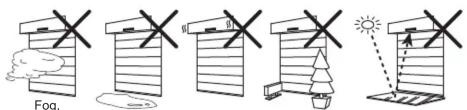
Exhaust Wet Vibration Objects
Reflection

WARNING
Danger of electric shock
Do not wash, disassemble, rebuild or repair the sensor, otherwise it may cause electric shock or breakdown of the equipment.
Specifications
| Model | : OA-4500S(E) | Activation output | : When 3rd, 4th or 5th row detects. |
| Cover color | : Black | N.C./N.O. selectable | |
| Mounting height | : 2.5 to 4.5 m (8'2" to 14'9") | 50 V 0.3 A Max. (Resistance load) | |
| Detection area | : See Detection area | Safety output | : When 1st or 2nd row detects. |
| Detection method | : Active infrared reflection | N.C./N.O. selectable | |
| Depth angle adjustment | : 1st to 3rd rows : -6 to +6°4th and 5th rows : +26 to +44° | IP rate | : 50 V 0.3 A Max. (Resistance load) |
| Power supply | : 12 to 24 VAC ±10 % (50/60 Hz) | Weight | : IP54 |
| 12 to 30 VDC ±10 % | Accessories | : 320 g (11.2 oz) | |
| Power consumption | : < 2.5 W (< 4 VA at AC) | 2 Mounting screws | |
| Operation indicator | : See Operation indicator table | 1 Mounting template | |
| Output hold time | : Approx. 500 ms | 1 Area adjustment tool | |
| Response time | : < 300 ms | 1 Cable 4.0 m (13'2") | |
| Operating temperature | : -20 to +55°C (-4 to 131°F) | ||
| Operating humidity | : < 80 % (Non-condensing) |
Operation indicator table
| Status Operation indicator color | |
| Stand-by Green | |
| 1st row detection Red | |
| 2nd to 5th row detection Orange | |
| Signal saturation Slow Green blinking | |
| Replacement signal Twice Green blinking | |
NOTE
The specifications herein are subject to change without prior notice due to improvements.
Detection area
Charts show the values in the following depth angle adjustment settings;
1st to 3rd rows : +6°
4th and 5th rows : +44°

: Emitting spots

: Emitting spots
(Can be eliminated)

: Detection area

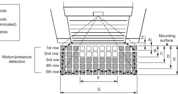
[mm(feet, inch)]
| Mounting height | 2,500 (8'2") | 3,000 (9'10") | 3,500 (11'6") | 4,000 (13'2") | 4,500 (14'9") |
| A | 160 (6") | 200 (8") | 230 (9") | 260 (10") | 290 (11") |
| B | 480 (1'7") | 580 (1'11") | 670 (2'2") | 760 (2'6") | 850 (2'9") |
| C | 930 (3'6") | 1,100 (3'7") | 1,300 (4'3") | 1,480 (4'11") | 1,660 (5'5") |
| D | 1,540 (5'1") | 1,850 (6'1") | 2,160 (7'1") | 2,460 (8'1") | 2,760 (9'1") |
| E | 2,170 (7'1") | 2,600 (8'6") | 3,030 (9'11") | 3,460 (11'4") | 3,890 (12'9") |
| F | 1,510 (4'11") | 1,810 (5'11") | 2,110 (6'11") | 2,400 (7'11") | 2,700 (8'10") |
| G | 3,150 (10'4") | 3,790 (12'5") | 4,420 (14'6") | 5,050 (16'7") | 5,680 (18'8") |
| Z | 250 (10") | 300 (12") | 350 (1'2") | 400 (1'4") 450 (1'6") |
NOTE
The actual detection area may become smaller depending on the ambient light, the color/material of the object or the floor as well as the entry speed of the object.
The sensor may not be activated when the entering speed of the object or a person is slower than 50 mm/s or faster than 1500 mm/s.
Dimensions and part names

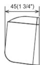
[mm(inch)]

(1) Connector
(2) Mounting holes
(3) Operation indicator
(4) Depth angle adjustment screw
(5) Width adjustment screws
(6) Dipswitches
(7) Detection window
(8) Area adjustment tool
Installation
1. Mounting
a. Affix the mounting template at the desired mounting position.
b. Drill two mounting holes ø3.4 mm (ø1/8") on the header.
c. To pass the cable through the header, drill a wiring hole of 8 mm ( 5/16" ).
![The lower edge of the header 50(1 15/16") 36(1 7/16") 25(1") 125(4 15/16") Wiring hole ø8 mm (ø5/16") Mounting holes ø3.4 mm (ø1/8") [mm(inch)]](/content/2026/06/1400214/images/723b3c9541aa3f97b9acc2f31ad18f5034fa9c0a39a50a9535a27ac51f0ed6a2.jpg)
2. Wiring
Wire the cable to the door controller.


WARNING
Danger of electric shock
Before starting the procedure, make sure that the power is turned OFF. When passing the cable through the hole, do not tear the shield otherwise it may cause electric shock or breakdown of the sensor.
3. Turn ON the power
a. Plug the connector.
b. Supply power to the sensor. Adjust the detection area and set the dipswitches.
(See Adjustments 3. Dipswitch settings)
NOTE
Make sure to connect the cable correctly to the door controller before turning the power ON.
When turning the power ON or after adjusting the settings, do not enter the detection area for more than 10 s in order to enable the presence detection.
4. Mounting the housing cover
Place the housing cover. If wiring is to be exposed, break the knockout.


WARNING
Danger of electric shock
Do not use the sensor without the cover. When using the cable knockout, install the sensor indoors or use the rain cover (Separately available) otherwise electric shock or breakdown of the sensor may occur.
Adjustments
- Area depth angle adjustment
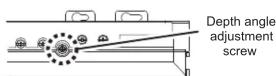

NOTE
Make sure that the detection area does not overlap with the door/header, and there is no highly reflecting object near the detection area otherwise ghosting/signal saturation may occur.
a. Independent adjustment
1st to 3rd rows
Depth angle adjustment screw for the 1st to 3rd rows.
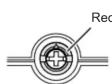
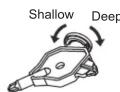
Use the area adjustment tool (A) as shown above to change the area depth angle for the 1st to 3rd rows.
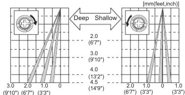
line
| Depth (mm) | [mm] | |------------|------| | 3.0 | 2.0 | | 2.0 | 3.0 | | 1.0 | 4.0 | | 0.0 | 13'2"| | 1.0 | 14'9"| | 2.0 | 6'7" | | 3.0 | 9'10"| | 4.0 | 13'2"| | 5.0 | 6'7" | | 6.0 | 3'3" | | 7.0 | 3'3" | | 8.0 | 3'3" | | 9.0 | 3'3" | | 10.0 | 3'3" | | 11.0 | 3'3" | | 12.0 | 3'3" | | 13.0 | 3'3" | | 14.0 | 3'3" | | 15.0 | 3'3" | | 16.0 | 3'3" | | 17.0 | 3'3" | | 18.0 | 3'3" | | 19.0 | 3'3" | | 20.0 | 3'3" | | 21.0 | 3'3" | | 22.0 | 3'3" | | 23.0 | 3'3" | | 24.0 | 3'3" | | 25.0 | 3'3" | | 26.0 | 3'3" | | 27.0 | 3'3" | | 28.0 | 3'3" | | 29.0 | 3'3" | | 30.0 | 3'3" | | 31.0 | 3'3" | | 32.0 | 3'3" | | 33.0 | 3'3" | | 34.0 | 3'3" | | 35.0 | 3'3" | | 36.0 | 3'3" | | 37.0 | 3'3" | | 38.0 | 3'3" | | 39.0 | 3'3" | | 40.0 | 3'3" | | 41.0 | 3'3" | | 42.0 | 3'3" | | 43.0 | 3'3" | | 44.0 | 3'3" | | 45.0 | 3'3" | | 46.0 | 3'3" | | 47.0 | 3'3" | | 48.0 | 3'3" | | 49.0 | 3'3" | | 50.0 | 3'3" | | 51.0 | 3'3" | | 52.0 | 3'3" | | 53.0 | 3'3" | | 54.0 | 3'3" | | 55.0 | 3'3" | | 56.0 | 3'3" | | 57.0 | 3'3" | | 58.0 | 3'3" | | 59.0 | 3'3" | | 60.0 | 3'3" | | 61.0 | 3'3" | | 62.0 | 3'3" | | 63.0 | 3'3" | | 64.0 | 3'3" | | 65.0 | 3'3" | | 66.0 | 3'3" | | 67.0 | 3'3" | | 68.0 | 3'3" | | 69.0 | 3'3" | | 70.0 | 3'3" | | 71.0 | 3'3" | | 72.0 | 3'3" | | 73.0 | 3'3" | | 74.0 | 3'3" | | 75.0 | 3'3" | | 76.0 | 3'3" | | 77.0 | 3'3" | | 78.0 | 3'3" | | 79.0 | 3'3" | | 80.0 | 3'3" | | 81.0 | 3'3" | | 82.0 | 3'3" | | 83.0 | 3'3" | | 84.0 | 3'3" | | 85.0 | 3'3" | | 86.0 | 3'3" | | 87.0 | 3'3" | | 88.0 | 3'3" | | 89.0 | 3'3" | | 90.0 | 3'3" | | Note: The 'Deep Shallow' label indicates the depth of the shallow region on the left axis (in mm) for each region (9'-10') and the right axis (6'-7").4th and 5th rows
Depth angle adjustment screw for the 4th and 5th rows.
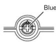

Use the area adjustment tool (B) as shown above to change the area depth angle for the 4th and 5th rows.

line
| Depth (m) | Angle (°) | |-----------|-----------| | 4.0 | 13'2" | | 3.0 | 9'10" | | 2.0 | 6'7" | | 1.0 | 3'3" | | 0 | 0 | | 2.0 | 6'7" | | 1.0 | 3'3" | | 0 | 13'9" | | 2.0 | 6'7" | | 1.0 | 3'3" | | 0 | 13'3" |b. Simultaneous adjustment
For the simultaneous adjustment of the 1st to 5th rows, use the adjustment tool (C).

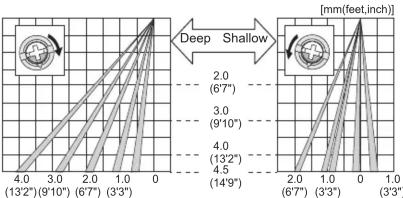
line
| Depth (mm) | Depth (ft) | | ---------- | ---------- | | 0 | 132 | | 1.0 | 97 | | 2.0 | 67 | | 3.0 | 91 | | 4.0 | 132 | | 4.5 | 149 | | 6.0 | 45 | | 7.0 | 45 | | 8.0 | 45 | | 9.0 | 45 | | 10.0 | 45 | | 11.0 | 45 | | 12.0 | 45 |Adjustments
- Area width adjustment
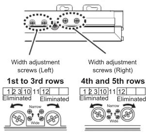
Front view

line
| Distance (mm) | Height Deviation (mm) | | ------------- | --------------------- | | 0 | 4.5 | | 1 | 4.0 | | 2 | 3.5 | | 3 | 3.0 | | 4 | 2.5 | | 5 | 2.0 | | 6 | 1.5 | | 7 | 1.0 | | 8 | 0.5 | | 9 | 0.0 | | 10 | -0.5 | | 11 | -1.0 | | 12 | -1.5 |NOTE
When adjusting the width adjustment screws, make sure to turn until it clicks otherwise the proper
operation may not be obtained.
123 cannot be eliminated separately, neither can 101112
- Dipswitch settings
□ Factory default settings
| Dip switch No. | Function | CommentSetting | ||||
| 1 | Sensitivity | Low1 22.5 to 3.5 m | Middle1 23.0 to 4.0 m | High1 25 to 4.5 m | S-High1 24.0 to 4.5 m | Please adjust the sensitivity and the presence detection timer according to your risk assessment. |
| 2 | ||||||
| 3 | Presence timer | 2 s3 4 | 60 s3 4 | 10 min3 4 | All rows have the presence detection function. To enable the presence detection, do not enter the detection area for 10 s after setting the timer. | |
| 4 | ||||||
| 5 | Frequency | Setting4 Set | Setting3 Setting in Setting 4 one sensor close to each other, set the frequency different for each sensor. | |||
| 6 | 65 65 | 65 65 | ||||
| 7 | Row adjustment | 5 rows7 8 | 3 rows7 8 | 2 rows7 8 | Set the depth rows with dipswitches 7 and 8.When "2 rows" are selected, the activation output is disabled. | |
| 8 | ||||||
| 9 | Door cancel | OFF9 | ON9 | When dipswitch 9 is "ON" the sensor is less influenced by the door movement, i.e. caused by wind.If the sensor does not detect for 10 s, the 1st row will be disabled when door cancel function is "ON". (The 1st row will be enabled again when there is detection at other rows.)WARNINGRisk of getting caughtWith this fuction, 1st row is disabled if there are no ditection for 10 s.If a person or vehicle enter the 1st row without any detection in other rows (e.g. enter from the other side), it might cause an accident. | ||
| 10 | On delay 2sec. | OFF10 | ON10 | |||
| 11 | Automatic infinite presence detection | OFF11 | ON11 | To avoid unnecessary openings due to passing objects/persons set dipswitch 10 to "ON". The sensor only activates when a person or object stays in the detection area for more then 2 s.WARNINGRisk of getting caughtPlease do not set On delay 2sec. to "ON" when door cancel function is "ON".If both are "ON", the sensor does not output signal unless it detects a person or object more than 2 s and 1st row is inactive.If the person or object enter the 1st row, the sensor does not detect and door never opens. | ||
| 12 | Presence area | 1st to 5th12 | 1st & 2nd12 | |||
| 13 | Activation output | N.O.13 | N.C.13 | When people or objects enter more than 2 spot areas, this function automatically sets the presence timer to infinity to increase safety and avoid unwanted door opening due to sudden change in floor condition. | ||
| 14 | Safety output | N.O.14 | N.C.14 | |||
| 15 | Simultaneous output | OFF15 | ON15 | The activation and safety outputs can be selected separately. | ||
Dipswitch 16 is not used.
Checking
Check the operation in the operation mode according to the chart below.
| Entry | Power OFF | Outside of detection area | Entry into 3rd to 5th row | Entry into 2nd row | Entry into 1st row | ||
| Status | - | Stand-by | Motion/presence detection | ||||
| Operation indicator | None | Green | Orange | Red | |||
| Simultaneous outputOFF15 | Activation output | N.O.13 | |||||
| N.C.13 | |||||||
| Safety output | N.O.14 | ||||||
| N.C.14 | |||||||
| Simultaneous outputON15 | Activation output | N.O.13 | |||||
| N.C.13 | |||||||
| Safety output | N.O.14 | ||||||
| N.C.14 | |||||||
Inform building owner/operator of the following items
! WARNING
- Always keep the detection window clean. If dirty, wipe the window with a damp cloth.
Do not use any cleaner/solvent. - Do not wash the sensor with water
- Do not disassemble, rebuild or repair the sensor yourself, otherwise an electric shock may occur.
- When the operation indicator is Green blinking, contact your installer or service engineer.
- Always contact your installer or service engineer when changing the settings.
- Do not paint the detection window.
NOTE
- When turning the power ON, alwayswalk-test the detection area to ensure the proper operation.
- Do not place any objects that move oredit light in the detection area. (e.g. plant, illumination, etc.)
Troubleshooting
| Door operation | Operation indicator | Possible cause | Possible countermeasures |
| Door does not open when a person enters the detection area. | None | Wrong power supply voltage. | Set to the stated voltage. |
| Wrong wiring or connection failure. | Check the wires and connector. | ||
| Unstable | Wrong detection area positioning. | Check Detection area & Adjustments. | |
| Sensitivity is too low. | Set the sensitivity higher. | ||
| Short presence timer. | Set the presence timer longer. | ||
| Dirty detection window. | Wipe the detection window with a damp cloth. Do not use any cleaner or solvent. | ||
| Proper | Wrong wiring or connection failure. | Check the wires and connector. | |
| Green | Wrong (Safety/Activation) output setting. | Check the dipswitch 13 to 15. | |
| Both on delay and door cancel function are "ON". | Set either function to "OFF". Check the dipswitch 9,10. | ||
| Orange Wrong wiring. | Check the wires and connector. | ||
| Door opens when no one is in the detection area. (Ghosting) | Unstable | Objects that move or emit light in the detection area. | Remove the objects. |
| The detection area overlaps with that of another sensor. | Check the dipswitch 5, 6. | ||
| Waterdrops on the detection window. | Use the rain-cover. (Separately available) Or wipe the detection window with a damp cloth. Do not use any cleaner or solvent. Or install in a place keeping the waterdrops off. | ||
| The detection area overlaps with the door/header. | Adjust the detection area to "Deep" (Outside). | ||
| Sensitivity is too high. | Set the sensitivity lower. | ||
| Wrong (Safety/Activation) output setting. | Check the dipswitch 13 to 15. | ||
| Door remains open. | Proper | Presence timer is "∞" or sudden change in the detection area. | Check the dipswitch 3, 4, 11. If the problem still persists, hard-reset the sensor.(Turn the power OFF and ON again.) |
| Wrong wiring or connection failure. | Check the wires and connector. | ||
| The automatic infinite presence detection is "ON" and the objects or people enter more than two spot areas. | Remove the objects. Or the dipswitch 11. | ||
| Green | Wrong (Safety/Activation) output setting. | Check the dipswitch 13 to 15. | |
| Proper operation | Twice Green blinking | Replacement signal. | Contact your installer or service engineer. |
| Slow Green Blinking | Signal saturation. | Remove highly reflecting objects from the detection area. Or lower the sensitivity. Or change the area depth angle. | |
| The detection area overlaps with the door/header. | Adjust the detection area to "Deep" (Outside). | ||
Contact
Europe, Middle-East and Africa Subsidiary
OPTEX TECHNOLOGIES B.V.
Henricuskade 17, 2497 NB The Hague, The Netherlands
www.optex-europe.com Tel: +31(0)70 419 41 00
North and South America Subsidiary
OPTEX INCORPORATED
10741 Walker Rd. Suite 300 Cypress, CA 90630 U.S.A
www.optexamerica.com Tel: +1(800)877 6656


Manufacturer
OPTEX CO., LTD.
5-8-12, Ogoto, Otsu, Shiga, 520-0101 Japan
Legal representative (UK only)
OPTEX (EUROPE) LTD.
Unit 13 Cordwallis Park Clivemont Road SL6 7BU Maidenhead, Berkshire United Kingdom
- Manufacturer's statement
- NOTE
- WARNING
- Danger of electric shock
- Detection area
- Installation
- Mounting
- Wiring
- Turn ON the power
- Mounting the housing cover
- Adjustments
- a. Independent adjustment
- 1st to 3rd rows
- 4th and 5th rows
- b. Simultaneous adjustment
- Checking
- Inform building owner/operator of the following items
- ! WARNING
- Contact
- Manufacturer
Marque : OPTEX
Modèle : OA-4500
Catégorie : Capteur de porte / fenêtre