JA-63E - Caméra de surveillance Jablotron - Notice d'utilisation et mode d'emploi gratuit
Retrouvez gratuitement la notice de l'appareil JA-63E Jablotron au format PDF.


| Type de produit | Caméra de surveillance |
| Marque | Joblotron |
| Modèle | JA-63E |
| Dimensions (L x l x H) | 7 x 7 x 12 cm |
| Poids | 200 g |
| Alimentation | 12 V CC, adaptateur secteur inclus |
| Résolution | 1080p Full HD |
| Angle de vue | 90° |
| Vision nocturne | Oui, jusqu'à 10 mètres |
| Détection de mouvement | Oui, avec notification push |
| Audio bidirectionnel | Oui, microphone et haut-parleur intégrés |
| Connectivité | Wi-Fi 2.4 GHz, Ethernet |
| Stockage | Carte microSD jusqu'à 128 Go, cloud optionnel |
| Indice de protection | IP65 (résistant aux intempéries) |
| Installation | Murale ou sur support, fixation incluse |
| Entretien et nettoyage | Nettoyer la lentille avec un chiffon doux et sec |
| Sécurité | Cryptage des données, accès par mot de passe |
| Pièces détachées et réparabilité | Câble d'alimentation, supports, visserie disponibles |
| Température de fonctionnement | -10°C à 50°C |
| Garantie | 2 ans |
FOIRE AUX QUESTIONS - JA-63E Jablotron
Questions des utilisateurs sur JA-63E Jablotron
0 question sur cet appareil. Repondez a celles que vous connaissez ou posez la votre.
Poser une nouvelle question sur cet appareil
Téléchargez la notice de votre Caméra de surveillance au format PDF gratuitement ! Retrouvez votre notice JA-63E - Jablotron et reprennez votre appareil électronique en main. Sur cette page sont publiés tous les documents nécessaires à l'utilisation de votre appareil JA-63E de la marque Jablotron.
MODE D'EMPLOI JA-63E Jablotron
The JA-63E digital bus wired keypad
The JA-63E keypad is designed to control and program alarm systems of Jablotron's JA-6x series. The keypad is equipped with backlit keys, built-in LED signalling, acoustic signalling, and a display. It conveys information about the system status in a convenient way. The keypad communicates via the control panel digital bus. You can connect the keypad to the control panel via an RJ cable or via a standard communication cable connected to terminals. Multiple JA-63E keypads can be connected to a single control panel.
Any undesirable mishandling of the keypad (like opening its housing or tearing the keypad off its position) will trigger tamper signalling. In addition, the number of attempts to enter an access code is checked not to exceed a given limit.
Installation
Select the desired keypad location close to the building's entrance.
- Open the keypad's rear housing (by pressing the two tabs on the left or right side).
- Route all required cables through the hole in the rear housing and install the housing to the desired location.
- Connect the digital bus cable either to the terminal board or to an RJ connector.
- Close the keypad's housing (attach the front housing on one side and push it on the other side).
- Switching on the control panel power makes the keypad ready for operation.
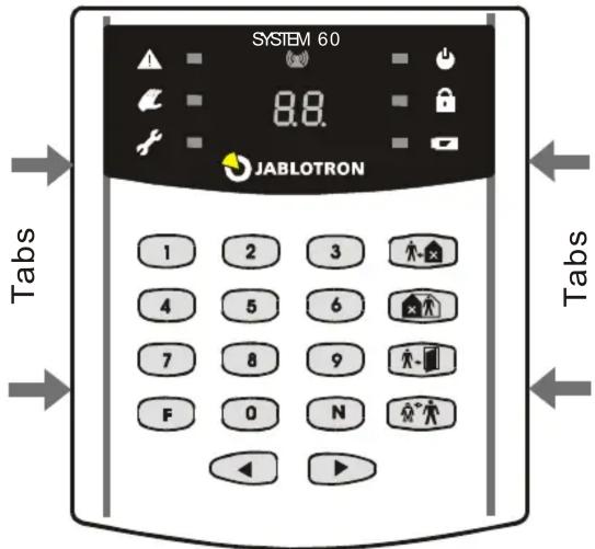
Installation notes:
Multiple JA-63E keypads in the system must be wired in parallel. Inlet cables can be split directly in the control panel, in a converter, in the keypad or in a junction box. RJ cable connection and connection to terminals can be used in combination.
A connecting cable must be wired so that the corresponding positions (terminals) are connected. When you use a self-made RJ cable, be careful to connect identically coloured wire ends to identically marked positions (terminals).
If the keypad does not function after being connected, disconnect the inlet cable and check if the corresponding positions (terminals) in the control panel and the keypad are connected.
Operation
The keypad can operate and program the system to the full extent as it is described in the control panel manual.
The following table describes the meaning of symbols on the keypad LED indicators:
| Alarm | Power supply | ||
| Tamper | Set (Armed) | ||
| Fault | Battery | ||
| Wireless communication indication | |||
Functions F1 through F0 can be used as described in the control panel manual. Besides this, there are 4 extra keys with the following functions:
 | Setting (Arm-ing)(equal to F1 entry) |  | Door opening(equal to F3 entry) |
 | Partial setting(equal to F2 entry) |  | Panic (access under duress)(equal to F7, before access code entry) |
Remote system access
The JA-63E keypad allows you to remotely operate or program a JA-6x system via a phone line using a JA-60U modem. Such operation requires the system to be equipped with a telephone communicator with the remote access feature enabled (see the security system installation manual).
Note: Remote system access via the JA-63E keypad is only possible using a JA-60U modem of DY62012 version or higher.
Connecting remotely to the system: Connect the JA-60U modem to the phone line. Connect the JA-63E keypad cable to the modem's data connector. After powering up the modem, the keypad will show a u on the display to indicate that it is ready to establish a connection.
The initial connection is established by keying in:
xxxxxxxx F1 y F2 ttt...t F3 nnn...n F d
where:
xxxxxxxx is an 8-digit access code for system remote access
y answering machine bypass (a so-called second call) 0-not bypassed, 1-bypassed
ttt...t call back tel. number – if call back is not requested just enter F3 after F2
nnn...n the remote system tel. number (a pause can be specified by keying in F0)
d dialling method: 4-tone, 5-pulse
After the d parameter is entered, the modem will establish a connection and the keypad will display the remote system status. The keypad then behaves the same way as if it had been connected directly to the system. Depending on the quality, the telephone line might be slower in its response. A JA-63 remote connection disables the 4 big keys on the keypad's right side. Use keys F0 to F9 instead.
The connection is terminated by pressing key

A re-connection (using the same modem) is established by entering F6. The connection parameters are memorized.
If you perform a call to a control panel which has the same access code but a different telephone number, you do not need to re-enter the whole connecting sequence. Instead, it is sufficient to key in nnn...n F4 – i.e. the control panel tel. number followed by one of the F4/F5 keys (depending on the tone/pulse dialling method).
Technical specifications
| Connection | with a cable to the JA-6x digital bus connector |
| Connecting cable | 4 core cable with RJ connectors (4/4 1:1) or ordinary telephone cable (terminals) |
| Length of the inlet cable | max. 100 m when a paired cable is used |
| Power supply | 10 –14 V (taken from the digital bus) |
| Power consumption | 25mA |
| Enclosure | IP40 |
| Dimensions | 125 x 145 x 30 mm |
| Complies with | EN 50131-1, EN 50131-3 grade 2 |
| Environmental class | II indoor general -10 to +40°C |
| EMC | EN 50130-4,EN 55022 |
| Contents of the kit: | JA-63E keypad, 4 m of connecting cable, 4 rawl plugs, 4 screws, 2 RJ-44 connectors. |
| Accessories – for keypad connection (can be ordered separately): | |
| RJ-40 | converter from RJ connector to 4 terminals |
| RJ-21 | RJ connector splitter (2/1) |
| RJ-44 | cable connector (4P/4C) |
| RJ-00 | crimping tool for RJ connectors |
| CT-04 | cable for RJ connectors |


JABLOTRON ALARMS a.s hereby declares that the JA-63E is in compliance with the essential requirements and other relevant provisions of Directive 2004/108/EC. The original of the conformity assessment can be found at www.jablotron.com, Technical Support section.
Note: Although this product does not contain any harmful materials we suggest you return the product to the dealer or directly to the producer after use. See www.jablotron.com for details.

JABLOTRON ALARMS a.s.
Pod Skalkou 4567/33
46601 Jablonec nad Nisou
Czech Republic
Tel.: +420 483 559 911
Fax: +420 483 559 993
Internet: www.jablotron.com
Marque : Jablotron
Modèle : JA-63E
Catégorie : Caméra de surveillance