A-880 - Contrôleur MIDI ROLAND - Notice d'utilisation et mode d'emploi gratuit
Retrouvez gratuitement la notice de l'appareil A-880 ROLAND au format PDF.

| Type de produit | Contrôleur MIDI / Patchbay / Mixeur MIDI |
| Marque | Roland |
| Modèle | A-880 |
| Entrées MIDI | 8 (prises DIN 5 broches) |
| Sorties MIDI | 8 (prises DIN 5 broches) |
| Fonctions principales | Routage, mixage, sauvegarde de 64 configurations, filtrage de messages MIDI, contrôle à distance par program change |
| Mémoire interne | 64 emplacements (8 banques × 8 numéros) |
| Filigrane MIDI | Filtre par type de message (Note, Aftertouch, Control Change, Program Change, etc.) |
| Indicateurs lumineux | 8 × entrée/banque, 8 × sortie/numéro, Signal, Scan/Mix, Memory, Write |
| Boutons | 8 × entrée/banque, 8 × sortie/numéro, Signal, Scan/Mix, Memory, Write |
| Dimensions | 482 × 44 × 286 mm (19" × 1,75" × 11,25") |
| Poids | 3 kg |
| Alimentation | Secteur 5 W, cordon avec prise de terre |
| Tension secteur | Selon plaque signalétique (100–240 V selon version) |
| Consommation | 5 W |
| Batterie de sauvegarde | Lithium, doit être remplacée tous les 5 ans par un technicien |
| Nettoyage | Chiffon doux et sec, éventuellement légèrement humide avec détergent neutre |
| Sécurité | Mise à la terre obligatoire, ne pas utiliser près de l'eau, débrancher en cas d'orage |
| Température d'utilisation | Éviter chaleur excessive, humidité, lumière directe et poussière |
| Réparabilité | Confier à un technicien qualifié pour toute réparation interne (batterie, cordon endommagé, etc.) |
| Accessoires inclus | Cordon d'alimentation, manuel d'utilisation |
FOIRE AUX QUESTIONS - A-880 ROLAND
Questions des utilisateurs sur A-880 ROLAND
0 question sur cet appareil. Repondez a celles que vous connaissez ou posez la votre.
Poser une nouvelle question sur cet appareil
Téléchargez la notice de votre Contrôleur MIDI au format PDF gratuitement ! Retrouvez votre notice A-880 - ROLAND et reprennez votre appareil électronique en main. Sur cette page sont publiés tous les documents nécessaires à l'utilisation de votre appareil A-880 de la marque ROLAND.
MODE D'EMPLOI A-880 ROLAND
A-880
Owner's Manual


The lightning flash with arrowhead symbol, within an equilateral triangle, is intended to alert the user to the presence of uninsulated "dangerous voltage" within the product's enclosure that may be of sufficient magnitude to constitute a risk of electric shock to persons.
The exclamation point within an equilateral triangle is intended to alert the user to the presence of important operating and maintenance (servicing) instructions in the literature accompanying the product.
INSTRUCTIONS PERTAINING TO A RISK OF FIRE, ELECTRIC SHOCK OR INJURY TO PERSONS.
IMPORTANT SAFETY INSTRUCTIONS
WARNING When using electric products, basic precautions should always be followed, including the following;
- Read all the instructions before using the product.
- Do not use this product near water- for example, near a bathtub, washbowl, kitchen sink, in a wet basement, or near a swimming pool, or the like.
- This product should be used only with a cart or stand that is recommended by the manufacture.
- This product, either alone or in combination with an amplifier and headphones or speakers, may be capable of producing sound levels that could cause permanent hearing loss. Do not operate for a long period of time at a high volume level or at level that is uncomfortable. If you experience any hearing loss or ringing in the ears, you should consult an audiologist.
- The product should be located so that its location or position does not interfere with its proper ventilation.
- The product should be located away from heat sources such as radiators, heat registers or other products that produce heat.
- The product should avoid using in where it may be effected by dust.
- The product should be connected to a power supply only of the type described in the operating instructions or as marked on the product.
9 The power-supply cord of the product should be unplugged from the outlet when left unused for a long period of time.
10. Do not tread on the power-supply cord.
11. Do not pull the cord but hold the plug when unplugging.
12. When setting up with any other instruments, the procedure should be followed in accordance with instruction manual.
13. Care should be taken so that objects do not fall and liquids are not spilled into the enclosure through openings.
14. The product should be serviced by qualified service personnel when:
A: The power-supply cord or the plug has been damaged; or
B: Objects have fallen, or liquid has been spilled into the product; or
C: The product has been exposed to rain; or
D: The product does not appear to operate normally or exhibits a marked change in performance; or
E: The product has been dropped, or the enclosure damaged.
15 Do not attempt to service the product beyond that described in the user-maintenance instructions. All other servicing should be referred to qualified service personnel.
SAVE THESE INSTRUCTIONS
GROUNDING INSTRUCTION
This product must be grounded. If it should malfunction or breakdown, grounding provides a path of least resistance for electric shock. This product is equipped with a cord having an equipment-grounding plug. The plug must be plugged into an appropriate outlet that is properly installed and grounded in accordance with all local codes and ordinances.
DANGER - Improper connection of the equipment-grounding conductor can result in a risk of electric chock. Check with a qualified electrician or servicer when you are in doubt as to whether the product is properly grounded. Do not modify the plug provided with the product - if it will not hit the outlet, have a proper outlet installed by a qualified electrician.
ADVARSEL!
Lithiumbatteri. Eksplosionsfare.
Udskiftning m' kun foretages af en sagkyndig,
og som beskrevet i servicemanual.
WARNING!
Lithiumbatteri. Explosionsrisk.
Fáendastbytasavbehörngserviceteekniker.
Se instruktioner i servicemanualen.
ADVARSEL!
Lithiumbatteri. Fare for eksploitation.
Ma bare skiftes av kvalisert tekniker som
beskrevetiservicemanualen.
VAROITUS!
Lithiumparisto. Rajahydysvaara.
Pariston saa vaihtaa ainostaan
alan ammottimies.
WARNING
THIS APPARATUS MUST BE EARTH GROUNDED.
The three conductors of the mains lead attached to this apparatus are identified with color as shown in the table below, together with the matching terminal on the UK type power plug. When connecting the mains lead to a plug, be sure to connect each conductor to the correct terminal, as indicated.
"This instruction applies to the product for United Kingdom."
| MAINS | LEADS | PLUG |
| Conductor | Color | Mark on the matching terminal |
| Live | Brown | Red or letter L |
| Neutral | Blue | Black or letter N |
| Grounding | Green- Yellow | Green, Green-Yellow, letter E or symbol |
Bescheinigung des Herstellers /Importeurs
Hiermit wird beschrieben, daß der/die/das
ROLAND MIDI PATCHER/MIXER A-880
Grral yw Bezektwngi
in Ubereinstimmung mit den Bestimmungen der
Amtsbl. Vfg 1046:1984
(Ambient Verlagung)
funk-entstart
Der Deutschen Bundespost wurde das Inverkehringen des Georas angezeigt und die Berechtigung zur Überprüfung der Serie auf Einhaltung der Bestimmungen eingeraumt
Roland Corporation Osaka Japan
Maae ne stnne ples mss
RADIO AND TELEVISION INTERFERENCE
Warning This equipment has been verified to comply with the Iursies for a Class B computing device. The device is not intended to be used in a commercial or industrial context. Non-certified or non-verified equipment is likely to result in interference to radio and IV reac
The equipment described in this manual generates and uses radio-frequency energy. It is not intended and used properly. Prior to its use, it may cause interference with the operation of the system.
This equipment has been tested and found to comply with the limits for Class B computing applications. The equipment is designed to be used in a residential setting, where it is intended to be used as a portable device. It is designed to provide reasonable protection against such a interference in a residential installation. This equipment is designed to be used in an office setting, where it is intended to be used as a portable device. The equipment does cause interference in radio or television reception, which can be determined by turning the equipment on and off the user is encouraged to try to correct the interference by the equipment itself.
- Disconnected other devices and their input output cables are at a time. If the interference stops, it is caused by either the offset device or its I/O cable
Helps visually, require Roland designation shortened to 1 C boxes for Roland devices. You can also add a modified table from your dealer. For non Roland devices contact the manufacturer or dealer for assistance.
If you equipment does cause interference to radio or television reception, you can try to contact the interference by using one or more of the following measures.
Turn the IV or radio antenna until the interference mode.
-
Move the equipment (either away from the TV or inside)
-
Plug the equipment into an outlet that is on a different circuit than the TV or radio. That is, make it present the equipment and the radio of television set are all controls controlled by different units.
-
Consider installing a rooftop television antenna with cable cable length in between the antenna and TV.
If necessary, you should confirm your decision to an experienced radio talk show host for additional suggestions. You may find helpful the following booklet prepared for the Federal Govt:
Hn n n
The haild in available from the 55 Government Pnent Office Wssington E1 26437
Thank you for purchasing the Roland MIDI Patcher/Mixer A-880.
The A-880 is provided with eight independent MIDI IN's and OUT's. You can select any of those IN and OUT sockets, and also mix MIDI messages from two MIDI IN's and send them from more than one MIDI OUT's. Moreover, the A-880 allows you to select whether or not to send MIDI messages from each MIDI output socket and features some more useful MIDI functions.
To make the best use of this unit, read this owner's manual carefully.
CONTENTS
Important Notes 4
- Panel Description 6
- Changing Connections 7
3.Mixing 7 - Writing the Connections into Memory 8
- Recalling a Memory and Changing Memories... 9
- MIDI Message Filter 10
- Other Useful Functions 11
- Setup Examples 11
A-880 Table 12
■ Initialization 12
■MIDI Implementation 13
■ Specifications 20
IMPORTANT NOTES
Power Supply
The appropriate power supply for this unit is shown on its name plate. Please make sure that the line voltage in your country meets this requirement.
-Do not use the same socket used for any noise generating device (such as a motor or variable lighting system).
Make sure that the unit is turned off before connecting the power plug to the AC socket.
- When disconnecting the power plug from the socket, do not pull the cord, but hold the plug to avoid damaging the cord.
Avoid damaging the power cord.
If the unit is not to be used for a long period of time, unplug the cord from the socket.
It is normal for this unit to become hot while being operated.
Check with your local Roland dealer if you wish to use this unit in a foreign country.
Disconnect the AC cord immediately in the event of an electrical storm.
Connections
Room Location
Before setting up this A-880 with other MIDI devices, turn this unit off along with all other units.
- Avoid using this device in excessive heat or humidity conditions, or where it may be affected by direct sunlight or dust and avoid places subject to high vibration.
-Operating the unit near a neon light, fluorescent lamp, TV or CRT Display may cause noise interference. If so, change the angle or the position of the unit.
-Operating this unit near a TV or radio may cause picture or noise interference. If this happens, move the unit away from these instruments.
Do not place or drop anything heavy on the main unit or its power cord.
Cabinet, Cleaning Care
Memory Backup System
For cleaning the unit, use a dry and soft cloth.
- If the casing is stained, use a cloth slightly dampened with water.
To remove stubborn stains, clean the casing with a cloth moistened with a neutral detergent, then wipe it dry with a soft cloth.
Do not use solvents such as paint thinner.
This unit features a memory back-up system that retains the data even after switched off. The battery that supports the back-up circuit should be replaced every five years. Call the Roland service station for a battery replacement. (The first replacement may be required before five years, depending on how much time had passed before you purchased the unit.)
- When the battery is exhausted, all indicators flicker when power is turned on. At such times there is a possibility that the backup memory has been lost (See Page 12).
Although we do our utmost to protect your data during repairs, sometimes, especially when working on the memory itself or on a related area, some of your important data may be lost. Keep a separate record of all the data that you consider important. This can be done by saving it down on a sheet of paper.
How To Handle The Unit
Do not allow fluid or foreign matter, such as water, beverages, coins and wires, to enter this unit.
Do not examine or modify the internal components or circuitry. Electrical shocks or damage may result.
Do not subject this unit to strong shocks, or move it while the power is on.
If this unit fails to operate correctly, turn it off immediately and contact your Roland dealer.
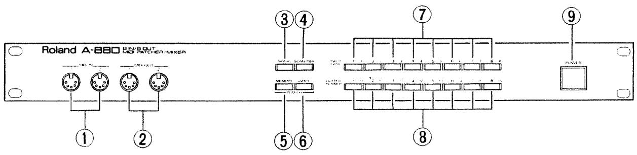
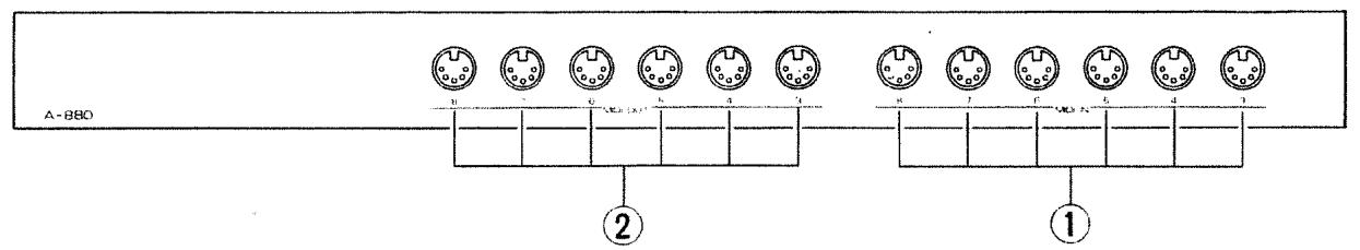
①MIDI IN Sockets (1 - 8)
②MIDI OUT Sockets (1 - 8)
③ Signal Mode Button
Pushing this button will light up the indicator and turn the unit to the Signal mode. In the Signal mode, the relevant Input/Bank Buttons and Output/Number Buttons light up when MIDI messages are being fed into the unit. This fact allows you to check how the inputs and outputs have been currently connected.
④ Scan/Mix Mode Button
Pushing this button will light up the indicator and turn the unit to the Scan mode. In the Scan mode, you can check the current MIDI In and Out settings in sequence (Mix Input 1 Input 2 ...) with the indicators of the Input/ Bank and Output/ Number Buttons.
This button can also be used for mixing signals.
⑤Memory Mode Button
This button is used to call any setting written in memory.
⑥Write Mode Button
This button is used to write a setting you have made into memory.
⑦ Input/Bank Buttons (1-8)
These buttons are used for selecting MIDI IN's or a Memory Bank.
⑥ Output/Number Buttons (1-8)
These buttons are used for selecting MIDI OUT's or a Memory Number.
⑨Power Switch
2 Changing Connections
The connections of each MIDI IN and MIDI OUT can be changed as follows:
*More than one MIDI OUT can be assigned to one MIDI IN, but more than one MIDI IN (including Mix Input) cannot be assigned to the same MIDI OUT. If you assign a MIDI IN to a MIDI OUT already used for another MIDI IN, the later MIDI IN will override the previous one.
① Press the Scan/Mix or Signal Button.
The corresponding indicator lights up.
②Press the Input/Bank Button for the MIDI IN to be connected.
All the Mode Buttons go out and the Output/ Number Buttons which correspond to the MIDI OUT's currently used will light up.
③Press the Output/Number Buttons for the MIDI OUT's you wish to use.
The indicators light up, activating the corresponding MIDI OUT's.
*Be sure to assign MIDI OUT's within 15 seconds after taking step ②. Otherwise, you will go back to step ①.
*Do not take the above MIDI OUT assignment procedure while MIDI messages are being received or transmitted.
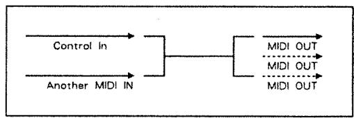
3 Mixing
The mixing function of the A-880 allows you to mix the MIDI messages of the base MIDI IN (Control In) with the messages of another MIDI IN and send the mixed messages.
*If you assign MIDI OUT's already used, the previous assignment will be cancelled.
【Setting a Control IN】
Turn the unit off, then turn it on while holding the Input Button down which corresponds to the MIDI IN which you wish to make a Control IN.
*The Control In you have set will be retained even after the unit is turned off.
[Connecting the MIX Inputs]
① While holding the Scan/Mix Button down, press the Input/Bank Button for the MIDI IN you wish to mix.
One of the Input/Bank Button lights while the other one flashes.
② Press the Output/Number Buttons for the MIDI OUT's where the mixed messages are to be sent.
The Output / Number Buttons light up, activating the corresponding outputs (MIDI OUT's).
To turn off the MIDI OUT's you have set, press the Output/Number Buttons which are lit.
4 Writing the Connections into Memory
The Mixing function does not allow you to input MIDI clock messages from the two MIDI IN's at the same time. The MIDI IN where the MIDI clock messages are input flashes. To select another MIDI IN: press the Input/Bank Button which you have assigned in step ① while holding the Scan/Mix Button.
You can select any MIDI IN for mixing, but if the selected MIDI IN is the same as the Control In, the function of mixing does not work. The indicator of the Input/Bank Buttons selected here will flash, showing that the MIDI clock messages can be input.
*Be sure to complete step ③ procedure within 15 seconds after taking step ②. Otherwise, the unit will go back to the Signal or Scan mode.
If you wish to retain the connection assignment you have made, write it into any of the 64 memory locations. A memory location is represented by a Memory Bank (1 - 8) and Memory Number (1 - 8), such as 2 - 3, 4 - 8, etc.
| Bank | 1 | 2 | 3 | 4 | 5 | 6 | 7 | 8 |
| 1 | 11 | 12 | 13 | 14 | 15 | 16 | 17 | |
| 2 | 21 | 22 | 23 | 24 | 25 | 26 | 27 | |
| 3 | 31 | 32 | 33 | 34 | 35 | 36 | 37 | |
| 4 | 41 | 42 | 43 | 44 | 45 | 46 | 47 | |
| 5 | 51 | 52 | 53 | 54 | 55 | 56 | 57 | |
| 6 | 61 | 62 | 63 | 64 | 65 | 66 | 67 | |
| 7 | 71 | 72 | 73 | 74 | 75 | 76 | 77 | |
| 8 | 81 | 82 | 83 | 84 | 85 | 86 | 87 |
① Press the Write Button.
The indicator lights up.
② Assign a memory location with the Input/ Bank (banks 1-8) and Output/ Number (numbers 1-8) Buttons.
③Press the Write Button.
④ Press the Scan/Mix or Signal Button.
*The Control In is not written with each memory number. This means that changing the settings of the Control In at power-up will change the mixing assignment.
5 Calling a Memory and Changing Memories
The connection setting you have written into memory can be recalled as follows.
【Calling a Memory】
① Press the Memory Button.
The indicator lights up.
② Assign the memory you wish to call with the Input/ Bank (Banks 1 - 8) and Output/ Number (Numbers 1 - 8) Buttons.
If you assign the Bank first, you must assign the Number next even if you do not need to change the Number. However, if you assign the Number first, you can skip bank assignment if you do not need to change the Bank.
③Press the Scan/Mix or Signal Button.
*When the memory you have called has the same Mix In and Control In, the function of Mix does not work.
[Changing Memories from an external MIDI device]
To change memories from an external MIDI device, use the Program Change messages of the MIDI channel (Control Channel) assigned at the Control In (see page 7).
Setting the Control Channel
①Press the Memory and Write Buttons at the same time.
The two indicators light up.
② Specify the Control Channel using the Input/ Bank and Output/Number Buttons.
The Input/Bank Buttons 1 to 8 correspond to Control Channels 1 to 8 and the Output/Number Buttons 1 to 8 correspond to Control Channel 9 to 16.
| INPUT/BANK | 1 | 2 | 3 | 4 | 5 | 6 | 7 | 8 |
| OUTPUT/NUMBER | 9 | 10 | 11 | 12 | 13 | 14 | 15 | 16 |
*If you do not wish to change the memories with Program Change messages, press the Input/ Bank and Output/ Number Buttons which are lit. (The indicator will go out).
③Press the Scan/Mix or Signal Button.
■Program Change Numbers and Memory Numbers
The Memory Numbers on the A-880 correspond to the Program Change numbers as shown below. Any program change number higher than 65 will have no effect on the memory numbers.
| Bank | Number | |||||||
| 1 | 2 | 3 | 4 | 5 | 6 | 7 | 8 | |
| 1 | 1 | 2 | 3 | 4 | 5 | 6 | 7 | 8 |
| 2 | 9 | 10 | 11 | 12 | 13 | 14 | 15 | 16 |
| 3 | 17 | 18 | 19 | 20 | 21 | 22 | 23 | 24 |
| 4 | 25 | 26 | 27 | 28 | 29 | 30 | 31 | 32 |
| 5 | 33 | 34 | 35 | 36 | 37 | 38 | 39 | 40 |
| 6 | 41 | 42 | 43 | 44 | 45 | 46 | 47 | 48 |
| 7 | 49 | 50 | 51 | 52 | 53 | 54 | 55 | 56 |
| 8 | 57 | 58 | 59 | 60 | 61 | 62 | 63 | 64 |
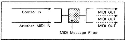
6 MIDI Message Filter
You can edit out certain portions of the MIDI messages of the mixed signal by using the MIDI Message Filter.
The MIDI Message Filter also works when the Control In and the MIDI IN for mixing are set to the same number.
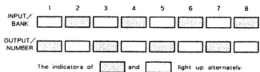
①Press the Signal and Scan/Mix Buttons at the same time.
The two indicators light up.
② By using the Input/ Bank Buttons 7 and 8 and Output/ Number Buttons 1 to 8, the output On or Off can be selected.
Each time you press the button, the indicator lights up and goes out alternately. When the indicator is lit, the corresponding MIID messages are output, and when it goes out, messages are not output.
③Press the Signal or Scan/Mix Button.
INPUT 7 Whether or not to output ALL NOTE OFF messages from the MIDI OUT.
INPUT 8 Whether or not to re-trigger the Notemessage from the MIDI IN and sendit through the MIDI OUT. (when a new NOTE ON is assigned to the same note number, NOTE - OFFcomes once, then NOTE-ON)
OUTPUT 1 Whether or not to send the Note ON /OFF messages from the MIDI OUT.
OUTPUT 2 Whether or not to send the Polyphonic Pressure messages (aftertouch messages which can be assigned to each Note Number independently) from the MIDI OUT.
OUTPUT 3 Whether or not to send the Control Change messages from the MIDI OUT.
OUTPUT 4 Whether or not to send the Program Change messages from the MIDI OUT.
OUTPUT 5 Whether or not to send the Channel Pressure messages (aftertouch messages which can be independently assigned to each MIDI channel) from the MIDI OUT.
OUTPUT 6 Whether or not to send the Pitch Bender messages from the MIDI OUT.
OUTPUT 7 Whether or not to send the Exclusive messages from the MIDI OUT.
OUTPUT 8 Whether or not to send the Real Time and Common messages from the MIDI OUT.
7 Other Useful Functions
Four more useful functions. Inputs 1 to 4, are provided.
①Press the Signal and Scan/Mix Buttons at the same time.
The two indicators light up.
② The INPUT 1 to 4 functions are engaged when you press the relevant buttons.
③Press the Signal or Scan/Mix Button.
INPUT 1 The entire connection assignment is cancelled. This function can be used to start setting from scratch.
INPUT 2 The Mixer Inputs are cancelled and the Mixer reset. If the mixed MIDI messages include any NOTE - ON key, NOTE OFF will be sent from the MIDI OUT.
INPUT 3 ALL Note OFF and RESET ALL CONTROLLERs are sent from each MIDI OUT to all the channels. This function can be used to initialize the connected MIDI devices.
INPUT 4 TUNE REQUEST and A4 KEY ON are transmitted intermittently from each MIDI OUT. This can be used for tuning the connected MIDI devices.
8 Setup Examples
1) Setup with a MIDI Keyboard and three MIDI Sound Sources
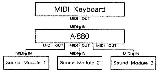
You can play multiple MIDI sound sources with one MIDI keyboard.
2) Setup with a MIDI keyboard, a Sequencer and a MIDI Sound Source
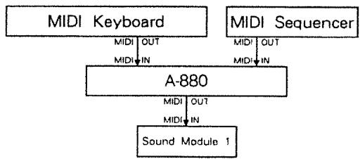
By using the Mixing function of the A-880, MIDI messages from the MIDI keyboard and sequencer are mixed and play the MIDI sound source.
3) Setup with two Sequencers
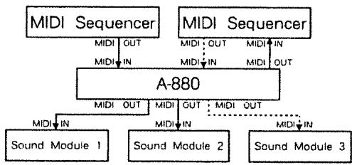
These two sequencers are used as a master and a slave. When they are synchronizing, the master sequencer plays the sound sources 1 and 2, and the slave sequencer plays the sound source 3.
A-880 Table
- When the amount of mixed MIDI messages exceeds the maximum capacity of the A-880, the buttons will react as shown below:
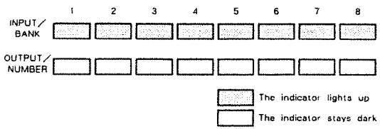
- When the check sum of the received Exclusive messages is incorrect, the indicators react as shown below:
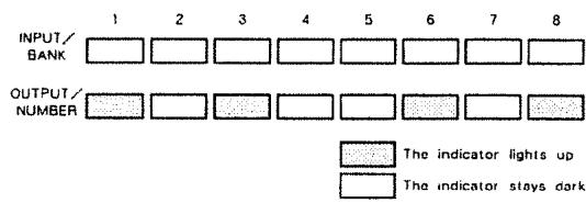
- If the indicators respond as shown below at power up, the battery for memory back-up is exhausted. Call your local Roland service center.
If the indicators respond as shown below at power up, data in memory may be lost.
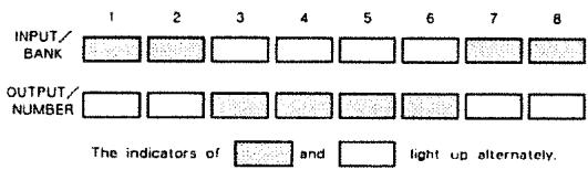
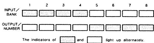
■ Initialization
A-880 can be initialized (returned to the manufacturer's preprogramed condition) by turning it on while holding the Signal Button and the Memory Button down. The indicators react as shown below:
| Function ... | Transmitted | Recognized | Remarks | |
| Basic Channel | Default Changed | 1-16、OFF1-16、OFF | Memorized. | |
| Mode | DefaultMessagesAltered | ××* * * * * * * | OMNI OFF×× | |
| NoteNumber | True Voice | ○*1 (69)********** | ×× | |
| Velocity | Note ONNote OFF | ○*1 (9n v = 64)○*1 (9n v = 0) | ×× | |
| After Touch | Key'sCh's | ×× | ×× | |
| Pitch Bender | × | × | ||
| Control Change | 0-120121 | ×*2 | ×× | |
| ProgChange True # | 0-630-63 | |||
| System Exclusive | ○ | ○ | ||
| System Common | Song PosSong SelTune | ××○ | ××× | |
| System Real Time | ClockCommands | ×× | ×× | |
| Aux Message | Local ON/OFFAll Notes OFFActive SenseReset | ×*2 (123)×× | ×○ (123 - 127)×× | |
| Notes | *1 In the TUNE MODE.*2 When the internal connection is cut off. | |||
Roland Exclusive Messages
1. Data Format for Exclusive Messages
Roland's MIDI implementation uses the following data format for all exclusive messages (type IV):
| Byte | Description |
| F0H | Exclusive status |
| 41H | Manufacturer ID (Roland) |
| DEV | Device ID |
| MDL | Model ID |
| CMD | Command ID |
| [BODY] | Main data |
| F7H | End of exclusive |
MIDI status: F0H, F7H
An exclusive message must be flanked by a pair of status codes, starting with a Manufacturer-ID immediately after FOH (MID version 1.0).
Manufacturer ID: 41H
The Manufacturer-II) identifies the manufacturer of a MIDI instrument that triggers an exclusive message. Value 411 represents Roland's Manufacturer-II.
Device-ID:DEV
The Device-II) contains a unique value that identifies the individual device in the multiple implementation of MIDI instruments. It is usually set to 0011 0FH ,a value smaller by one than that of a basic channel, but value 0011 1F11 may be used for a device with multiple basic channels.
Model-ID:MDL
The Model- ID contains a value that uniquely identifies one model from another. Different models, however, may share an identical Model- ID if they handle similar data.
The Model-II) format may contain 0011 in one or more places to provide an extended data field. The following are examples of valid Model-IDs, each representing a unique model:
0111
021
03H
00H 01H
0011.021
00H.00H.01H
Command-ID:CMD
The Command-ID indicates the function of an exclusive message. The Command-ID format may contain 00H in one or more places to provide an extended data field. The following are examples of valid Command-IDs, each representing a unique function:
011
02H
0311
0011.0111
0011 0211
00H,00H,01H
Main data:BODY
This field contains a message to be exchanged across an interface. The exact data size and contents will vary with the Model-ID and Command-ID.
2. Address-- mapped Data Transfer
Address mapping is a technique for transferring messages conforming to the data format given in Section 1. It assigns a series of memory-resident records--waveform and tone data, switch status, and parameters, for example--to specific locations in a machine-dependent address space, thereby allowing access to data residing at the address a message specifies.
Address-mapped data transfer is therefore independent of models and data categories. This technique allows use of two different transfer procedures: one-way transfer and handshake transfer.
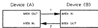
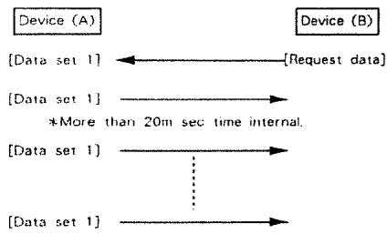
One way transfer procedure (See Section3 for details.)
This procedure is suited for the transfer of a small amount of data. It sends out an exclusive message completely independent of a receiving device status.
Connection Diagram
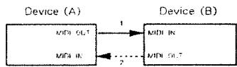
Connectional point2 is essential for "Request data" procedures, (See Section3.)
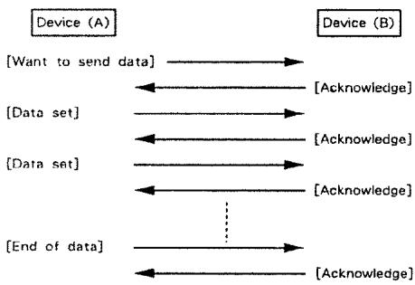
Handshake transfer procedure (See Section4 for details.)
This procedure initiates a predetermined transfer sequence (handshaking) across the interface before data transfer takes place. Handshaking ensures that reliability and transfer speed are high enough to handle a large amount of data.
Connection Diagram
Connectionat points1 and 2 is essential.
Notes on the above two procedures
There are separate Command-IDs for different transfer procedures.
DevicesA and B cannot exchange data unless they use the same transfer procedure, share identical Device-ID and Model ID, and are ready for communication.
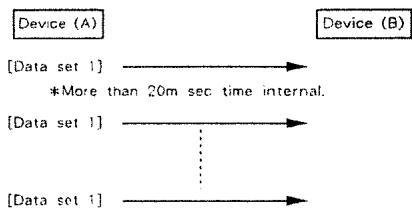
3. One-way Transfer Procedure
This procedure sends out data all the way until it stops when the messages are so short that answerbacks need not be checked.
For long messages, however, the receiving device must acquire each message in time with the transfer sequence, which inserts intervals of at least 20 milliseconds in between.
Types of Messages
| Message | Command ID |
| Request data 1 | RQ1 (11H) |
| Data set 1 | DT1 (12H) |
# Request data # 1: RQ1 (11H)
This message is sent out when there is a need to acquire data from a device at the other end of the interface. It contains data for the address and size that specify designation and length, respectively, of data required.
On receiving an RQI message, the remote device checks its memory for the data address and size that satisfy the request.
If it finds them and is ready for communication, the device will transmit a "Data set 1 (DT1)" message, which contains the requested data. Otherwise, the device will send out nothing.
| Byte | Description |
| F0H | Exclusive status |
| 41H | Manufacturer ID (Roland) |
| DEV | Device ID |
| MDL | Model ID |
| 11H | Command ID |
| aaH | Address MSB |
| LSB | |
| sGH | Size MSB |
| LSB | |
| sum | Check sum |
| F7H | End of exclusive |
The size of the requested data does not indicate the number of bytes that will make up a DT1 message, but represents the address fields where the requested data resides.
Some models are subject to limitations in data format used for a single transaction. Requested data, for example, may have a limit in length or must be divided into predetermined address fields before it is exchanged across the interface.
The same number of bytes comprises address and size data, which, however, vary with the Model-ID.
The error checking process uses a checksum that provides a bit pattern where the least significant 7 bits are zero when values for an address, size, and that checksum are summed.
Data set 1:DT1(12H)
This message corresponds to the actual data transfer process, Because every byte in the data is assigned a unique address, a DT1 message can convey the starting address of one or more data as well as a series of data formatted in an address dependent order.
The MIDI standards inhibit non-real time messages from interrupting an exclusive one. This fact is inconvenient for the devices that support a "soft-through" mechanism. To maintain compatibility with such devices, Roland has limited the DT1 to 256 bytes so that an excessively long message is sent out in separate segments.
| Byte | Description |
| FOH | Exclusive |
| 41H | Manufacturer ID (Roland) |
| DEV | Device ID |
| MDL | Model ID |
| 12H | Command ID |
| aaH | Address MSB |
| LSB | |
| ddH | Data |
| Check sum | |
| F7H | End of exclusive |
*A DT1 message is capable of providing only the valid data among those specified by an RQ1 message.
Some models are subject to limitations in data format used for a single transaction. Requested data, for example, may have a limit in length or must be divided into predetermined address fields before it is exchanged across the interface.
The number of bytes comprising address data varies from one Model-ID to another.
*The error checking process uses a checksum that provides a bit pattern where the least significant 7 bits are zero when values for an address, size, and that checksum are summed.
Example of Message Transactions
Device A sending data to Device B Transfer of a DT1 message is all that takes place.
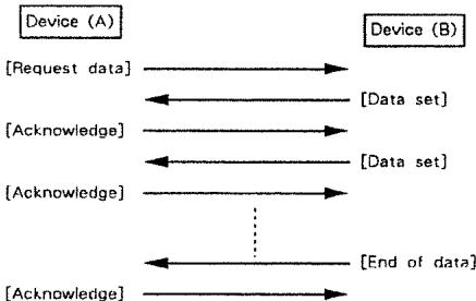
Device B requesting data from Device A
Device B sends an RQI message to Device A. Checking the message, Device A sends a DT1 message back to Device B.
4. Handshake- Transfer Procedure
Ilandshaking is an interactive process where two devices exchange error checking signals before a message transaction takes place, thereby increasing data reliability. Unlike one-way transfer that inserts a pause between message transactions, handshake transfer allows much speedier transactions because data transfer starts once the receiving device returns a ready signal.
When it comes to handling large amounts of data-- sampler waveforms and synthesizer tones over the entire range, for example-- across a MIDI interface, handshaking transfer is more efficient than one-way transfer.
Types of Messages
| Message | Command ID |
| Want to send data | WSD (40H) |
| Request data | ROD (41H) |
| Data set | DAT (42H) |
| Acknowledge | ACK (43H) |
| End of data | EOD (45H) |
| Communication error | ERR (4EH) |
| Rejection | RJC (4FH) |
Want to send data: WSD (40H)
This message is sent out when data must be sent to a device at the other end of the interface. It contains data for the address and size that specify designation and length, respectively, of the data to be sent.
On receiving a WSI) message, the remote device checks its memory for the specified data address and size which will satisfy the request. If it finds them and is ready for communication, the device will return an "Acknowledge (ACK)" message.
Otherwise, it will return a "Rejection (RJC)" message.
| Byte | Description |
| FOH | Exclusive status |
| 41H | Manufacturer ID (Roland) |
| DEV | Device ID |
| MDL | Model ID |
| 40H | Command ID |
| aaH | Address MSB |
| LSB | |
| ssH | Size MSB |
| sum | Check sum |
| F7H | End of exclusive |
- The size of the data to be sent does not indicate the number of bytes that make up a "Data set (DAT)" message, but represents the address fields where the data should reside.
Some models are subject to limitations in data format used for a single transaction. Requested data, for example, may have a limit in length or must be divided into predetermined address fields before it is exchanged across the interface.
The same number of bytes comprises address and size data, which, however, vary with the Model-Ib.
*The error checking process uses a checksum that provides a bit pattern where the least significant 7 bits are zero when values for an address, size, and that checksum are summed.
Request data: RQD (41H)
This message is sent out when there is a need to acquire data from a device at the other end of the interface. It contains data for the address and size that specify designation and length, respectively, of data required.
On receiving an RQD message, the remote device checks its memory for the data address and size which satisfy the request. If it finds them and is ready for communication, the device will transmit a "Data set (DAT)" message, which contains the requested data. Otherwise, it will return a "Rejection (RJC)" message.
| Byte | Description |
| FOH | Exclusive status |
| 41H | Manufacturer ID (Roland) |
| DEV | Device ID |
| MDL | Model ID |
| 41H | Command ID |
| aaH | Address MSB |
| LSB | |
| ssH | Size MSB |
| LSB | |
| sum | Check sum |
| F7H | End of exclusive |
The size of the requested data does not indicate the number of bytes that make up a "Data set (DAT)" message, but represents the address fields where the requested data resides.
Some models are subject to limitations in data format used for a single transaction. Requested data, for example, may have a limit in length or must be divided into predetermined address fields before it is exchanged across the interface.
The same number of bytes comprises address and size data, which, however, vary with the Model-ID.
The error checking process uses a checksum that provides a bit pattern where the least significant 7 bits are zero when values for an address, size, and that checksum are summed.
# Data set: DAT (42H)
This message corresponds to the actual data transfer process. Because every byte in the data is assigned a unique address, the message can convey the starting address of one or more data as well as a series of data formatted in an address-dependent order.
Although the MLDI standards inhibit non-real time messages from interrupting an exclusive one, some devices support a "soft-through" mechanism for such interrupts. To maintain compatibility with such devices, Roland has limited the DAT to 256bytes so that an excessively long message is sent out in separable segments.
| Byte | Description |
| FOH | Exclusive status |
| 41H | Manufacturer ID (Roland) |
| DEV | Device ID |
| MDL | Model ID |
| 42H | Command ID |
| aah | Address MSB |
| : | : |
| : | : |
| : | LSR |
| ddH | Data |
| : | : |
| : | : |
| sum | Check sum |
| F7H | End of exclusive |
*A DAT message is capable of providing only the valid data among those specified by an RQI or WSI) message.
Some models are subject to limitations in data format used for a single transaction. Requested data, for example, may have a limit in length or must be divided into predetermined address fields before it is exchanged across the interface.
The number of bytes comprising address data varies from one model ID to another.
*The error checking process uses a checksum that provides a bit pattern where the least significant 7 bits are zero, which values for an address, size, and that checksum are summed.
Acknowledgement: ACK (43H)
This message is sent out when no error was detected on reception of a WSD, DAT, "End of data (FOD)", or some other message and a requested setup or action is complete. Unless it receives an ACK message, the device at the other end will not proceed to the next operation.
| Byte | Description |
| F0H | Exclusive status |
| 41H | Manufacturer ID (Roland) |
| DEV | Device ID |
| MDL | Model ID |
| 43H | Command ID |
| F7H | End of exclusive |
End of data: EOD (45H)
This message is sent out to inform a remote device of the end of a message. Communication, however, will not come to an end unless the remote device returns an ACK message even though an EOD message was transmitted.
| Byte | Description |
| F0H | Exclusive status |
| 41H | Manufacturer ID (Roland) |
| DEV | Device ID |
| MDL | Model ID |
| 45H | Command ID |
| F7H | End of exclusive |
Communications error: ERR (4EH)
This message warns the remote device of a communications fault encountered during message transmission due, for example, to a checksum error. An ERR message may be replaced with a "Rejection (RJC)" one, which terminates the current message transaction in midstream.
When it receives an ERR message, the sending device may either attempt to send out the last message a second time or terminate communication by sending out an RJC message.
| Byte | Description |
| FOH | Exclusive status |
| 41H | Manufacturer ID (Roland) |
| DEV | Device ID |
| MDL | Model ID |
| 4EH | Command ID |
| F7H | End of exclusive |
Rejection: RJC (4FH)
This message is sent out when there is a need to terminate communication by overriding the current message. An RJC message will be triggered when:
- a WSD or RQD message has specified an illegal data address or size.
- the device is not ready for communication.
- an illegal number of addresses or data has been detected.
data transfer has been terminated by an operator. - a communications error has occurred.
An ERR message may be sent out by a device on either side of the interface. Communication must be terminated immediately when either side triggers an ERR message.
| Byte | Description |
| FOH | Exclusive status |
| 41H | Manufacturer ID (Roland) |
| DEV | Device ID |
| MDL | Model ID |
| 4FH | Command ID |
| F7H | End of exclusive |
Example of Message Transactions
Data transfer from device (A) to device (B).
Device (A) requests and receives data from device (B)
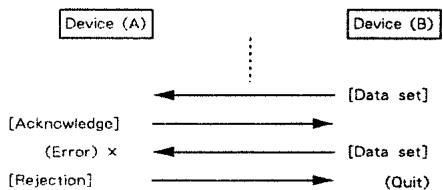
- Error occurs while device (A) is receiving data from device (B).
1) Data transfer from device (A) to device (B).
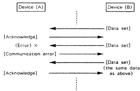
2) Device (B) rejects the data re-transmitted, and quits data transfer.

3) Device (A) immediately quits data transfer.
1. TRANSMITTED DATA
1.1 Bypassed message
1.1.1 As connected in an ordinary way
All received messages are sent out from MDI OUT.
1.1.2 Messages mixed by MIXER and sent out from MiDI OUT.
The following MIDI IN messages are sent to MIDI OUT if they are received from Mixed MIDs and corresponding MIDIMESSAGE THRU SW is on as
- Channel messages.
System Common messages except System Exclusive message of A-B80 received from certain MDi IN(Control MDi IN).
System Realtime messages received from master MIDl IN exceptFE(active sensing) andFF (Reset).
1.2 Message which is created and sent out from MIDI OUT.
1.2.1 Message to be sent out from the disconnected MIDI OUT as the internal connection is cut off.
Reset all controllers
Status BnH
Second 79H
Third 00H
nH:MIDI channel OH- Fh (0-15)
All notes off
Status BnH
Second 7BH
Third 00H
nH:MID1 channel OH-Fh (0-15)
1.2.2 Created message in TUNE MODE
Tune request
Status
F6H
A-880 sends the message when into the TUNE MODE.
Reset all controllers
Status BnH
Second 79H
Third 00H
nH:MIDI channel OH-Fh0-15
*A - 880 sends the message when into the TUNE MODE.
Note on
Status 9nH
Second 45H
Third G4H
nH:MIDI channel OH-Fh (0-15)
A-880 sends the message for all channels in the TUNE MODE at regular interval.
Note off
Status 9nH
Second 45H
Third 00H
nH:MIDI channel OH-Fh (0-15)
A-880 sends the message for all channels in the TUNE MODE at regular interval.
All notes off
Status BnH
Second 78H
Third 00H
nH:MDI channel OH-Fh (0-15)
# A - 880 sends this when out from the TUNE MODE.
1.2.3 Created message by MIDIMESSAGE MIXER
All notes off
Status BrtH
Second 7BH
Third OCH
nH:MIDI channel OH-Fh (0-15)
All notes of each channel are offered with both of "All notes off SW" and "Retrigger Sw" are on.
1.2.4 System exclusive message
Status
FOH :SystemExclusive
:EOX(End of System Exclusive)
*Transmitted to the MID: OUT assigned as MIX Output.
See "3. EXCLUSIVE COMMUNICATIONS" for details.
2. RECOGNIZED DATA
Recognized if the following data is received from certain MIDI iN(Control MIDI iN).
2.1 Program change
Status
CnH
Second
pH
ppH : Program number
OH-3FH(0-63)
nH : MIDI channel
OH - Fh (0 - 15)
*A-880 changes its internal connection on receiving this message.
2.2 System exclusive
Status
FOH
:System Exclusive
F7H
:EOX(End of System Exclusive)
See "3. EXCLUSIVE COMMUNICATIONS" for details.
3. EXCLUSIVE COMMUNICATIONS
Model-1D# of A-880 is 20H.
Device-1D# is the program channel#.
3.1 One way communication
3.1.1 Request
RQ1 11H
When the ROI received contains addresses listed in "4. Address mapping of parameters".
and address size is 1 or more.
A-880 sends the corresponding data.
A-880 won't transmit ROI by itself.
Byte
FOH
Description
41H
Poland - ID
DEV
Device - ID
20H
Model-1D(A-BBD)
118
Command - ID (R01)
aah
Address
ssH
Size
sum
Checksum
FTH
EOX (End of Exclusive)
3.1.2 Data set
DT1 12H
When the DT1 received contains addresses listed in "4. Address mapping of parameters". A-
880 stores the data into that memory location.
A-880 sends this message upon receiving RQ1.
Byte
FOH
Description
41H
Poland - ID
DEV
Device - ID
20H
Model - ID (A-880)
12H
Command - ID (D11)
aah
Address
ddH
Data
:
sum
F7H
Checksum
EOX (End of Exclusive)
4. Address mapping of parameters
Addresses are shown in Hexadecimal, while numbers are given in 7 bits.
| Address | |
| binary | 0aaa aaaa |
| 7 bit Hex | AA |
| address | Description | |
| 00H | 0000 aaaa | Mixed MIDI IN # 0-7:1-8 Master 8-15:1-8 Slave |
| 01H | 0000 aaaa | Connection of MIDI OUT # 1 0:No connection 1-8:MIDI IN # 3: Mixed MIDI INs |
| 02H | 0000 aaaa | Connection of MIDI OUT # 2 : |
| 0BH | 0000 aaaa | Connection of MIDI OUT # 8 |
| Total size | 09H | |
SPECIFICATIONS
Indicators
Input/Bank Indicator × 8
Output/Number Indicator x 8
Signal Indicator
Scan/Mix Indicator
Memory Indicator
Write Indicator
- Buttons
Input/Bank Button x 8
Output/Number Button x 8
Signal Button
Scan/Mix Button
Memory Button
Write Button
- Sockets
MIDI IN x 8
MIDI OUT × 8
Dimensions
482(W) x 44(H) x 286(D) mm
19" x 1-3/4" x 11-11/16"
Weight
3kg/6lb10oz
Power Consumption
5W