
KAC-5204 - Amplificateur de voiture KENWOOD - Notice d'utilisation et mode d'emploi gratuit
Retrouvez gratuitement la notice de l'appareil KAC-5204 KENWOOD au format PDF.

| Type de produit | Amplificateur de puissance |
| Caractéristiques techniques principales | 4 canaux, 50 W par canal à 4 ohms |
| Alimentation électrique | 12 V DC |
| Dimensions approximatives | 300 x 220 x 60 mm |
| Poids | 2,5 kg |
| Compatibilités | Compatible avec la plupart des systèmes audio de voiture |
| Fonctions principales | Amplification audio, réglage des basses et des aigus |
| Entretien et nettoyage | Essuyer avec un chiffon doux, éviter l'humidité |
| Pièces détachées et réparabilité | Réparabilité limitée, pièces disponibles sur demande |
| Sécurité | Ne pas exposer à l'eau, respecter les limites de puissance |
| Informations générales utiles | Idéal pour améliorer la qualité sonore des véhicules, installation recommandée par un professionnel |
FOIRE AUX QUESTIONS - KAC-5204 KENWOOD
Questions des utilisateurs sur KAC-5204 KENWOOD
0 question sur cet appareil. Repondez a celles que vous connaissez ou posez la votre.
Poser une nouvelle question sur cet appareil
Téléchargez la notice de votre Amplificateur de voiture au format PDF gratuitement ! Retrouvez votre notice KAC-5204 - KENWOOD et reprennez votre appareil électronique en main. Sur cette page sont publiés tous les documents nécessaires à l'utilisation de votre appareil KAC-5204 de la marque KENWOOD.
MODE D'EMPLOI KAC-5204 KENWOOD
KENWOOD
KAC-5204
STEREO/BRIDGEABLE POWER AMPLIFIER ▶ page 2-11
INSTRUCTION MANUAL
AMPLIFICATEUR DE PUISSANCE STEREO/COMPATIBLE ▶ page 12-21
MODE D'EMPLOI
ESTÉREO/AMPLIFICADOR DE POTENCIA CONECTABLE ▶ página 22-31
MANUAL DE INSTRUCCIONES
Kenwood Corporation

AE86
Take the time to read through this instruction manual.
Familiarity with installation and operation procedures will help you obtain the best performance from your new power amplifier.
For your records
Record the serial number, found on the back of the unit, in the spaces designated on the warranty card, and in the space provided below. Refer to the model and serial numbers whenever you call upon your Kenwood dealer for information or service on the product.
Model KAC-5204 Serial number ____
US Residence Only
Register Online
Register your Kenwood product at
www.Kenwoodusa.com
WARNING
To prevent injury or fire, take the following precautions:
- When extending the ignition, battery, or ground wires, make sure to use automotive-grade wires or other wires with a 5mm^2 (AWG 10) or more to prevent wire deterioration and damage to the wire coating.
- To prevent a short circuit, never put or leave any metallic objects (such as coins or metal tools) inside the unit.
- If the unit starts to emit smoke or strange smells, turn off the power immediately and consult your Kenwood dealer.
- Do not touch the unit during use because the surface of the unit becomes hot and may cause burns if touched.
- Mounting and wiring this product requires skills and experience. For safety's sake, leave the mounting and wiring work to professionals.
CAUTION
To prevent damage to the machine, take the following precautions:
- Be sure the unit is connected to a 12V DC power supply with a negative ground connection.
- Do not open the top or bottom covers of the unit.
- Do not install the unit in a spot exposed to direct sunlight or excessive heat or humidity. Also avoid places with too much dust or the possibility of water splashing.
- When replacing a fuse, only use a new one with the prescribed rating. Using a fuse with the wrong rating may cause your unit to malfunction.
- To prevent a short circuit when replacing a fuse, first disconnect the wiring harness.
NOTE
- If you experience problems during installation, consult your Kenwood dealer.
- If the unit does not seem to be working right, consult your Kenwood dealer.
FCC WARNING
This equipment may generate or use radio frequency energy. Changes or modifications to this equipment may cause harmful interference unless the modifications are expressly approved in the instruction manual. The user could lose the authority to operate this equipment if an unauthorized change or modification is made.
FCC NOTE
This equipment has been tested and found to comply with the limits for a Class B digital device, pursuant to Part 15 of the FCC Rules. These limits are designed to provide reasonable protection against harmful interference in a residential installation. This equipment may cause harmful interference to radio communications, if it is not installed and used in accordance with the instructions. However, there is no guarantee that interference will not occur in a particular installation. If this equipment does cause harmful interference to radio or television reception, which can be determined by turning the equipment off and on, the user is encouraged to try to correct the interference by one or more of the following measures:
- Reorient or relocate the receiving antenna.
- Increase the separation between the equipment and receiver.
- Connect the equipment into an outlet on a circuit different from that to which the receiver is connected.
- Consult the dealer or an experienced radio/TV technician for help.
NOTE
This Class B digital apparatus complies with Canadian ICES-003.

Declaration of Conformity with regard to the EMC Directive 2004/108/EC
Manufacturer:
Kenwood Corporation
2967-3 Ishikawa-machi, Hachioji-shi, Tokyo,
192-8525 Japan
EU Representative's:
Kenwood Electronics Europe BV
Amsterdamseweg 37, 1422 AC UITHOORN,
The Netherlands
Information on Disposal of Old Electrical and Electronic Equipment (applicable for EU countries that have adopted separate waste collection systems)

Products with the symbol (crossed-out wheeled bin) cannot be disposed as household waste.
Old electrical and electronic equipment should be recycled at a facility capable of handling these items and their waste byproducts. Contact your local authority for details in locating a recycle facility nearest to you. Proper recycling and waste disposal will help conserve resources whilst preventing detrimental effects on our health and the environment.
This Product is not installed by the manufacturer of a vehicle on the production line, nor by the professional importer of a vehicle into an EU Member State.
Cleaning the unit
If the front panel gets dirty, turn off the power and wipe the panel with a dry silicon cloth or soft cloth.
CAUTION
Do not wipe the panel with a hard cloth or a cloth dampened by volatile solvents such as paint thinner and alcohol. They can scratch the surface of the panel and/or cause the indicator letters to peel off.
To prevent battery rise
When the unit is used in the ACC ON position without turning the engine ON, it depletes the battery. Use it after starting the engine.
Protection function
There is a Protection function installed in the unit to protect the unit and speakers from various problems. When Protection operates, the indicator informs you of the condition. (Refer to page 5)
Accessories
| Part name | External View | Number of Items |
| Self-tapping screws (ø4 × 16 mm) |  | 4 |
| Terminal cover (Power terminal) |  | 1 |
| Speaker level input cable |  | 1 |
■ Wiring
- Take the battery wire for this unit directly from the battery. If it's connected to the vehicle's wiring harness, it can cause blown fuses etc.
- If a buzzing noise is heard from the speakers when the engine is running, connect a line noise filter (optional) to each of the battery wire.
- Do not allow the wire to directly contact the edge of the iron plate by using Grommets.
- Connect the ground wire to a metal part of the car chassis that acts as an electrical ground passing electricity to the battery's negative terminal. Do not turn the power on if the ground wire is not connected.
- Be sure to install a protective fuse in the power cord near the battery. The protective fuse should be the same capacity as the unit's fuse capacity or somewhat larger.
- For the power cord and ground, use a vehicle type (fireproof) power wiring cord with a current capacity greater than the unit's fuse capacity. (Use a power wiring cord with a diameter of 5mm^2 (AWG 10) or greater.)
- When more than one power amplifier are going to be used, use a power supply wiring wire and protective fuse of greater current-handling capacity than the total maximum current drawn by each amplifier.
■ Speaker Selection
- The rated input power of the speakers that are going to be connected should be greater than the maximum output power (in Watts) of the amplifier. Use of speakers having input power ratings that are less than the output power of the amplifier will cause smoke to be emitted as well as damage.
- The impedance of the speakers that are going to be connected should be 2 or greater (for stereo connections), or 4 or greater (for bridged connections). When more than one set of speakers are going to be used, calculate the combined impedance of the speakers and then connect suitable speakers to the amplifier.
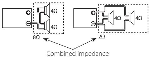
text_image
8Ω 4Ω 4Ω 2Ω Combined impedance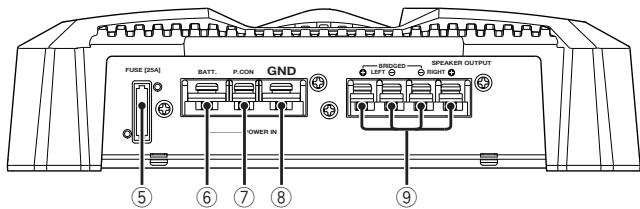
text_image
FUSE [25A] BATT. P.CON GND SINJOGO LETT SPEAKER OUTPUT RIGHT ① POWER IN ⑤ ⑥ ⑦ ⑧ ⑨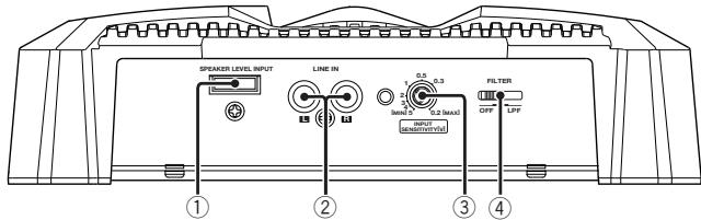
text_image
SPEAKER LEVEL INPUT LINE IN 0.5 0.3 SMAD 0.2 SMAD FILTER OFF LPF ① ② ③ ④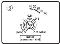
text_image
③ 40 30 20 10 (W) 0.5 0.3 1 2 3 4 [MIN] 5 0.2 [MAX] INPUT SENSITIVITY[V]① Speaker level input terminals
NOTE
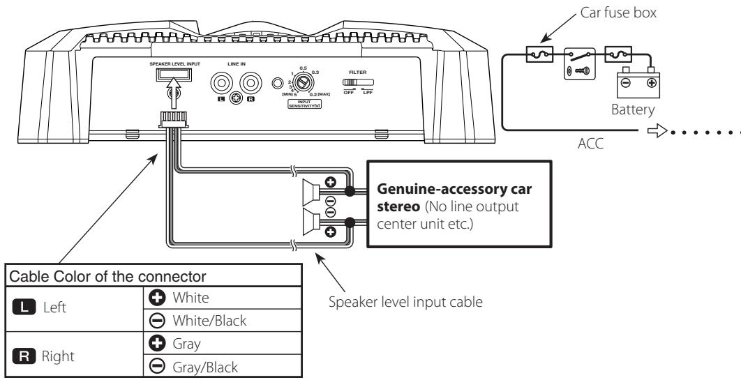
- The genuine-accessory car stereo shall have a maximum power output of no more than 40 W.
- Do not connect the speaker output leads from a power amplifier (Optional) to the speaker level input terminals of this unit, for this may cause malfunction or damage.
- Do not connect cables and leads to both RCA cable input jacks and the speaker level input terminals simultaneously, for this may cause malfunction or damage.
- Connect the power control lead to a power supply which can be turned ON/OFF by the ignition key switch (ACC line). With this connection, shock noise may be generated when the power of the genuine-accessory car stereo is switched ON/OFF.
② LINE IN terminal
③ INPUT SENSITIVITY control
Set this control according to the pre-output level of the center unit connected with this unit, or to the maximum power output of the genuine-accessory car stereo.
Use the diagram on the right as a guide.
NOTE
For the pre-output level or the maximum power output, refer to the
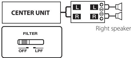
④ FILTER switch
This switch allow filtering of the speaker output signals.
- OFF position:
The original sound without filtering is output.
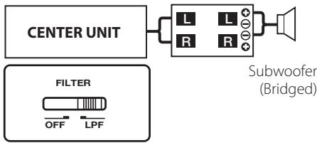
• LPF (Low Pass Filter) position:
Only frequencies of 80 Hz or lower are output. (Frequencies above 80 Hz are cut.) The speaker output is automatically switched to monaural (L+R).
⑤ Fuse (25 A)
⑥ Battery terminal
⑦ Power control terminal
Controls the unit ON/OFF.
NOTE
Controls the unit power. Be sure to connect it with all the systems.
⑧ Ground terminal
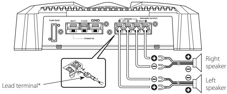
⑨ Speaker output terminals
- Stereo Connections:
When you wish to use the unit as a stereo amplifier, stereo connections are used. The speakers to be connected should have an impedance of 2 or greater. When multiple speakers are to be connected, ensure that the combined impedance is 2 or greater for each channel.
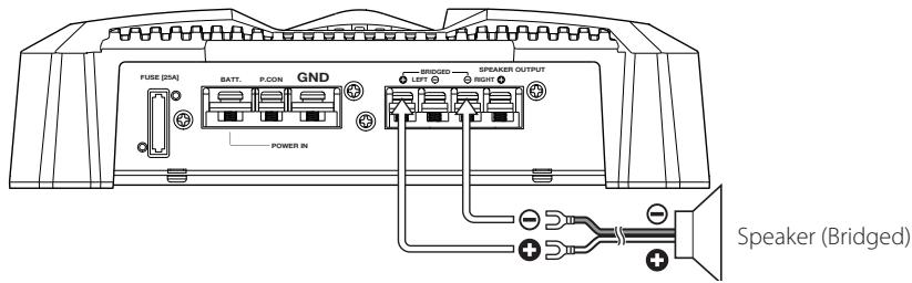
• Bridged Connections:
When you wish to use the unit as a high-output monaural amplifier, bridged connections are used. (Make connections to the LEFT channel ⊕ and the RIGHT channel ⊖ SPEAKER OUTPUT terminals.)
The speakers to be connected should have an impedance of 4 or greater. When multiple speakers are to be connected, ensure that the combined impedance is 4 or greater.
natural_image
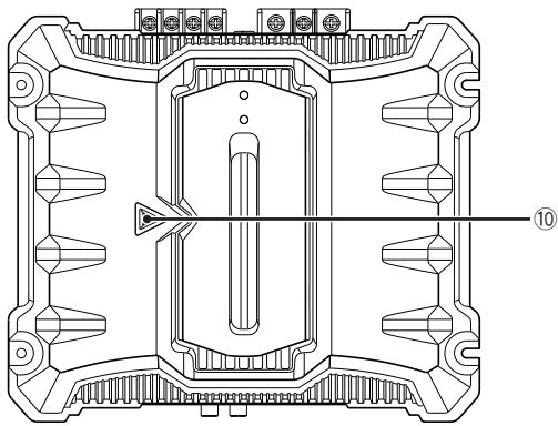
Technical line drawing of a mechanical component with symmetrical slots and a central slot, no text or symbols present.⑩ Power indicator
When the power is turned on, the Power indicator lights.
If the Power indicator does not light when the power is turned on, the protection function may be activated. Check whether there is any indication of trouble.
■ The protection function is activated in the following situations:
This unit is equipped with a protection function for protecting this unit and your speakers from various accidents or problems that can occur. When the protection function is triggered, the Power indicator goes off and the amplifier stops operating.
- When a speaker wire may be short-circuited.
- When a speaker output contacts ground.
- When the unit malfunctions and a DC signal is sent to the speaker output.
- When the internal temperature is high and unit won't operate.
- When a ground wire of the center unit (cassette receiver, CD receiver, etc.) or this unit is not connected to a metal part serving as an electrical ground passing electricity to the battery's negative terminal.
■ System examples
• 2-channel system:
Left speaker
text_image
CENTER UNIT L L R R Right speaker FILTER OFF LPF- Subwoofer system:
text_image
CENTER UNIT FILTER OFF LPF Subwoofer (Bridged)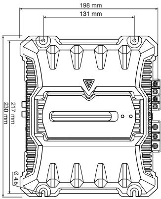
text_image
198 mm 131 mm 217 mm 240 mm Ø46CAUTION
- Do not install in the below locations; (Unstable location, In a location that interferes with driving, In a location that gets wet, In a dusty location, In a place that gets hot, In a place that gets direct sunlight, In a location that gets hit by hot air)
- Do not install the unit under the carpet.
Otherwise heat build-up occurs and the unit may be damaged. - Install this unit in a location which allows heat to easily dissipate.
Once installed, do not place any object on top of the unit. - The surface temperature of the amplifier will become hot during use. Install the amplifier in a place where people, resins, and other substances that are sensitive to heat will not come into contact with it.
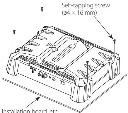
text_image
Self-tapping screw (ø4 x 16 mm) Installation board, etc.Installation board, etc.
(thickness: 15 mm or more)
- When making a hole under a seat, inside the trunk, or somewhere else in the vehicle, check that there is nothing hazardous on the opposite side such as a gasoline tank, brake pipe, or wiring harness, and be careful not to cause scratches or other damage.
- Do not install near the dashboard, rear tray, or air bag safety parts.
- The installation to the vehicle should securely fasten the unit to a place in which it will not obstruct driving. If the unit comes off due to a shock and hits a person or safety part, it may cause injury or an accident.
• After installing the unit, check to make sure that electrical equipment such as the brake lamps, turn signal lamps and windshield wipers operate normally.

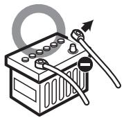
WARNING
Remove the ignition key and disconnect the negative ⊖ terminal of the battery to prevent short circuits.
natural_image
Illustration of a battery with a switch and a ring, no text or symbols present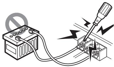
natural_image
Pure electrical circuit lines without any symbols■ Installation procedure
Since there are large variety of settings and connections possible according to applications, read the instruction manual well to select the proper setting and connection.
- Remove the ignition key and disconnect the negative terminal of the battery to prevent short circuits.
- Set the unit according to the intended usage.
- Connect the input and output wires of the units.
- Connect the speaker wires.
- Connect the power wire, power control wire and grounding wire following this order.
- Install the unit in the car.
- Connect the negative terminal of the battery.
CAUTION
- If sound is not output normally, immediately turn power off and check connections.
- Be sure to turn the power off before changing the setting of any switch.
- If the fuse blows, check wires for shorts, then replace the fuse with one of the same rating.
- Check that no unconnected wires or connectors are touching the car body. Do not remove caps from unconnected wires or connectors to prevent short circuits.
- Connect the speaker wires to appropriate speaker connectors separately. Sharing the negative wire of the speaker or grounding speaker wires to the metal body of the car can cause this unit to fail.
• After installation, check that the brake lamps, winkers, and wipers work properly.
■ RCA cable or Speaker level input connection
(RCA cable Connections)
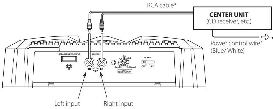
text_image
RCA cable* CENTER UNIT (CD receiver, etc.) Power control wire* (Blue/White) SPRAKER LEVEL INPUT LINE IN FILTER OFF LPF INPUT SENSIT(NYU) Left input Right input(Speaker level input Connections)
text_image
Speaker Level INPUT LINE IN 0.5 0.3 FILTER OFF LPF CAR fuse box Battery ACC Genuine-accessory car stereo (No line output center unit etc.) Speaker level input cable Cable Color of the connector L Left White White/Black R Right Gray Gray/Black■ Speaker wire connection
(Stereo Connections)
text_image
FUSE (25A) BATT. P.CON GND BRIDGE SPEAKER OUTPUT LEFT 0 RIGHT 0 POWER IN Lead terminal* Right speaker Left speaker(Bridged Connections)
text_image
FUSE (25A) BATT P-CON GND POWER IN BRIDGED LEFT SPEAKER OUTPUT RICHEN Speaker (Bridged)■ Power wire connection

text_image
FUSE (2x1) BATT. P/CON GND SROCCED SPEAKER OUTPUT RIGHT POWER III Terminal cover Power control wire* Battery wire* Ground wire* Lead terminal* Protective Fuse* BatteryWhat might appear to be a malfunction in your unit may just be the result of slight misoperation or miswiring. Before calling service, first check the following table for possible problems.
| PROBLEM | POSSIBLE CAUSE | SOLUTION |
| No sound.(No sound from one side.)(Blown fuse.) | Input (or output) cables are disconnected.Protection circuit may be activated.Volume is too high.The speaker cord is shorted. | Connect the input (or output) cables.Check connections by referring to.<Protection function>.Replace the fuse and use lower volume.After check the speaker cord and fixing the cause of the short, replace the fuse. |
| The output level is too small (or too large). | The input sensitivity adjusting control is not set to the correct position. | Adjust the control correctly referring to<Controls>. |
| The sound quality is bad.(The sound is distorted.) | The speakers wire are connected with wrong / polarity.A speaker wire is pinched by a screw in the car body.The switches may be set improperly. | Connect them properly checking the / of the terminals and wires well.Connect the speaker wire again so that it is not pinched by anything.Set switches properly by referring to<System examples>. |
Specifications subject to change without notice.
CEA-2006
RMS Watts per channel @ 4 ohms, 1 % THD+N....60 W × 2
Signal to Noise Ratio (Reference: 1Watt into 4 ohms)....75 dBA

Audio Section
Max Power Output 350 W
Rated Power Output
Normal (4 Ω) (20 Hz – 20 kHz, 1.0 % THD)....60 W × 2
(4Ω) (DIN: 45324, +B = 14.4V) 60 W × 2
(2 Ω) (1 kHz, 1.0 % THD)....75 W × 2
Bridged(4 Ω) (1 kHz, 1.0 % THD)....150 W × 1
Frequency Response (+0, -3 dB) 5 Hz – 50 kHz
Sensitivity (rated output) (MAX.) 0.2 V
Sensitivity (rated output) (MIN.) 5.0 V
Signal to Noise Ratio....94 dB
Input Impedance....10 kΩ
Low Pass Filter Frequency (-12 dB/oct.) 80 Hz
General
Operating Voltage....14.4 V (11 - 16 V allowable)
Current Consumption 18 A
Dimensions (W × H × D)....198 × 59 × 230 mm
7-13/16×2-5/16×9-1/16 inch
Weight....1.7 kg (3.7 lbs)