
DTX522K/DTX542K - Batterie électronique YAMAHA - Notice d'utilisation et mode d'emploi gratuit
Retrouvez gratuitement la notice de l'appareil DTX522K/DTX542K YAMAHA au format PDF.
| Type de produit | Batterie électronique |
| Marque | YAMAHA |
| Modèle | DTX522K / DTX542K |
| Alimentation | Adaptateur secteur DC 12V (inclus) |
| Module de batterie | DTX502 avec multiples sons et fonctions |
| Pads inclus (DTX522K) | 1 pad caisse claire XP80, 3 pads toms TP70, 1 pad kick KP65, 1 pad hi-hat HH65, 3 pads cymbales (1x PCY135, 2x PCY100) |
| Pads inclus (DTX542K) | 1 pad caisse claire XP80, 3 pads toms XP70, 1 pad kick KP65, 1 pad hi-hat HH65, 3 pads cymbales (1x PCY135, 2x PCY100) |
| Support | Rack électronique RS502 |
| Fonctions principales | Pads sensibles à la vélocité, cymbales avec zones multiples, module avec sons intégrés, connectivité MIDI, métronome, fonction d'enregistrement |
| Sécurité | Ne pas démonter ni modifier l'appareil ; utiliser sur une surface stable ; éviter de faire trébucher sur les câbles ; ne pas s'asseoir ou se tenir debout sur le rack |
| Entretien et nettoyage | Dépoussiérer avec un chiffon doux sec ; pour les taches, utiliser un chiffon humide avec un détergent neutre puis essuyer avec un chiffon humide et bien essoré ; ne pas utiliser de solvants |
| Pièces détachées et réparabilité | Pads, rack, câbles, adaptateur et pied de hi-hat disponibles auprès de revendeurs Yamaha ; réparation par un technicien agréé |
| Informations générales | Notice d'assemblage incluse ; nécessite assemblage du rack RS502 avant montage des pads ; tapis de sol recommandé (vendu séparément) |
FOIRE AUX QUESTIONS - DTX522K/DTX542K YAMAHA
Questions des utilisateurs sur DTX522K/DTX542K YAMAHA
0 question sur cet appareil. Repondez a celles que vous connaissez ou posez la votre.
Poser une nouvelle question sur cet appareil
Téléchargez la notice de votre Batterie électronique au format PDF gratuitement ! Retrouvez votre notice DTX522K/DTX542K - YAMAHA et reprennez votre appareil électronique en main. Sur cette page sont publiés tous les documents nécessaires à l'utilisation de votre appareil DTX522K/DTX542K de la marque YAMAHA.
MODE D'EMPLOI DTX522K/DTX542K YAMAHA
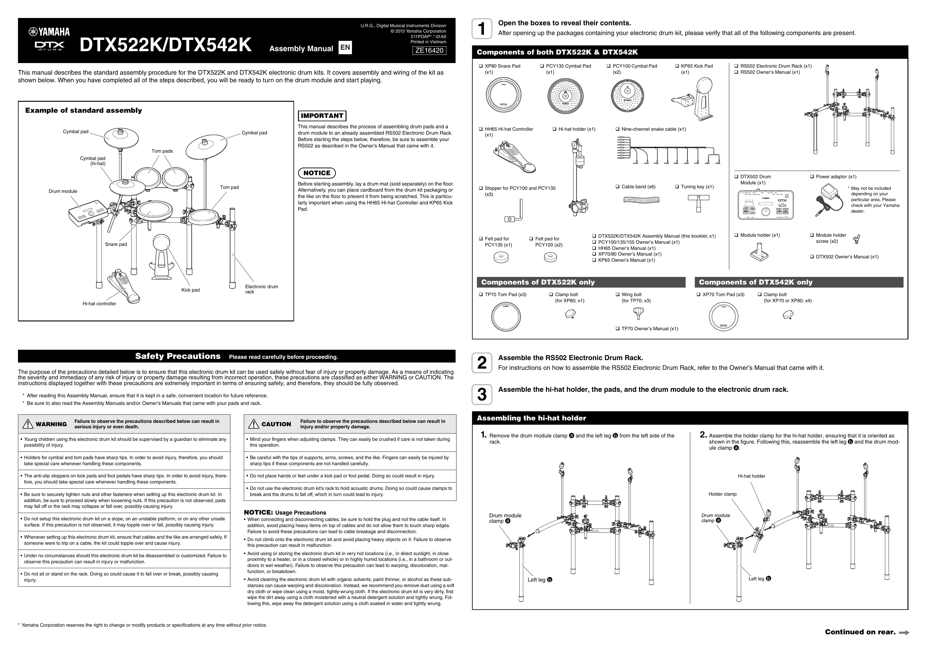
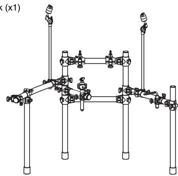
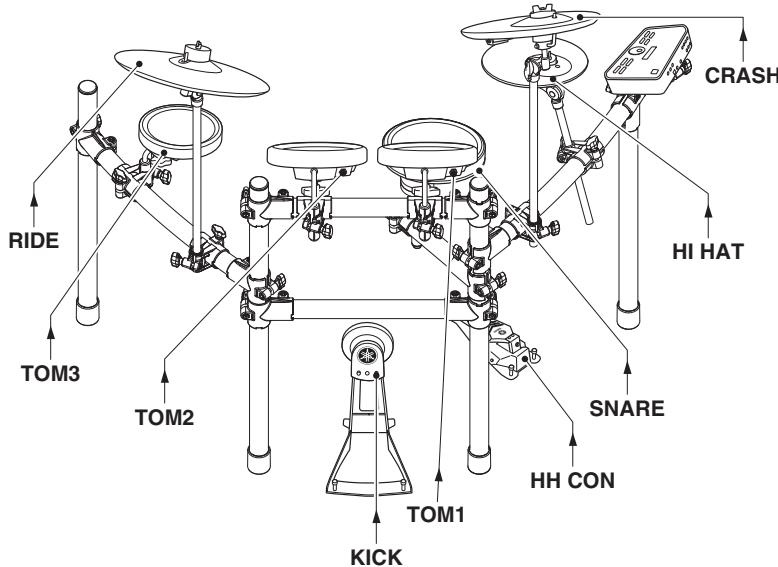
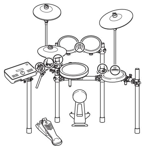
This manual describes the standard assembly procedure for the DTX522K and DTX542K electronic drum kits. It covers assembly and wiring of the kit as shown below. When you have completed all of the steps described, you will be ready to turn on the drum module and start playing.
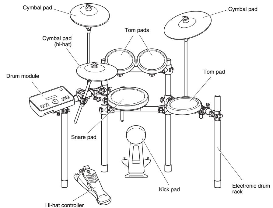
Example of standard assembly
IMPORTANT
This manual describes the process of assembling drum pads and a drum module to an already assembled RS502 Electronic Drum Rack. Before starting the steps below, therefore, be sure to assemble your RS502 as described in the Owner's Manual that came with it.
NOTICE
Before starting assembly, lay a drum mat (sold separately) on the floor. Alternatively, you can place cardboard from the drum kit packaging or the like on the floor to prevent it from being scratched. This is particularly important when using the HH65 Hi-hat Controller and KP65 Kick Pad.
Safety Precautions
Please read carefully before proceeding.
The purpose of the precautions detailed below is to ensure that this electronic drum kit can be used safely without fear of injury or property damage. As a means of indicating the severity and immediacy of any risk of injury or property damage resulting from incorrect operation, these precautions are classified as either WARNING or CAUTION. The instructions displayed together with these precautions are extremely important in terms of ensuring safety, and therefore, they should be fully observed.
- After reading this Assembly Manual, ensure that it is kept in a safe, convenient location for future reference.
- Be sure to also read the Assembly Manuals and/or Owner's Manuals that came with your pads and rack.

Failure to observe the precautions described below can result in serious injury or even death.
- Young children using this electronic drum kit should be supervised by a guardian to eliminate any possibility of injury.
- Holders for cymbal and tom pads have sharp tips. In order to avoid injury, therefore, you should take special care whenever handling these components.
- The anti-slip stoppers on kick pads and foot pedals have sharp tips. In order to avoid injury, therefore, you should take special care whenever handling these components.
- Be sure to securely tighten nuts and other fasteners when setting up this electronic drum kit. In addition, be sure to proceed slowly when loosening nuts. If this precaution is not observed, pads may fall off or the rack may collapse or fall over, possibly causing injury.
- Do not setup this electronic drum kit on a slope, on an unstable platform, or on any other unsafe surface. If this precaution is not observed, it may topple over or fall, possibly causing injury.
- Whenever setting up this electronic drum kit, ensure that cables and the like are arranged safely. If someone were to trip on a cable, the kit could topple over and cause injury.
- Under no circumstances should this electronic drum kit be disassembled or customized. Failure to observe this precaution can result in injury or malfunction.
- Do not sit or stand on the rack. Doing so could cause it to fall over or break, possibly causing injury.

CAUTION Failure to observe the precautions described below can result in injury and/or property damage.
- Mind your fingers when adjusting clamps. They can easily be crushed if care is not taken during this operation.
- Be careful with the tips of supports, arms, screws, and the like. Fingers can easily be injured by sharp tips if these components are not handled carefully.
- Do not place hands or feet under a kick pad or foot pedal. Doing so could result in injury.
- Do not use the electronic drum kit's rack to hold acoustic drums. Doing so could cause clamps to break and the drums to fall off, which in turn could lead to injury.
NOTICE: Usage Precautions
- When connecting and disconnecting cables, be sure to hold the plug and not the cable itself. In addition, avoid placing heavy items on top of cables and do not allow them to touch sharp edges. Failure to avoid these precautions can lead to cable breakage and disconnection.
- Do not climb onto the electronic drum kit and avoid placing heavy objects on it. Failure to observe this precaution can result in malfunction.
- Avoid using or storing the electronic drum kit in very hot locations (i.e., in direct sunlight, in close proximity to a heater, or in a closed vehicle) or in highly humid locations (i.e., in a bathroom or outdoors in wet weather). Failure to observe this precaution can lead to warping, discoloration, malfunction, or breakdown.
- Avoid cleaning the electronic drum kit with organic solvents, paint thinner, or alcohol as these substances can cause warping and discoloration. Instead, we recommend you remove dust using a soft dry cloth or wipe clean using a moist, tightly-wrung cloth. If the electronic drum kit is very dirty, first wipe the dirt away using a cloth moistened with a neutral detergent solution and tightly wrung. Following this, wipe away the detergent solution using a cloth soaked in water and tightly wrung.
Components of both DTX522K & DTX542K
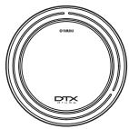
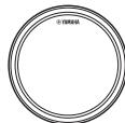
XP80 Snare Pad (x1)
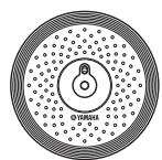
PCY135 Cymbal Pad (x1)

PCY100 Cymbal Pad (x2)
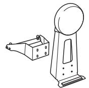
KP65 Kick Pad (x1)
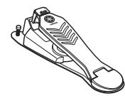
HH65 Hi-hat Controller (x1)
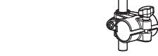
Hi-hat holder (x1)
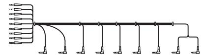
Nine-channel snake cable (x1)

Stopper for PCY100 and PCY135 (x3)
Cable band (x6)

Tuning key (x1)
RS502 Electronic Drum Rack (x1) RS502 Owner's Manual (x1)
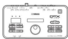
DTX502 Drum Module (x1)
Power adaptor (x1)
May not be included depending on your particular area. Please check with your Yamaha dealer.

Module holder (x1)
Module holder screw (x2)
DTX502 Owner's Manual (x1)

Felt pad for PCY135 (x1)

Felt pad for PCY100 (x2)
- DTX522K/DTX542K Assembly Manual (this booklet; x1)
PCY100/135/155 Owner's Manual (x1)
□ HH65 Owner's Manual (
XP70/80 Owner's Manual (x1)
KP65 Owner's Manual (x1)

Components of DTX542K only
XP70 Tom Pad (x3)
Clamp bolt (for XP70 or XP80; x4)

Components of DTX522K only
TP70 Tom Pad (x3)

Clamp bolt (for XP80; x1)

Wing bolt (for TP70; x3)
TP70 Owner's Manual (x1)


Assemble the RS502 Electronic Drum Rack.
For instructions on how to assemble the RS502 Electronic Drum Rack, refer to the Owner's Manual that came with it.

Assemble the hi-hat holder, the pads, and the drum module to the electronic drum rack.
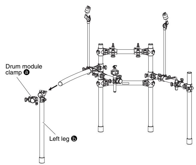
Assembling the hi-hat holder
1. Remove the drum module clamp ③ and the left leg ⑤ from the left side of the rack.
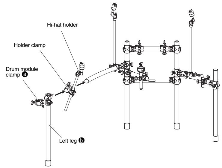
2. Assemble the holder clamp for the hi-hat holder, ensuring that it is oriented as shown in the figure. Following this, reassemble the left leg b and the drum module clamp a .
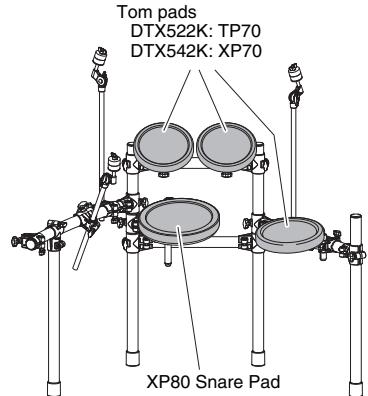
Assembling the snare and tom pads
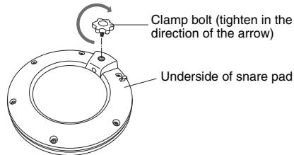
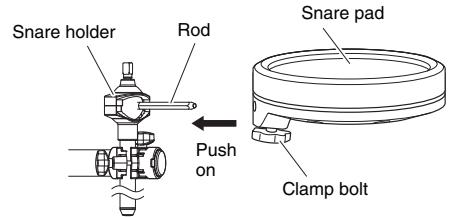
Snare pad
- Attach a clamp bolt to the snare pad and provisionally tighten (by five or six turns).
- Push the snare pad onto the rack's snare holder. Ensure that the snare holder's rod is fully inserted into the snare pad's mounting hole, and then tighten the clamp bolt to secure the pad in place.
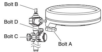
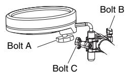
- Loosen bolts A to D as shown below to adjust the height and angle of the snare pad's playing surface. When correctly positioned, be sure to securely tighten the bolts before proceeding to the next step.
Tompads
-
As with the snare pad, attach a wing bolt (DTX522K) or clamp bolt (DTX542K) to each of the three tom pads and provisionally tighten (by five or six turns).
-
Push each of the tom pads onto one of the rack's tom holders. Each time, ensure that the tom holder's rod is fully inserted into the tom pad's mounting hole, and then tighten the bolt to secure the pad in place.
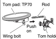
DTX522K
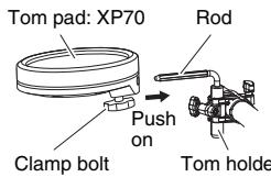
DTX542K
- Loosen bolts A to C as shown below to adjust the height and angle of each tom pad's playing surface. When correctly positioned, be sure to securely tighten the bolts before proceeding to the next step.
* DTX542K shown.
Assembling the drum module, cymbal pads, and hi-hat pad
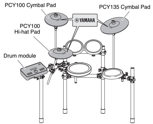
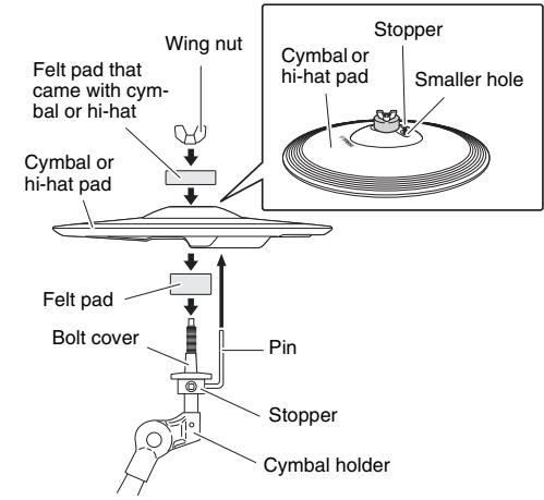
A cymbal pad's built-in sensor is located close to the Yamaha logo found on the top surface. In order to achieve the best performance from your pad, position it such that the area around the logo can be easily struck. (See the figure above.)
- Secure the module holder to the bottom of the drum module using the module holder screws.
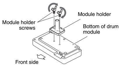
■ Drum module
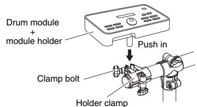
- Push the module holder into the holder clamp and tighten the clamp bolt to secure it in place.
Each cymbal and hi-hat pad
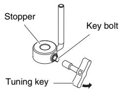
- Using the tuning key, loosen the stopper's key bolt.
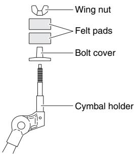
- Remove the wing nut, the two felt pads, and the bolt cover from the cymbal holder.
-
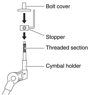
Place the stopper on the cymbal holder.
-
If the key bolt was not sufficiently loosened in Step 1 above, it may not be possible to pass the stopper over the cymbal holder's shaft. In such a case, loosen the key bolt as much as possible without removing it.
-
Replace the bolt cover.
-
Turn the bolt cover to tighten it onto the threaded section and firmly secure it in place.
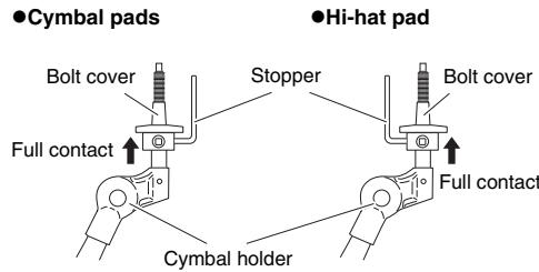
- With the stopper making full contact with the bottom surface of the bolt cover as shown below, tighten the stopper's key bolt using the tuning key.
-
Place one of the felt pads removed in Step 2 on the cymbal holder.
-
Mount the pad on the cymbal stand. Lower the pad into place with the cymbal holder's shaft passing through the central hole. When mounted, the stopper's pin should rest inside the pad's smaller hole.
-
If you were to play your cymbal or hi-hat pad without the stopper's pin positioned well inside the smaller hole, the pad could rotate, causing the cable to be pulled out. It is very important, therefore, to ensure that the stopper is secured as shown in Step 5 above.
-
Assemble the felt pad that came with the hi-hat or cymbal pad.
The second felt pad removed from the cymbal holder in Step 2 above is not required for assembly.
- Tighten the wing nut to secure the pad to the cymbal holder.
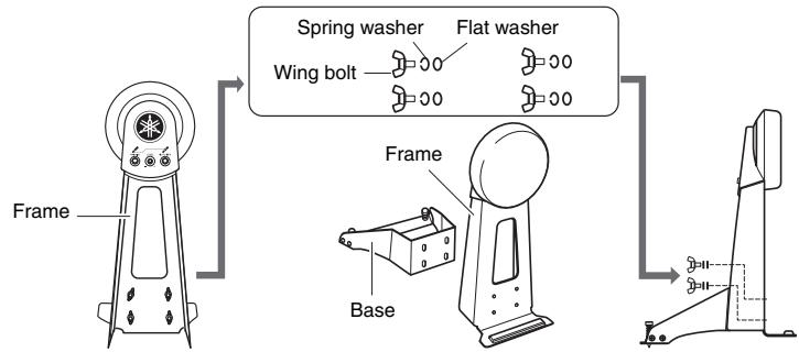
Assembling the kick pad
- If a drum mat (sold separately) is not available, lay a sheet of cardboard on the floor to prevent it from being scratched.
- Remove the four wing bolts, spring washers, and flat washers from the kick pad frame, and line up each set nearby in the order of removal.
- Join the base section to the frame as shown on the right, and then secure it in place by assembling the wing bolts, spring washers, and flat washers removed in the previous step from the base side.
Arrange the hi-hat controller and the kick pad as shown in Example of standard assembly on the other side of this sheet. NOTICE Lay a drum mat (sold separately) on the floor underneath the hi-hat controller and the kick pad. Alternatively, you can place cardboard from the drum kit packaging or the like on the floor to prevent it from being scratched.
5 Connect the pads to the drum module. Connect the output of each pad to the corresponding drum-module input.
-
Plug the straight ends of the nine-channel snake cable into the trigger input jacks ([SNARE] to [HI-HAT] and [HI-HAT CONTROL]) on the back of the drum module.
-
When using the standard setup, the stickers on each of the snake cable's plugs will indicate the name of the corresponding pad.
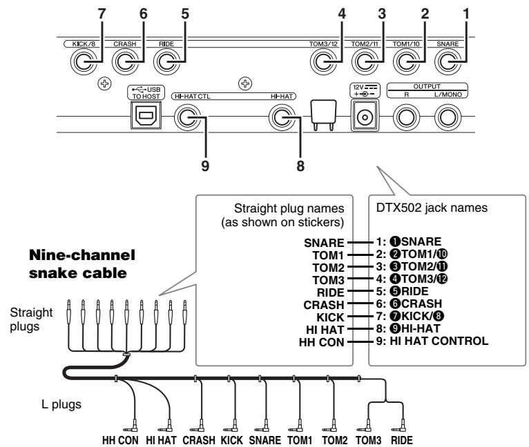
Drum-module rear panel
- Plug the L-shaped ends of the nine-channel snake cable into the corresponding pads.
Locations of pad jacks
- In the case of snare and tom pads, wrap the cables around the cable clips to prevent them from being pulled out.

Excessive bending can damage pad cables. Ensure, therefore, that these cables are not bent at an extreme angle when wrapped around the clips.
6 Connect the power adaptor to the drum module.
- Ensure that the drum module is turned off, and then plug the power adaptor's DC cord into the 12V connector. Hook the power adaptor's DC cord around the cord clip to secure it in place.
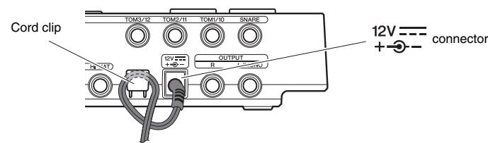
Drum-module rear panel
- Using the cable bands, secure the cables to the kit rack at the positions circled in the figure on the right. (O)
- Plug the adaptor's AC cord into a domestic wall socket.
- IMPORTANT
- NOTICE
- Safety Precautions
- Please read carefully before proceeding.
- Failure to observe the precautions described below can result in serious injury or even death.
- CAUTION Failure to observe the precautions described below can result in injury and/or property damage.
- NOTICE: Usage Precautions
- Assemble the RS502 Electronic Drum Rack.
- Assemble the hi-hat holder, the pads, and the drum module to the electronic drum rack.
- Assembling the snare and tom pads
- Tompads
- Assembling the drum module, cymbal pads, and hi-hat pad
- Each cymbal and hi-hat pad
- Assembling the kick pad
- Connect the power adaptor to the drum module.
Marque : YAMAHA
Modèle : DTX522K/DTX542K
Catégorie : Batterie électronique