
DTXPLORER BASIC SET - Batterie électronique YAMAHA - Notice d'utilisation et mode d'emploi gratuit
Retrouvez gratuitement la notice de l'appareil DTXPLORER BASIC SET YAMAHA au format PDF.
| Type de produit | Batterie électronique |
| Marque | YAMAHA |
| Modèle | DTXPLORER BASIC SET |
| Catégorie | Batterie électronique |
| Alimentation | Adaptateur secteur 12V CC |
| Module de déclenchement | DTXPL (Drum Trigger Module) |
| Pads inclus | 5 x TP65 (Pad de batterie), 1 x KP65 (Pad de grosse caisse) |
| Pads cymbale | 2 x PCY65 (Pad cymbale mono-zone) |
| Contrôleur hi-hat | HH65 |
| Pédale | FP6110A (Pédale de grosse caisse) |
| Support | Rack RS40 |
| Câble de connexion | Câble snake 9 canaux |
| Dimensions du rack | Environ 130 cm de largeur (estimé) |
| Poids total | Environ 12 kg (estimé avec tous les composants) |
| Entretien et nettoyage | Chiffon doux ou légèrement humide, éviter solvants, benzine, alcool |
| Sécurité | Ne pas laisser les enfants assembler seuls ; utiliser sur surface plane et stable ; serrer tous les boulons ; ne pas altérer le produit |
FOIRE AUX QUESTIONS - DTXPLORER BASIC SET YAMAHA
Questions des utilisateurs sur DTXPLORER BASIC SET YAMAHA
0 question sur cet appareil. Repondez a celles que vous connaissez ou posez la votre.
Poser une nouvelle question sur cet appareil
Téléchargez la notice de votre Batterie électronique au format PDF gratuitement ! Retrouvez votre notice DTXPLORER BASIC SET - YAMAHA et reprennez votre appareil électronique en main. Sur cette page sont publiés tous les documents nécessaires à l'utilisation de votre appareil DTXPLORER BASIC SET de la marque YAMAHA.
MODE D'EMPLOI DTXPLORER BASIC SET YAMAHA
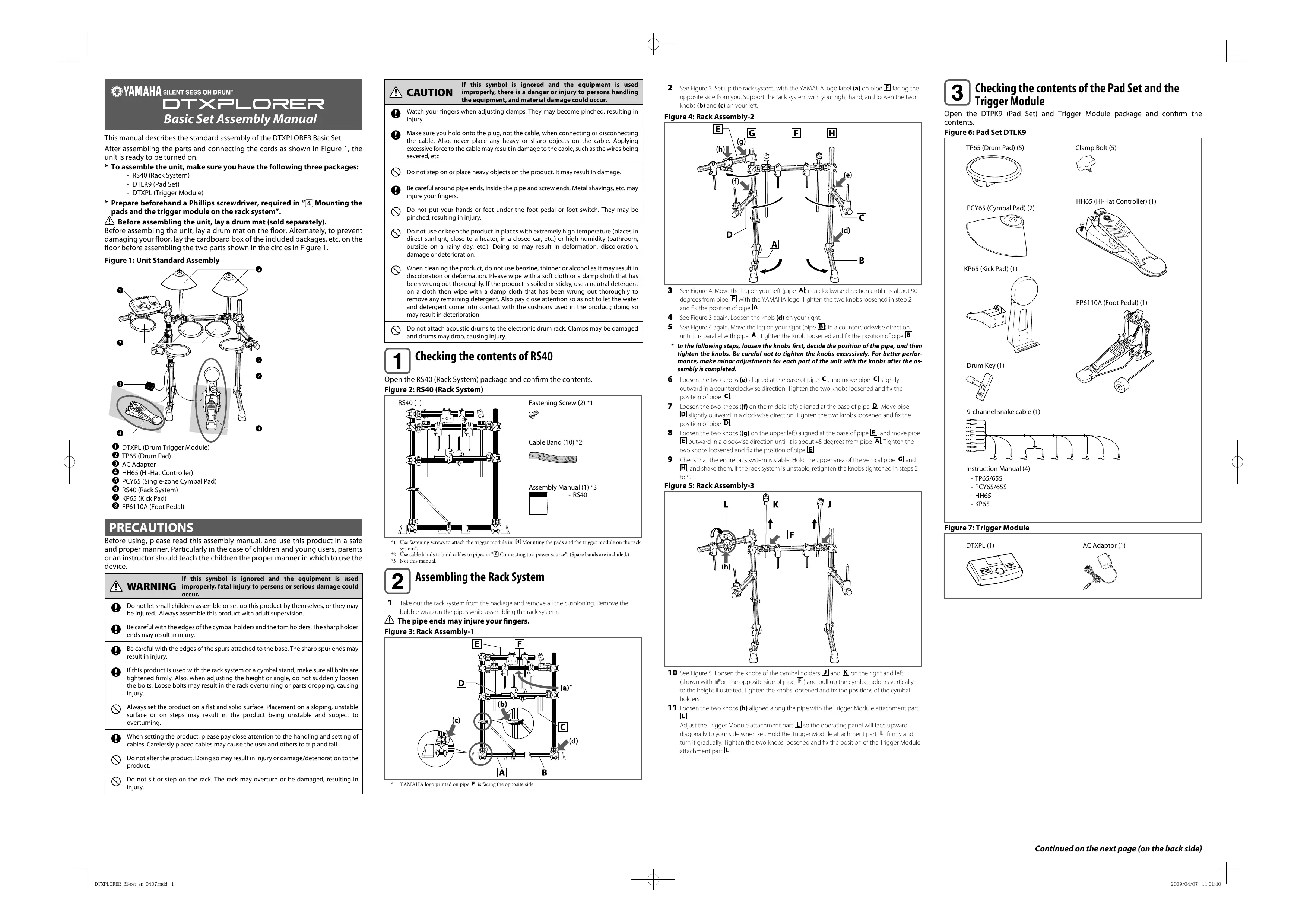
This manual describes the standard assembly of the DTXPLORER Basic Set.
After assembling the parts and connecting the cords as shown in Figure 1, the unit is ready to be turned on.
-
To assemble the unit, make sure you have the following three packages:
-
RS40 (Rack System)
- DTLK9 (Pad Set)
-
DTXPL (Trigger Module)
-
Prepare beforehand a Phillips screwdriver, required in "④ Mounting the pads and the trigger module on the rack system".
Before assembling the unit, lay a drum mat (sold separately).
Before assembling the unit, lay a drum mat on the floor. Alternately, to prevent damaging your floor, lay the cardboard box of the included packages, etc. on the floor before assembling the two parts shown in the circles in Figure 1.
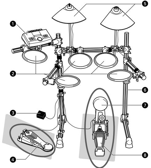
Figure 1: Unit Standard Assembly
DTXPL (Drum Trigger Module)
2 TP65 (Drum Pad)
3 AC Adaptor
HH65 (Hi-Hat Controller)
PCY65 (Single-zone Cymbal Pad)
RS40 (Rack System)
KP65 (Kick Pad)
FP6110A (Foot Pedal)
PRECAUTIONS
Before using, please read this assembly manual, and use this product in a safe and proper manner. Particularly in the case of children and young users, parents or an instructor should teach the children the proper manner in which to use the device.
WARNING
If this symbol is ignored and the equipment is used improperly, fatal injury to persons or serious damage could occur.

Do not let small children assemble or set up this product by themselves, or they may be injured. Always assemble this product with adult supervision.

Be careful with the edges of the cymbal holders and the tom holders. The sharp holder ends may result in injury.

Be careful with the edges of the spurs attached to the base. The sharp spur ends may result in injury.

If this product is used with the rack system or a cymbal stand, make sure all bolts are tightened firmly. Also, when adjusting the height or angle, do not suddenly loosen the bolts. Loose bolts may result in the rack overturning or parts dropping, causing injury.

Always set the product on a flat and solid surface. Placement on a sloping, unstable surface or on steps may result in the product being unstable and subject to overturning.

When setting the product, please pay close attention to the handling and setting of cables. Carelessly placed cables may cause the user and others to trip and fall.

Do not alter the product. Doing so may result in injury or damage/deterioration to the product.

Do not sit or step on the rack. The rack may overturn or be damaged, resulting in injury.

CAUTION
If this symbol is ignored and the equipment is used improperly, there is a danger or injury to persons handling the equipment, and material damage could occur.

Watch your fingers when adjusting clamps. They may become pinched, resulting in injury.

Make sure you hold onto the plug, not the cable, when connecting or disconnecting the cable. Also, never place any heavy or sharp objects on the cable. Applying excessive force to the cable may result in damage to the cable, such as the wires being severed, etc.

Do not step on or place heavy objects on the product. It may result in damage.

Be careful around pipe ends, inside the pipe and screw ends. Metal shavings, etc. may injure your fingers.

Do not put your hands or feet under the foot pedal or foot switch. They may be pinched, resulting in injury.

Do not use or keep the product in places with extremely high temperature (places in direct sunlight, close to a heater, in a closed car, etc.) or high humidity (bathroom, outside on a rainy day, etc.). Doing so may result in deformation, discoloration, damage or deterioration.

When cleaning the product, do not use benzine, thinner or alcohol as it may result in discoloration or deformation. Please wipe with a soft cloth or a damp cloth that has been wrung out thoroughly. If the product is soiled or sticky, use a neutral detergent on a cloth then wipe with a damp cloth that has been wrung out thoroughly to remove any remaining detergent. Also pay close attention so as not to let the water and detergent come into contact with the cushions used in the product; doing so may result in deterioration.

- Do not attach acoustic drums to the electronic drum rack. Clamps may be damaged and drums may drop, causing injury.

Checking the contents of RS40
Open the RS40 (Rack System) package and confirm the contents.
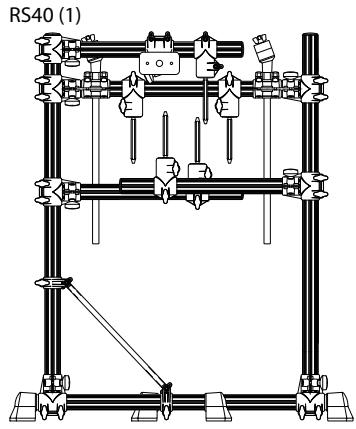
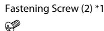
Figure 2: RS40 (Rack System)
Cable Band (10) *2
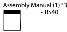
*1 Use fastening screws to attach the trigger module in “④ Mounting the pads and the trigger module on the rack system”
*2 Use cable bands to bind cables to pipes in Connecting to a power source". (Spare bands are included.)
*3 Not this manual.

Assembling the Rack System
1 Take out the rack system from the package and remove all the cushioning. Remove the bubble wrap on the pipes while assembling the rack system.
The pipe ends may injure your fingers.
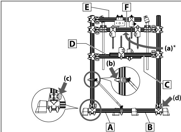
Figure 3: Rack Assembly-1
YAMAHA logo printed on pipe is facing the opposite side.
2 See Figure 3. Set up the rack system, with the YAMAHA logo label (a) on pipe F facing the opposite side from you. Support the rack system with your right hand, and loosen the two knobs (b) and (c) on your left.
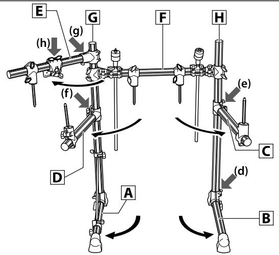
Figure 4: Rack Assembly-2
3 See Figure 4. Move the leg on your left (pipe A) in a clockwise direction until it is about 90 degrees from pipe F with the YAMAHA logo. Tighten the two knobs loosened in step 2 and fix the position of pipe A.
4 See Figure 3 again. Loosen the knob (d) on your right.
5 See Figure 4 again. Move the leg on your right (pipe B) in a counterclockwise direction until it is parallel with pipe A. Tighten the knob loosened and fix the position of pipe B.
- In the following steps, loosen the knobs first, decide the position of the pipe, and then tighten the knobs. Be careful not to tighten the knobs excessively. For better performance, make minor adjustments for each part of the unit with the knobs after the assembly is completed.
6 Loosen the two knobs (e) aligned at the base of pipe , and move pipe slightly outward in a counterclockwise direction. Tighten the two knobs loosened and fix the position of pipe .
7 Loosen the two knobs (f) on the middle left) aligned at the base of pipe D. Move pipe D slightly outward in a clockwise direction. Tighten the two knobs loosened and fix the position of pipe D.
8 Loosen the two knobs (g) on the upper left) aligned at the base of pipe E, and move pipe E outward in a clockwise direction until it is about 45 degrees from pipe A. Tighten the two knobs loosened and fix the position of pipe E.
9 Check that the entire rack system is stable. Hold the upper area of the vertical pipe and , and shake them. If the rack system is unstable, retighten the knobs tightened in steps 2 to 5.
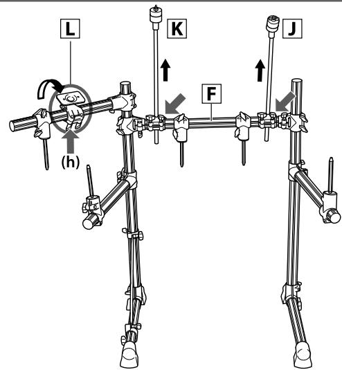
Figure 5: Rack Assembly-3
10 See Figure 5. Loosen the knobs of the cymbal holders J and K on the right and left (shown with on the opposite side of pipe F ) and pull up the cymbal holders vertically to the height illustrated. Tighten the knobs loosened and fix the positions of the cymbal holders.
11 Loosen the two knobs (h) aligned along the pipe with the Trigger Module attachment part L.
Adjust the Trigger Module attachment part so the operating panel will face upward diagonally to your side when set. Hold the Trigger Module attachment part firmly and turn it gradually. Tighten the two knobs loosened and fix the position of the Trigger Module attachment part .

Checking the contents of the Pad Set and the Trigger Module
Open the DTPK9 (Pad Set) and Trigger Module package and confirm the contents.
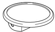
Figure 6: Pad Set DTLK9
TP65 (Drum Pad) (5)
PCY65 (Cymbal Pad) (2)
KP65 (Kick Pad) (1)

Clamp Bolt (5)
HH65 (Hi-Hat Controller) (1)
FP6110A (Foot Pedal) (1)

Drum Key (1)
9-channel snake cable (1)
Instruction Manual (4)
- TP65/65S
-PCY65/65S
HH65 - KP65
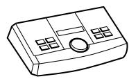
Figure 7: Trigger Module
DTXPL (1)
AC Adaptor (1)
Mounting the pads and the trigger module on the rack system
Mount the pads and the trigger module on the rack system. Then position the kick pad and the hi-hat.
Mounting the TP65 (Drum pads) on the rack system
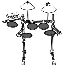
Figure 8: Pads Assembly-1
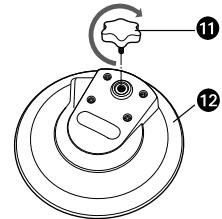
Figure 9:TP65
1 Clamp bolt
TP65 (Rear side)
1 See Figure 9.
Attach the clamp bolts (1) on TP65s (12). Tighten the clamp bolts five to six turns each.
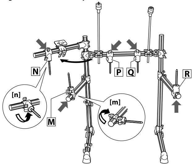
Figure 10: Pads Assembly-2
2 See Figure 10.
Loosen the knob (shown with ) of the tom holder on the middle left. Move the tom holder inward as shown in the close-up illustration (m) . Then tighten the knob and attach the tom holder firmly at a position where it points slightly downward.
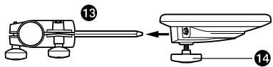
Figure 11: Tom Holder and Drum Pad
Tom holder
14 Clamp bolt
3 Attach the TP65 (Drum pad) to the tom holder as shown in Figure 11. Tighten the clamp bolt and attach the drum pad TP65 firmly.
4 See Figure 10 again. Loosen the knob (shown with ) of the tom holder on the upper left. Move the tom holder inward as shown in the close-up illustration (n). Then tighten the knob and attach the tom holder firmly at a position where it points slightly downward.
5 Attach the TP65 (Drum pad) to the tom holder [N]. Tighten the clamp bolt and attach the drum pad TP65 firmly.
6 Repeat step 4 and 5 in the same manner for tom holders and at the center of the rack system and for tom holder on the right, and attach the TP65 (Drum pad) to each tom holder.
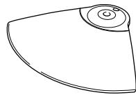
Mounting the PCY65 (Cymbal pads) on the rack system
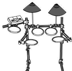
Figure 12: Pads Assembly-3
Figure 13: Cymbal holder-1
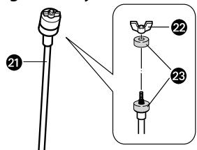
Cymbal holder
2 Wing nut
Felt washer
1 See Figure 13. Remove the wing nut (22) and one of the felt washers (23) from the cymbal holder (24).
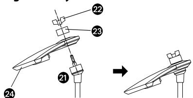
Figure 14: Cymbal holder-2
PCY65 (Cymbal pad)
2 Attach the PCY65 (Cymbal pad) to the cymbal holder (21) as shown in Figure 14. Attach
the felt washer (23) and the wing nut (22) removed in step 1, and tighten it.
Turn the wing nut until you are certain that the cymbal pad is attached. The cymbal pad is
designed to shake when you hit the surface, even when the wing nut is tightened securely
Mounting the DTXPL (Trigger module)
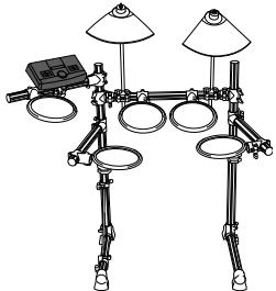
Figure 15: Pads Assembly-4
Figure 16: Module stand-1
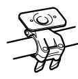
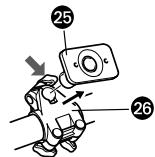
1 See Figure 16. Loosen the knob of the clamp (26) (shown with ) and remove the module stand (25) from the clamp (26).
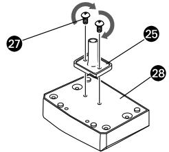
Figure 17: Module stand-2
Fastening screw
28DTXPL (Rear side)
- The fastening screws are included in the same plastic bag that includes the Assembly Manual of rack system RS40. The plastic bag is packaged between the space within the cardboards used for cushioning.
2 Tighten the fastening screws (27) with a Phillips screwdriver, as shown in Figure 17, to attach the module stand (25) onto the rear side of the trigger module (28).
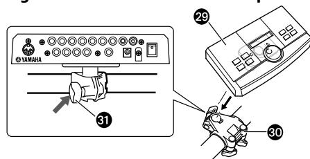
Figure 18: Module stand and clamp
29 DTXPL + Module stand
30 Clamp
Knob
3 Attach the module stand (29) onto the clamp (30). Tighten the knob (31) and fix the position.
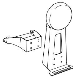
Assembling the KP65 (Kick pad)
1 If a drum mat (sold separately) is not available, lay a cardboard on the floor to prevent scratching the surface.
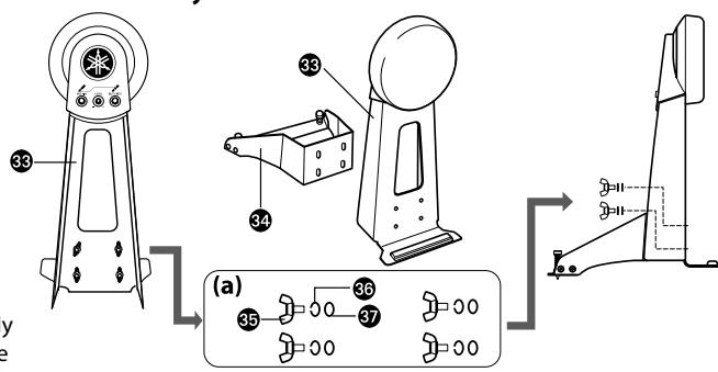
Figure 19: KP65 Assembly
33 Body
34 Base
5 Wing bolt
Spring washer
37 Washer
2 Remove the wing bolt (5), the spring washer (36) and the washer (7) from the body (38) and keep the four sets nearby in the order removed.
* If the wing bolt, the spring washer and/or the washer are separated from each other, set them as illustrated in Figure 19-(a).
3 Set the base (24) on the body (33), and attach them using the wing bolt, the spring washer and the washer removed in step 2.
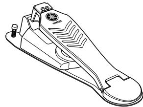
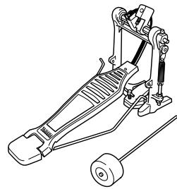
Assembling the FP6110A (Foot pedal)
1 If a drum mat (sold separately) is not available, lay a cardboard on the floor to prevent scratching the surface.
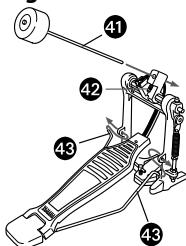
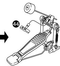
Figure 20: FP6110A Assembly
Beater
Beater locking bolt
Radius rod
4 Drum key
2 Insert the radius rod (48) into the hole of the frame as shown in Figure 20.
3 Insert the beater (4) into the hole of the beater attachment part until the further end of the beater slides outward about 15 mm. Tighten the beater locking bolt (2) using the drum key
(44)
Attaching the FP6110A (Foot pedal) to KP65 (Kick pad)
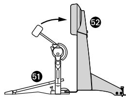
Figure 21: FP6110A and KP65
FP6110A (Foot pedal)
KP65 (Kick pad)
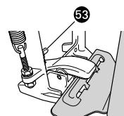
T-handlet bolt
1 Turn the T-handlet bolt (53) of the foot pedal (51) in a counterclockwise direction and loosen it.
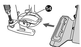
Figure 23: Attaching FP6110A

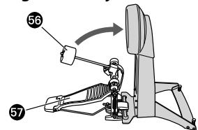
OA Figure 24: Adjustment
54 Hoop clamp
55 Convex part
56 Beater head
57 Pedal
2 Attach the convex part (55) of the kick pad to the hoop clamp (54).
3 Turn the T-handlet bolt (53) in a clockwise direction and tighten it.
4 Step on the pedal and check if the head of the beater hits the center area of the kick pad. Adjust the length of the beater and/or position the pedal to the right or left if necessary.
Installing the HH65(Hi-hat controller) and KP65 (Kick pad)
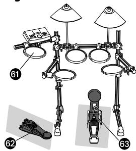
Figure 25: Hi-Hat and KP65
1 If a drum mat (sold separately) is not available, lay a cardboard on the floor to prevent scratching the surface.
2 Place the HH65 (Hi-hat controller) (62) under the TP65 (Hi-hat cymbal) (61).
3 Place the KP65 (Kick pad) with FP6110A (Foot pedal) (33) at the bottom center of the RS40 (rack system).
⑤ TP65 (Hi-hat cymbal)
62 HH65 (Hi-hat controller)
KP65 (Kick pad) + FP6110A (Foot pedal)

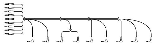
Connecting the pads to the Trigger Module
Connect the output jacks of the pad and the input jacks of the trigger module with the 9-channel snake cable.
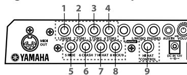
Figure 26:DTXPL (Rear panel)
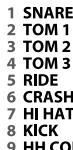
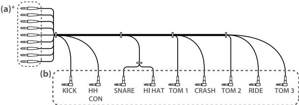
Figure 27: 9-channel Snake Cable
- Each straight plug is labeled indicating the input jacks to which they are to be connected.
1 Insert the straight plugs (Figure 27-(a)) of the 9-channel snake cable into the input jacks on the rear panel of the trigger module. For standard assembly, connect the straight plugs to the input jacks in accordance with the indication on each label.
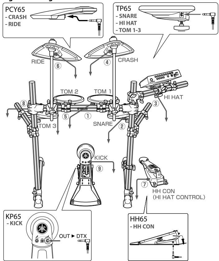
Figure 28: Diagram of standard connection
2 Insert the L-shaped plugs (Figure 27-(b)) of the 9-channel snake cable into each corresponding pad. It is recommended to connect the cables in order from numbers ① to ⑨ shown in Figure 28 (from the shortest cable to the longest cable).

Connecting to a power source
Connect the AC adaptor to the DTXPL.
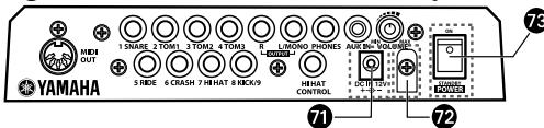
Figure 29: Power switch (DTXPL rear panel)
Power supply jack (DC IN 12V)
12 Cable clip
73 Power switch
1 Make sure to turn the power off (the Standby/
On switch (73) is set to the standby position).
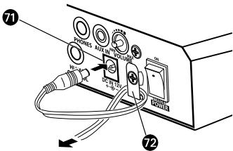
Figure 30: Cable clip (DTXPL rear panel)
2 Attach the AC adaptor to connect to a power source.
Insert the DC plug into the power supply jack.
(7) and twist the cable around the cable clip
(7) to prevent the DC plug from falling out.
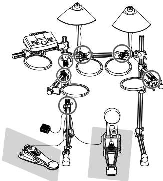
Figure 31: Using Cable Band
3 Use the cable bands to bind the cables to the pipes at the six points shown with the circles.
* Leaving the cable slacked may interfere with your performance.
The assembly is now completed.
- To check the actual sound, connect the unit with an amplified speaker or a headphone before turning on the power.
- PRECAUTIONS
- WARNING
- CAUTION
- Checking the contents of RS40
- Assembling the Rack System
- Checking the contents of the Pad Set and the Trigger Module
- Mounting the pads and the trigger module on the rack system
- Mounting the TP65 (Drum pads) on the rack system
- Mounting the PCY65 (Cymbal pads) on the rack system
- Mounting the DTXPL (Trigger module)
- Assembling the KP65 (Kick pad)
- Assembling the FP6110A (Foot pedal)
- Attaching the FP6110A (Foot pedal) to KP65 (Kick pad)
- Installing the HH65(Hi-hat controller) and KP65 (Kick pad)
- Connecting the pads to the Trigger Module
- Connecting to a power source
Marque : YAMAHA
Modèle : DTXPLORER BASIC SET
Catégorie : Batterie électronique