
DTX950K - Batterie électronique YAMAHA - Notice d'utilisation et mode d'emploi gratuit
Retrouvez gratuitement la notice de l'appareil DTX950K YAMAHA au format PDF.

| Type de produit | Batterie électronique |
| Marque | YAMAHA |
| Modèle | DTX950K |
| Composants inclus | Module de déclenchement DTX900, rack HXR4LD, pads PCY135 (x2), PCY155, RHH135, KP125W, XP120T (x2), XP120SD, supports CH750 (x2), CH755, SS662, HS740A, câbles, clé d'accord |
| Alimentation | Adaptateur secteur CA (100-240 V) inclus |
| Fonctions principales | Déclenchement multi-zones, sons de batterie acoustique et électronique, métronome, enregistrement |
| Nombre de pads | 8 (2 cymbales PCY135, 1 cymbale PCY155, 1 hi-hat RHH135, 1 grosse caisse KP125W, 2 toms XP120T, 1 caisse claire XP120SD) |
| Dimensions du rack | Env. 150 x 100 x 80 cm (assemblé) |
| Poids total | Env. 25 kg (avec tous les composants) |
| Matériau des pads | Caoutchouc, plastique ABS |
| Entretien et nettoyage | Chiffon doux sec ou légèrement humide. Ne pas utiliser de benzène, diluant ou alcool. |
| Sécurité | Utiliser sur surface plane. Ne pas s'asseoir ou marcher sur le rack. Surveiller les enfants. Serrer tous les boulons. |
| Pièces détachées et réparabilité | Pièces de rechange disponibles auprès des revendeurs Yamaha agréés |
| Garantie | Consulter la documentation fournie |
| Accessoires optionnels | Tapis de batterie, pédale de grosse caisse (vendus séparément) |
FOIRE AUX QUESTIONS - DTX950K YAMAHA
Questions des utilisateurs sur DTX950K YAMAHA
0 question sur cet appareil. Repondez a celles que vous connaissez ou posez la votre.
Poser une nouvelle question sur cet appareil
Téléchargez la notice de votre Batterie électronique au format PDF gratuitement ! Retrouvez votre notice DTX950K - YAMAHA et reprennez votre appareil électronique en main. Sur cette page sont publiés tous les documents nécessaires à l'utilisation de votre appareil DTX950K de la marque YAMAHA.
MODE D'EMPLOI DTX950K YAMAHA
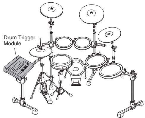
This manual describes the standard assembly of the DTX950K.
After assembling the parts and connecting the cords as shown below, the Drum Trigger Module is ready to be turned on.
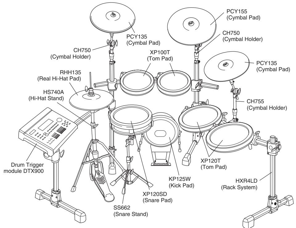
Unit Standard Assembly
IMPORTANT
- To assemble the unit, make sure you have the following four packages: HXR4LD (Rack System), DTP900 (Pad Set), DTP902 (Pad Set), DTX900 (Drum Trigger Module).
- This manual covers how to attach the Pads and Drum Trigger Module to the Rack System HXR4LD, for which assembly has already been completed. Before performing the instructions described in this manual, make sure to complete the Rack System HXR4LD by following the corresponding Assembly Manual.
NOTICE
Before assembling the unit, lay a drum mat (sold separately) on the floor. Alternately, to prevent damaging the floor, lay the cardboard of the included packages, etc. on the floor before handling the Hi-Hat Stand HS740A and Kick Pad KP125W.
PRECAUTIONS
Before using, please read this assembly manual, and use this product in a safe and proper manner.
- Please keep this manual in a safe place for future reference.
- Make sure to read the Assembly Manual of the Rack System and the Owner's Manual of the Pad.

WARNING
If this symbol is ignored and the equipment is used improperly, fatal injury to persons or serious damage could occur.
- Do not let small children assemble or set up this product by themselves, or they may be injured. Always assemble this product with adult supervision.
- Be careful with the edges of the Cymbal Holders and the Tom Holders. The sharp holder ends may result in injury.
- Be careful with the edges of the spurs attached to the Kick Pad and foot pedal. The sharp ends may result in injury.
- If this product is used with a Rack System or Cymbal Stand, make sure all bolts are tightened firmly. Also, when adjusting the height or angle, do not suddenly loosen the bolts. Loose bolts may result in the rack overturning or parts dropping, causing injury.
- Always set the product on a flat and solid surface. Placement on a sloping, unstable surface or on steps may result in the product being unstable and subject to overturning.
- When setting up the product, please pay close attention to the handling and setting of cables. Carelessly placed cables may cause the user and others to trip and fall.
- Do not alter the product. Doing so may result in injury or damage/deterioration to the product.
- Do not sit or step on the rack. The rack may overturn or be damaged, resulting in injury.

CAUTION
If this symbol is ignored and the equipment is used improperly, there is a danger or injury to persons handling the equipment, and material damage could occur.
- Watch your fingers when adjusting clamps. They may become pinched, resulting in injury.
- Be careful around pipe ends, inside the pipe and screw ends. Metal shavings, etc. may injure your fingers.
- Do not put your hands or feet under the foot pedal or foot switch. They may be pinched, resulting in injury.
- Do not attach acoustic drums to the electronic drum rack. Clamps may be damaged and drums may drop, causing injury.
NOTICE
- Make sure you hold onto the plug, not the cable, when connecting or disconnecting the cable. Also, never place any heavy or sharp objects on the cable. Applying excessive force to the cable may result in damage to the cable, such as the wires being severed, etc.
- Do not step on or place heavy objects on the product. It may result in damage.
- Do not use or keep the product in places with extremely high temperature (places in direct sunlight, close to a heater, in a closed car, etc.) or high humidity (bathroom, outside on a rainy day, etc.). Doing so may result in deformation, discoloration, damage or deterioration.
-
When cleaning the product, do not use benzine, thinner or alcohol as it may result in discoloration or deformation. Please wipe with a soft cloth or a damp cloth that has been wrung out thoroughly. If the product is soiled or sticky, use a neutral detergent on a cloth then wipe with a damp cloth that has been wrung out thoroughly to remove any remaining detergent. Also pay close attention so as not to let the water and detergent come into contact with the cushions used in the product; doing so may result in deterioration.
-
Specifications and descriptions in this owner's manual are for information purposes only. Yamaha Corp. reserves the right to change or modify products or specifications at any time without prior notice. Since specifications, equipment or options may not be the same in every locale, please check with your Yamaha dealer.

Checking the contents of each package
Package 1 [DTP900]
PCY135
(Cymbal Pad) (2)
PCY155
Cymbal Pad) (1)
□ RHH135
Real Hi-Hat Pad)1
![YAMAHA DTX950K - Package 1 [DTP900] - 1](/content/2025/01/114993/images/b5d17d43a89bee2ff51004931463bc240cf470eb7d91e75042b7a6bb7f6027f7.jpg)
![YAMAHA DTX950K - Package 1 [DTP900] - 2](/content/2025/01/114993/images/ed82a14a3d6d10aa1ab3e79425e096049522b76dd59c1b0850a134e5171f6186.jpg)
![YAMAHA DTX950K - Package 1 [DTP900] - 3](/content/2025/01/114993/images/ca55e42a4767044b5ddd216f412375cdafd7ea1b1ea450ece1b27f4900d542d3.jpg)
Stand base for the RHH135 (1)
![YAMAHA DTX950K - Package 1 [DTP900] - 4](/content/2025/01/114993/images/06f359e41c212079677f681387499595ddfa1b3b9abda23aa66b3e7822b949b2.jpg)
KP125W
(Kick Pad) (1)
CH750
(Cymbal Holder) (2)
SS662
(Snare Stand) (1)
![YAMAHA DTX950K - Package 1 [DTP900] - 5](/content/2025/01/114993/images/28347186763252482cd79402e8651909c3915414ee061972f1c2563377dabe66.jpg)
![YAMAHA DTX950K - Package 1 [DTP900] - 6](/content/2025/01/114993/images/6d3a5e06d33fce341da6591106380ed4c466d35c2211fd0d7f6c3d398d2599cc.jpg)
![YAMAHA DTX950K - Package 1 [DTP900] - 7](/content/2025/01/114993/images/3e610ce5089aa0f7ff1bc20a3328e42252f2128837643cd58e092e4deba1a59f.jpg)
![YAMAHA DTX950K - Package 1 [DTP900] - 8](/content/2025/01/114993/images/204eaec2a7f9b11f072a6e2780f4d8d783b8c8f7d2969d07187d1f944cdb8547.jpg)
2.5m stereo phone cables (7)
4m stereo phone cables (4)
Cable bands (10)
![YAMAHA DTX950K - Package 1 [DTP900] - 9](/content/2025/01/114993/images/78083335f7dfb6be569ea353e313f28b0e8c38b9e4921a2640abd82491605e59.jpg)
![YAMAHA DTX950K - Package 1 [DTP900] - 10](/content/2025/01/114993/images/7b437c78ea0e84e5e400265319c15dfcdf5d0eacecb68c080212eed0432db944.jpg)
![YAMAHA DTX950K - Package 1 [DTP900] - 11](/content/2025/01/114993/images/58a2318e2282a9184c3663e1d6c92fb5359231a12ae1cc7e68db43e4b4c60c92.jpg)
![YAMAHA DTX950K - Package 1 [DTP900] - 12](/content/2025/01/114993/images/b95159f3e73475373e35177fbec4d48bcbc630bead211c6246d0c34a753ff3d6.jpg)
Felts for the PCY135/155 (3)
![YAMAHA DTX950K - Package 1 [DTP900] - 13](/content/2025/01/114993/images/3caa4493b4d1d60d707c2148ec92bc75efeda1346892cfc7fe44e7203815dd74.jpg)
2m spiral tube (1)
You can cut this tube to any desired length and use it in order to take up any slack of the cables.
![YAMAHA DTX950K - Package 1 [DTP900] - 14](/content/2025/01/114993/images/b905a4d9a02c60d02a5956359111b3f26394b22a9a24f8dcfefbadcb8fe8947d.jpg)
Tuning key (1)
![YAMAHA DTX950K - Package 1 [DTP900] - 15](/content/2025/01/114993/images/ffdfeb18df8efc60d18b85fe53906e9e1c910b4a7b8bcb4c826955510fde19b4.jpg)
Owner's Manual
PCY65/65S
KP125W
RHH135
Package 2 [DTP902]
| x - 1| = | x + 2|
00T (Tom Pad) (2)
Clamp bolt (4)
□HS7
(Hi-Hat Stand) (1)
![YAMAHA DTX950K - Package 2 [DTP902] - 1](/content/2025/01/114993/images/3a89c29a6392ce731b1ce70b6c1b683dd457a87778e17fffb594fa2146b4a435.jpg)
![YAMAHA DTX950K - Package 2 [DTP902] - 2](/content/2025/01/114993/images/ec6549bb93d787899086570f7404fb949fa3d2b98378b1beb7d2f815c39f1e4c.jpg)
XP120T (Tom Pad) (2)
Cvmbal Holder) (1)
![YAMAHA DTX950K - Package 2 [DTP902] - 3](/content/2025/01/114993/images/7ee35245507b136db25bb22524631e97ca8f47c4b1dc7a2f082517ce53f1ec7f.jpg)
![YAMAHA DTX950K - Package 2 [DTP902] - 4](/content/2025/01/114993/images/c6c12ff210a7e5275284ad7a9e60371857a62fbff517e810d50c860acd7c7dbb.jpg)
![YAMAHA DTX950K - Package 2 [DTP902] - 5](/content/2025/01/114993/images/1635aa796a146dc4a48f647d211dc1841b4765412b414e02631ac59c98335b00.jpg)
XP120SD (Snare Pad) (1)
![YAMAHA DTX950K - Package 2 [DTP902] - 6](/content/2025/01/114993/images/4b704d5a0867268b72b8748ba48171ea897ee05341dd17187c400e52ae6e8f70.jpg)
XP100T/100SD/120T/120SD Owner's Manual (1)
Assembly Manual (this sheet, 1)
![YAMAHA DTX950K - Package 2 [DTP902] - 7](/content/2025/01/114993/images/b841976fb661ef9c3da47e677ec416c69d5a46795deace7861c9ea637937a3cd.jpg)
Package 3 [Drum Trigger Module DTX900]
Drum Trigger Module DTX900 (1)
Module Stand (1)
AC Power
![YAMAHA DTX950K - Package 3 [Drum Trigger Module DTX900] - 1](/content/2025/01/114993/images/4d5372a760cbd88a26720ad7976dc866f3a64eed6a3bdb16daa2271afa364bed.jpg)
![YAMAHA DTX950K - Package 3 [Drum Trigger Module DTX900] - 2](/content/2025/01/114993/images/83dde574f569d7980d129d600ab5923061b384612827cc5ce4f0a2deb00b4ff0.jpg)
![YAMAHA DTX950K - Package 3 [Drum Trigger Module DTX900] - 3](/content/2025/01/114993/images/d2e2b4139ae9770b72a3dd4e1df1b7eb7114d4dad7baba04e6a78f1f9816fee3.jpg)
Module stand fastening screws (4)
DTX900 Owner's Manual (1)
DTX900 Data List (1)
![YAMAHA DTX950K - Package 3 [Drum Trigger Module DTX900] - 4](/content/2025/01/114993/images/bb84d937376018ebf7a3fee9e6d82713b96733646ac524352126cb9b7ea848b7.jpg)
![YAMAHA DTX950K - Package 3 [Drum Trigger Module DTX900] - 5](/content/2025/01/114993/images/254a3690a69a026d7245da9fdaf96e7018e273165c704e75fa189524070cff98.jpg)
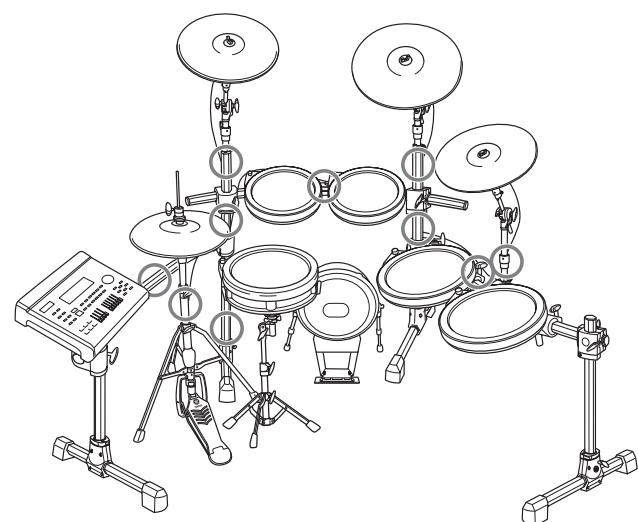
Mounting the Pads and the Drum Trigger Module on the Rack System
Mount the Pads and the Trigger Module on the Rack System. Then position the Kick Pad and the Hi-Hat.
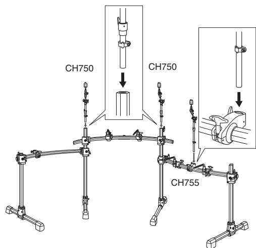
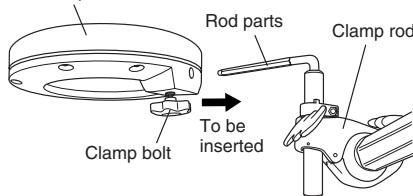
Attaching the Cymbal Holder
- Remove the cap of the rack by loosening the screw on the top of the vertical support.
- Attach the Cymbal Holders (CH750 x 2 and CH755 x 1) to the Rack System as shown below.
Attaching the Tom Pad
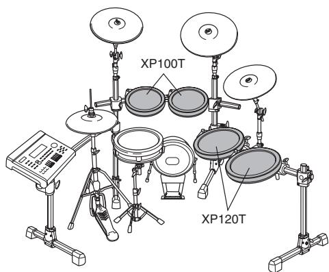
- Attach the clamp bolt then tighten it with five or six turns on each of three Tom Pads.
- Attach four Tom Pads to the clamp rods on the rack respectively. As shown below, attach the Tom Pad to the rod part so that the rod part is to be inserted to the hole of the Tom Pad, then tighten the clamp bolt firmly.
Tom pad
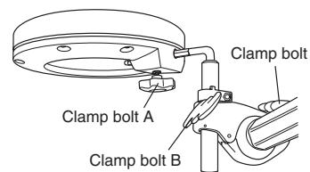
- If you want to change the location (height and angle) of the Tom Pad, use the clamp bolts A, B and C. Loosen the one of the clamp bolts, adjust the location of the Pad, then make sure to tighten the clamp bolts again before adjusting another clamp bolt.
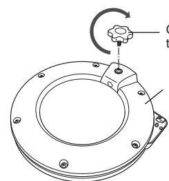
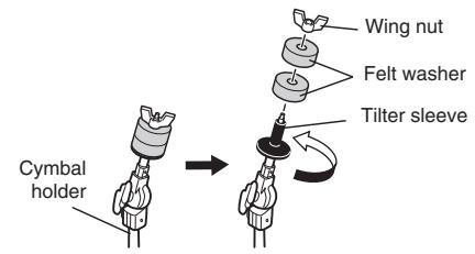
Attaching the Cymbal Pad
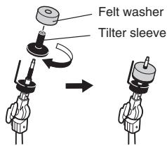
- Remove the wing nut and the two felt washers from the Cymbal Holder. Then turn the tilter sleeve in a counterclockwise direction and remove it.
- Attach the stopper to the Cymbal Holder, and fix at a position where the L-shaped part of the stopper is on the opposite side from you. To fix the position of the stopper, use the tuning key and tighten the key bolt firmly.
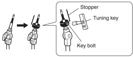
-
Attach the tilter sleeve removed in step 1 to the Cymbal Holder again, and tighten it in a clockwise direction.
-
Attach one of the felt washers removed in step 1 to the Cymbal Holder. The other felt washer will not be used within the standard assembly described in this manual.
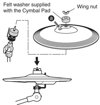
-
Insert the end of the L-shaped part of the stopper into the oval-shaped hole (shown as 3) on the Cymbal Pad to set the Pad on the Holder.
-
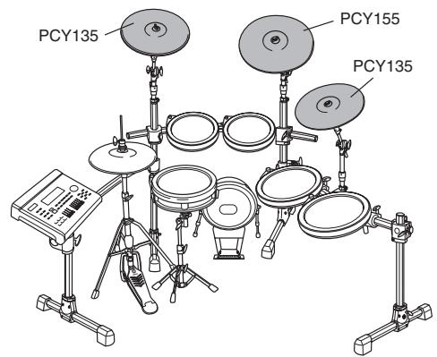
Cymbal Pad PCY135 is very similar to Real High-Hat Pad RHH135. Check the model name on the reverse side.
-
Attach the included round-shaped felt with a large hole-diameter to the Cymbal Holder, then attach the wing nut removed in step 1 and tighten it. Turn the wing nut until you are certain that the Cymbal Pad is attached. The Cymbal Pad is designed to shake when you hit the surface, even when the wing nut is tightened securely.
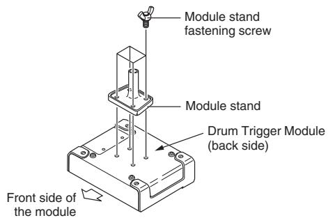
Attaching the Drum Trigger Module
- Attach the included module stand to the back side of the Drum Trigger Module by using the module stand fastening screws.
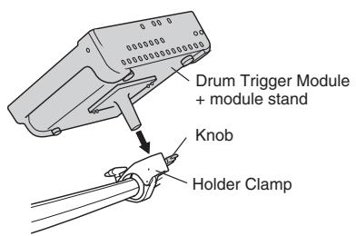
- Attach the module stand onto the holder clamp, then tighten the knob to fix the position.
Assembling the Hi-Hat Stand
- If a drum mat (sold separately) is not available, lay a sheet of cardboard on the floor to prevent scratching the surface.
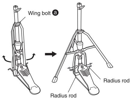
- Loosen the wing bolt (shown with 3) of the Hi-Hat Stand.
- Spread out the legs of the tripod part until it stands stable. Tighten the wing bolt loosened in step 2.
- Insert the radius rod into the hole of the frame as shown below.
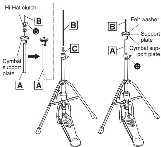
- As shown at right, loosen the wing bolt (shown with b) to remove the hi-hat clutch.
- The hi-hat clutch is not used within the standard assembly described in this manual. Use the hi-hat clutch included in the RHH135.
6.Pull out the hi-hat shaft B from the upper pipe A. - Insert the hi-hat shaft B removed in step 6 into the nut of the lower pipe C.
- Insert the upper pipe A into the hi-hat shaft B from above, then tighten the wing bolt (shown with C at right) at the position where the cymbal support plate is positioned at the middle area of the hi-hat shaft B.
- Remove the felt washer and the cymbal support plate attached above the support plate, since they are not used within the standard assembly described in this manual.
-
Set the Real Hi-Hat Pad RHH135.
-
Refer to "Setting Up" in the RHH135 Owner's Manual.
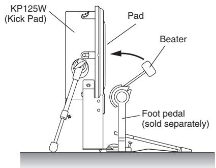
Assembling the Kick Pad
- If a drum mat (sold separately) is not available, lay a sheet of cardboard on the floor to prevent scratching the surface.
-
Attach the foot pedal (sold separately) to the Kick Pad KP125W, then fix the position so that the beater will hit the center of the Pad.
-
Refer to the Owner's Manual of the KP125W.
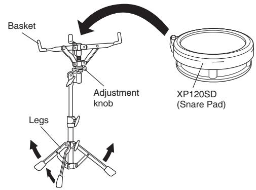
Assembling the Snare Stand and Snare Pad
- Spread out the legs of the tripod part then locate the Snare Stand on the floor.
- Spread out the basket part of the Snare Stand, set the Snare Pad XP120SD on the basket part, then use the adjustment knob to fix the Snare Pad.
4 Locate the Hi-Hat Stand, Kick Pad and Snare Stand as desired, referring to "Unit Standard Assembly" on the front page. 10uBEt the unit, lay a drum mat (sold separately) on the floor. If a drum mat is not available, lay the cardboard of the included package under the Hi-Hat Stand and Kick Pad to prevent damaging the floor.
E Connecting the pads to the Drum Trigger Module
Connect the cables plugged into the Output jacks of the Pads to the Input jacks of the Drum Trigger module.
- As shown at right, connect the Pads with the Trigger Input jacks (SNARE - KICK/ and HI-HAT CONTROL jack) of the Drum Trigg Module by using the stereo phone cables.
- Insert the straight plugs of the cable into the Trigger Input jacks of the Drum Trigger Module, then insert the L-shaped plugs of the cables into each corresponding Pad.
Rear panel of the Drum Trigger Module
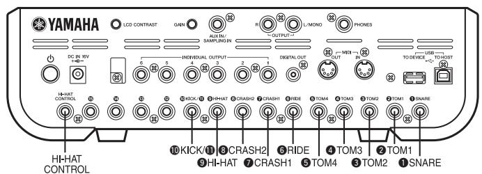
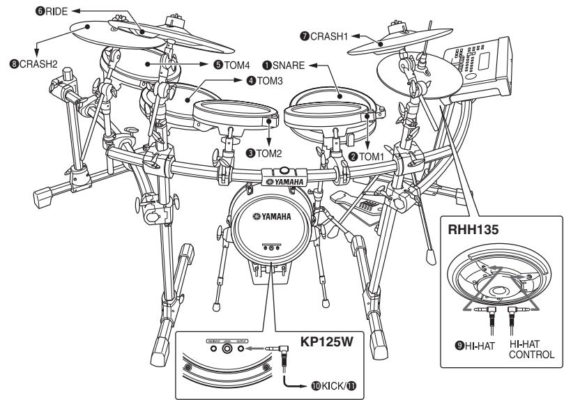
Jacks of the Pads
6 Connect the AC power adaptor to the Drum Trigger Module.
- Make sure the (Standby/On) switch is set to the Standby position (■), then connect the AC power adaptor to the DC IN jack on the rear panel. Twist the cable around the cable clip to prevent the DC plug from inadvertently being disconnected.
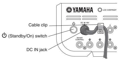
Rear panel of the Drum Trigger Module
- Use the cable bands to bind the cables to the rack as shown at right. If necessary, use the spiral tube.
- Connect the other end of the AC power adaptor to the AC outlet.
- IMPORTANT
- NOTICE
- PRECAUTIONS
- WARNING
- CAUTION
- Checking the contents of each package
- Package 1 [DTP900]
- Package 2 [DTP902]
- Package 3 [Drum Trigger Module DTX900]
- Mounting the Pads and the Drum Trigger Module on the Rack System
- Mount the Pads and the Trigger Module on the Rack System. Then position the Kick Pad and the Hi-Hat.
- Attaching the Cymbal Holder
- Attaching the Tom Pad
- Attaching the Cymbal Pad
- Attaching the Drum Trigger Module
- Assembling the Hi-Hat Stand
- Assembling the Kick Pad
- Assembling the Snare Stand and Snare Pad
- Rear panel of the Drum Trigger Module
Marque : YAMAHA
Modèle : DTX950K
Catégorie : Batterie électronique