
DTX700K - Batterie électronique YAMAHA - Notice d'utilisation et mode d'emploi gratuit
Retrouvez gratuitement la notice de l'appareil DTX700K YAMAHA au format PDF.

| Type de produit | Batterie électronique |
| Marque | YAMAHA |
| Modèle | DTX700K |
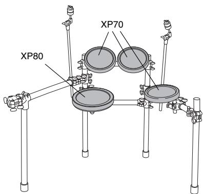
| Composition du kit | RS500 Rack System, DTP700C (cymbales PCY135 x2, hi-hat RHH135, stand HS650A), DTP700P (toms XP70 x3, caisse claire XP80, grosse caisse KP65), module DTX700 |
| Module de contrôle | DTX700 Drum Trigger Module |
| Nombre de pads toms | 3 (XP70) |
| Nombre de pads caisse claire | 1 (XP80) |
| Nombre de pads cymbales | 2 crash/ride (PCY135) + 1 hi-hat (RHH135) |
| Pédale de grosse caisse | KP65 Kick Pad |
| Alimentation | Adaptateur secteur AC (12V+) |
| Consignes de sécurité | Ne pas laisser les enfants monter seuls; serrer tous les boulons; surface plane; ne pas s'asseoir sur le rack; attention aux extrémités pointues; ne pas modifier le produit. |
| Entretien et nettoyage | Nettoyer avec un chiffon doux ou humide; ne pas utiliser de benzène, diluant ou alcool; éviter l'humidité et températures extrêmes. |
| Assemblage | Monter les pads sur le rack à l'aide des boulons de serrage; connecter les câbles. |
| Connexions | Utiliser le câble serpent 9 canaux; brancher les fiches L dans les pads et les fiches droites dans le module. |
| Réglages | Ajuster la hauteur et l'angle des pads en desserrant les boulons un par un. |
| Câbles | Enrouler les câbles autour des clips pour éviter qu'ils ne se débranchent; ne pas plier excessivement. |
| Accessoires fournis | Clé d'accord, bandes de câble, feutres, etc. (voir notice) |
FOIRE AUX QUESTIONS - DTX700K YAMAHA
Questions des utilisateurs sur DTX700K YAMAHA
0 question sur cet appareil. Repondez a celles que vous connaissez ou posez la votre.
Poser une nouvelle question sur cet appareil
Téléchargez la notice de votre Batterie électronique au format PDF gratuitement ! Retrouvez votre notice DTX700K - YAMAHA et reprennez votre appareil électronique en main. Sur cette page sont publiés tous les documents nécessaires à l'utilisation de votre appareil DTX700K de la marque YAMAHA.
MODE D'EMPLOI DTX700K YAMAHA
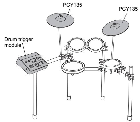
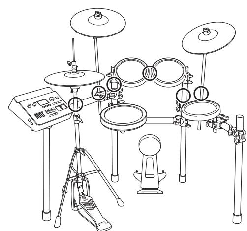
This pamphlet describes the standard procedure for DTX700K assembly.
After assembling the parts and connecting the cords as shown below, you will be ready to turn on the drum trigger module.
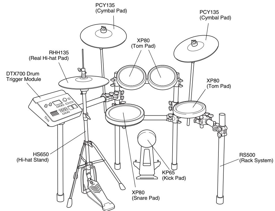
Standard Assembly Example
IMPORTANT
- For assembly, you will require four individual packages - an RS500 Rack System, a DTP700C Pad Set, a DTP700P Pad Set, and a DTX700 Drum Trigger Module.
- This pamphlet describes how to attach the pads and drum trigger module to the RS500 Rack System. Before carrying out the procedures described below, ensure that you have correctly assembled the rack system as described in its assembly manual.
NOTICE
Before starting assembly, lay a drum mat (sold separately) on the floor. Alternatively, before setting up the HS650A Hi-hat Stand and KP65 Kick Pad, you can place the packages' cardboard boxes on the floor to protect it from damage.
PRECAUTIONS
Before using, please read this assembly manual, and use this product in a safe and proper manner.
- Please keep this manual in a safe place for future reference
- Make sure to read the Assembly Manual of the Rack System and the Owner's Manual of the Pad.

WARNING
If this symbol is ignored and the equipment is used improperly, fatal injury to persons or serious damage could occur.
- Do not let small children assemble or set up this product by themselves, or they may be injured. Always assemble this product with adult supervision.
- Be careful with the edges of the Cymbal Holders and the Tom Holders. The sharp holder ends may result in injury.
- Be careful with the edges of the spurs attached to the Kick Pad and foot pedal. The sharp ends may result in injury.
- If this product is used with a Rack System or Cymbal Stand, make sure all bolts are tightened firmly. Also, when adjusting the height or angle, do not suddenly loosen the bolts. Loose bolts may result in the rack overturning or parts dropping, causing injury.
- Always set the product on a flat and solid surface. Placement on a sloping, unstable surface or on steps may result in the product being unstable and subject to overturning.
- When setting up the product, please pay close attention to the handling and setting of cables. Carelessly placed cables may cause the user and others to trip and fall.
- Do not alter the product. Doing so may result in injury or damage/deterioration to the product.
- Do not sit or step on the rack. The rack may overturn or be damaged, resulting in injury.

CAUTION If this symbol is ignored and the equipment is used improperly, there is a danger or injury to persons handling the equipment, and material damage could occur.
- Watch your fingers when adjusting clamps. They may become pinched, resulting in injury.
- Be careful around pipe ends, inside the pipe and screw ends. Metal shavings, etc. may injure your fingers.
- Do not put your hands or feet under the foot pedal or foot switch. They may be pinched, resulting in injury.
- Do not attach acoustic drums to the electronic drum rack. Clamps may be damaged and drums may drop, causing injury.
NOTICE
- Make sure you hold onto the plug, not the cable, when connecting or disconnecting the cable. Also, never place any heavy or sharp objects on the cable. Applying excessive force to the cable may result in damage to the cable, such as the wires being severed, etc.
- Do not step on or place heavy objects on the product. It may result in damage.
- Do not use or keep the product in places with extremely high temperature (places in direct sunlight, close to a heater, in a closed car, etc.) or high humidity (bathroom, outside on a rainy day, etc.). Doing so may result in deformation, discoloration, damage or deterioration.
- When cleaning the product, do not use benzine, thinner or alcohol as it may result in discoloration or deformation. Please wipe with a soft cloth or a damp cloth that has been wrung out thoroughly. If the product is soiled or sticky, use a neutral detergent on a cloth then wipe with a damp cloth that has been wrung out thoroughly to remove any remaining detergent. Also pay close attention so as not to let the water and detergent come into contact with the cushions used in the product; doing so may result in deterioration.
Package 1: DTP700C
PCY135
Cymbal Pad (x2)
□RHH135
Real Hi-hat Pad (x1)
Stand base for the
RHH135 (x)
HS650A
Hi-hat Stand (x1)


Hi-hat clutch for the RHH135 (x1)
Stoppers for the PCY135 (x2)

Tuning key (x1)

Cable band for the RHH135 (x1)
Felts for the PCY135 (x2


9-channel snake cable (x1)
PCY100, PCY135, and PCY155 Owner's Manual (x1)
□ RHH135 Owner's Manual (x1)
Assembly Manual (this pamphlet)
Package 2: DTP700P
XP70
Tom Pad (x3)
XP80
Snare Pad (x1)

KP65
Kick Pad (x1)
Clamp bolts (x4)

XP70 and XP80 Owner's Manual (x1)
KP65 Owner's Manual (x1)
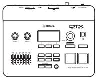
Package 3: DTX700
- DTX700 Drum Module (x1)
Module stand (x1)
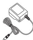
AC power adaptor*

Module stand
fastening screws (x4)

AC power adaptor*
(2)
Module stand
fastening screws (x4)
- May not be included depending on the type of patient.
pending on your particulararea . Please check with
area. Please check with your Yamaha dealer
Mount the pads and the drum trigger module on the rack system.
As described below, mount the pads and the trigger module on the rack system, and then position the kick pad and the hi-hat.
Mounting snare and tom pads
Mounting the snare pad
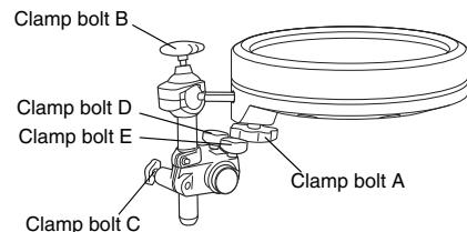
- Attach the clamp bolt to the snare pad and provisionally tighten (by 5 or 6 turns).
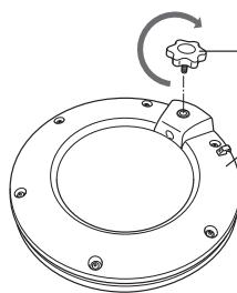
Clamp bolt (to be tightened in the direction shown)
Snare pad (rear side)
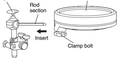
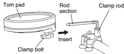
- Mount the snare pad on the rack's clamp rod. As shown below, ensure that the rod section is fully inserted into the pad's mounting hole, and then fully tighten the clamp bolt.
Clamp rod
- If necessary, use clamp bolts A to E to adjust the height and angle of the snare pad. When doing so, be sure to adjust one bolt at a time (i.e., loosen a bolt, adjust the pad, and then retighten before loosening another).
Mounting the tom pad
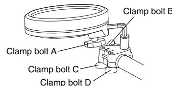
- As with the snare pad, attach the clamp bolt to each of the three tom pads and provisionally tighten (by 5 or 6 turns).
- Mount the three tom pads on the rack's clamp rods. As shown below, ensure that the rod section is fully inserted into each pad's mounting hole, and then fully tighten the clamp bolt.
- If necessary, use clamp bolts A to D to adjust the height and angle of any of the pads. When doing so, be sure to adjust one bolt at a time (i.e., loosen a bolt, adjust the pad, and then retighten before loosening another).
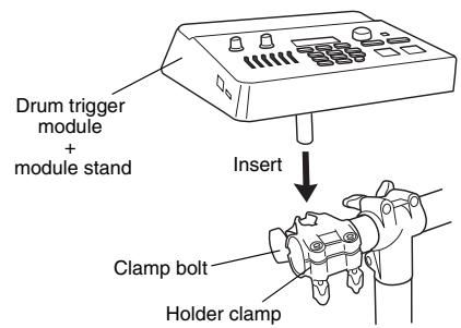
Mounting the drum trigger module and cymbal pads
Mounting the drum trigger module
- Attach the module stand (provided) to the underside of the drum trigger module using the module stand fastening screws.
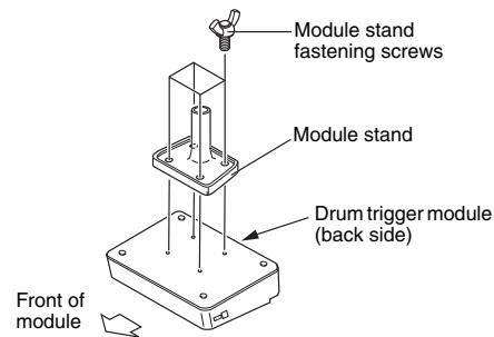
- Place the module stand inside the holder clamp and tighten the clamp bolt to secure in position.
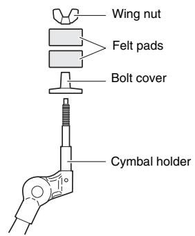
Mounting the cymbal pads
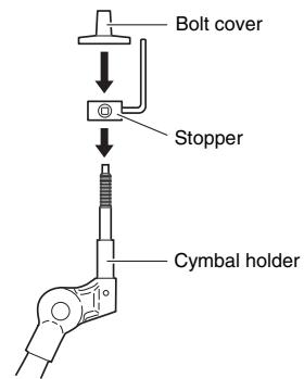
- Using a tuning key, loosen the stopper's key bolt.
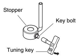
- Remove the wing nut, the two felt pads, and the bolt cover from the cymbal holder.
-
Place the stopper on the cymbal holder.
-
If the key bolt was not sufficiently loosened in Step 1 above, it may not be possible to pass the stopper over the cymbal holder's shaft. In such a case, loosen the key bolt as much as possible without removing it.
-
Replace the bolt cover.
-
When assembling the bolt cover, turn until it no longer rotates.
-
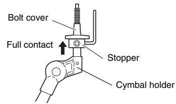
Secure the stopper in place. With the stopper making full contact with the bottom surface of the bolt cover, tighten the stopper's key bolt using a tuning key.
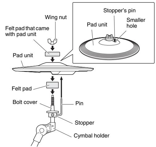
- Place one of the felt pads removed in Step 2 on the cymbal holder.
- Mount the pad unit on the cymbal stand. Lower the pad unit into place with the cymbal holder's shaft passing through the central hole of the cup section. When mounted, the stopper's pin should rest inside the pad unit's smaller hole.
- If you were to play a cymbal pad without the stopper's pin positioned inside the smaller hole, the pad could rotate, causing the cable to be pulled out. It is very important, therefore, to ensure that the stopper is secured as described in Step 5 above.
- Assemble the felt pad that came with your pad unit.
- The second felt pad removed from the cymbal holder in Step 2 above is not required for assembly of your pad unit.
- Tighten the wing nut to secure the pad unit to the cymbal holder.
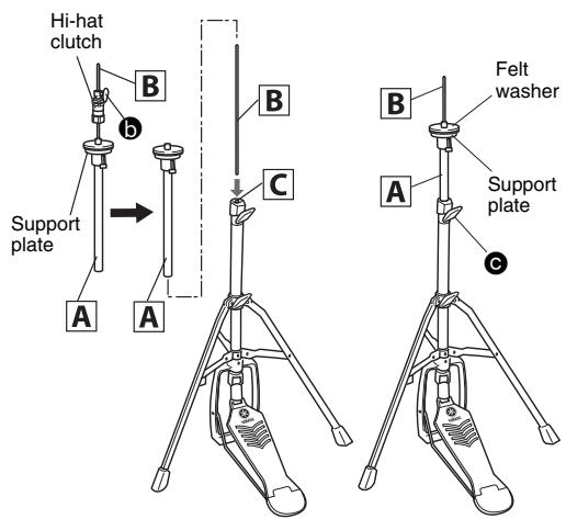
Assembling the hi-hat stand
- If a drum mat (sold separately) is not available, lay a sheet of cardboard on the floor to protect it from scratching.
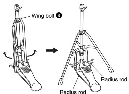
- Loosen the hi-hat stand's wing bolt (3 in the following figure).
- Extend the tripod legs to stabilize the stand. Retighten the wing bolt loosened in Step 2.
- Insert the radius rod into the frame hole as shown below.
- As shown on the right, loosen the wing bolt (6 in the figure) to remove the hi-hat clutch.
- This hi-hat clutch is not used within the standard assembly example shown in this pamphlet. Instead, use the hi-hat clutch that came with your RHH135.
6.Pull out the hi-hat shaft B from the upper pipe A - Screw the hi-hat shaft B into the nut on the lower pipe C.
- Insert the upper pipe A into the hi-hat shaft B from above, and then tighten the wing bolt (C in the figure) with the support plate positioned at the middle area of the hi-hat shaft B.
- Remove the felt washer located above the support plate. It is not used within the standard assembly example shown in this pamphlet.
-
Set up the RHH135 Real Hi-hat Pad.
-
Refer to refer to the Setting Up section of the owner's manual that came with your RHH135.
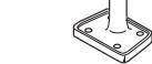
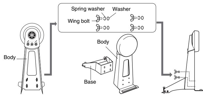
Assembling the kick pad
- If a drum mat (sold separately) is not available, lay a sheet of cardboard on the floor to protect it from scratching.
- Remove the wing bolts, spring washers, and washers from the kick pad frame, and line up each set nearby in the order in which it was removed.
- Join the base section to the frame as shown right, and then secure it in place by assembling the wing bolts, spring washers, and washers removed in the previous step from the base side.
4 Position the hi-hat stand and kick pad as desired, referring to the standard assembly example on the other side. 101E Before starting assembly, lay a drum mat (sold separately) on the floor. Alternatively, you can place the packages' cardboard boxes on the floor under the hi-hat stand and kick pad to protect it from damage.
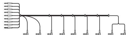
5 Connect the pads to the drum trigger module. As described below, connect the output of each pad to the corresponding trigger input jack on the drum trigger module.
- Insert the 9-channel snake cable's straight plugs into the drum trigger module's trigger input jacks ([1] SNARE) to [9] KICK/10 and [HI-HAT CONTROL]).
- If you are using the standard setup, the stickers on each of the snake cable's plugs will indicate the name of the corresponding pad.
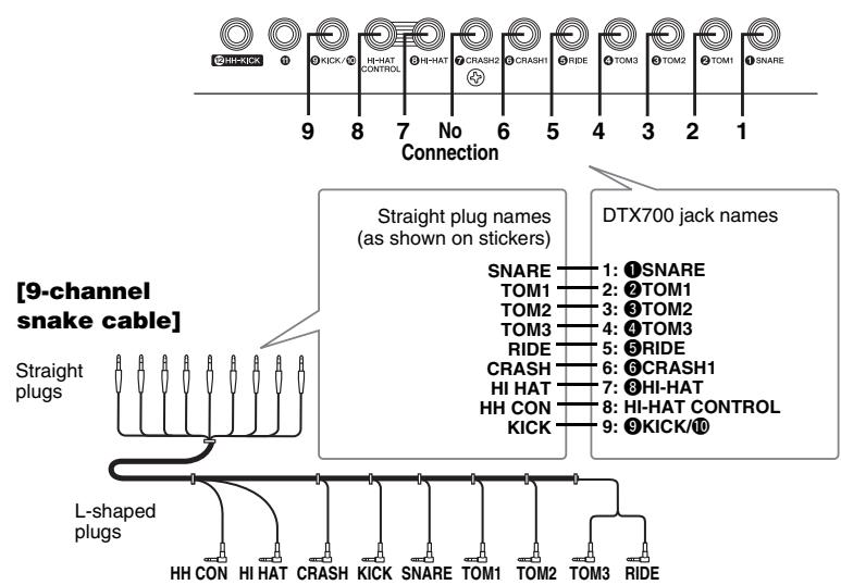
[Drum trigger module's rear panel]
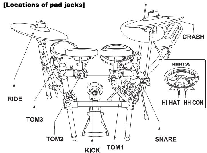
- Plug the 9-channel snake cable's L-shaped plugs into the correct pads.
- In the case of snare and tom pads, wrap the cables around the cable clips to prevent them from being pulled out.

Excessive bending can damage the pad cables. Ensure, therefore, that these cables are not bent at an extreme angle when wrapped around the clips.
6 Connect the drum trigger module to a power supply.
- Insert the power adaptor's DC plug into the 12V+ - connector. Hook the power adaptor's cord around the cord clip to secure it in place.
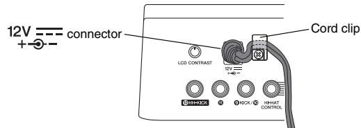
[Drum trigger module's rear panel]
- Use the cable bands to bind the cables to the rack as shown on the right. (O
- Plug the AC power adaptor into an AC wall socket.
This completes the assembly procedure. * For information about tuning the power on/off, checking the actual sound, and other subsequent steps,
refer to the Setting Up section of the owner's manual that came with your drum trigger module.