U2410 - Televizor DELL - Besplatni korisnički priručnik
Pronađite besplatno priručnik za uređaj U2410 DELL u PDF formatu.

Pitanja korisnika o U2410 DELL
0 pitanje o ovom uređaju. Odgovorite na one koje znate ili postavite svoje.
Postavi novo pitanje o ovom uređaju
Preuzmite upute za vaš Televizor u PDF formatu besplatno! Pronađite svoj priručnik U2410 - DELL i uzmite svoju elektroničku napravu natrag u ruke. Na ovoj stranici objavljeni su svi dokumenti potrebni za korištenje vaše naprave. U2410 marke DELL.
KORISNIČKI PRIRUČNIK U2410 DELL
Dell™ U2410 Flat Panel Monitor User's Guide
About Your Monitor
Setting Up the Monitor
Operating the Monitor
Solving Problems
Appendix
Notes, Cautions, and Warnings
Throughout this guide, blocks of text may be accompanied by an icon and printed in bold type or in italic type. These blocks are notes, notices, and cautions, and they are used as follows:

NOTE: A NOTE indicates important information that helps you make better use of your computer.

CAUTION: A CAUTION indicates potential damage to hardware or loess of data if instructions are not followed.

WARNING: A WARNING indicates a potential for property damage, personal injury or death.
Some warnings may appear in alternate formats and may be unaccompanied by an icon. In such cases, the specific presentation of the caution is mandated by regulatory authority.
Information in this document is subject to change without notice. © 2009-2011 Dell Inc. All rights reserved.
Reproduction of these material in any manner whatsoever without the written permission of Dell Inc. is strictly forbidden.
Trademarks used in this text: Dell, the DELL logo are trademarks of Dell Inc; Microsoft and Windows either registered trademarks or trademarks of Microsoft Corporation in the United States and/or other countries.
Other trademarks and trade names may be used in this document to refer to either the entities claiming the marks and names or their products. Dell Inc. disclaims any proprietary interest in trademarks and trade names other than its own.
Model U2410f
May 2011 Rev. A06
Back to Contents Page
About Your Monitor
Dell™ U2410 Flat Panel Monitor User's Guide
Package Contents
Product Features
Identifying Parts and Controls
Monitor Specifications
Universal Serial Bus (USB) Interface
Card Reader Specifications
Plug and Play Capability
LCD monitor Quality and Pixel Policy
Maintenance Guidelines
Package Contents
Your monitor ships with the components shown below. Ensure that you have received all the components and contact Dell if something is missing.

NOTE: Some items may be optional and may not ship with your Monitor. Some features or media may not be available in certain countries.
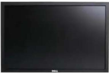 | • Monitor |
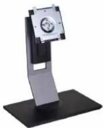 | • Stand |
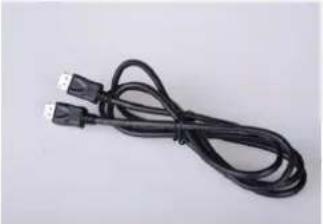
 | • Power Cable |
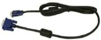 | VGA Cable (attached to the monitor) |
 | DVI Cable |
 | DP Cable |
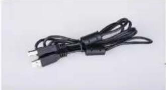 | USB up stream cable (enables the USB ports and card reader on the monitor) |
   | Drivers and Documentation mediaQuick Setup GuideSafety Information |
Product Features
The U2410 flat panel display has an active matrix, thin-film transistor (TFT), liquid crystal display (LCD). The monitor features include:
■ 24-inch (518.4 mm x 324 mm) viewable area display measured diagonally.
■ 1920 x 1200 resolution, plus full-screen support for lower resolutions.
■ Wide viewing angle to allow viewing from a sitting or standing position, or moving side-to-side.
■ Tilt, swivel, rotation and height adjustment capabilities.
■ Removable pedestal and Video Electronics Standards Association (VESA) 100 mm mounting holes for flexible mounting solutions.
■ Plug and Play capability if supported by your system.
■ On-Screen Display (OSD) adjustments for ease of set-up and screen optimization.
■ Software and documentation CD includes an information file (INF), Image color Matching File (ICM), and product documentation.
■ Security lock slot.
Identifying Parts and Features
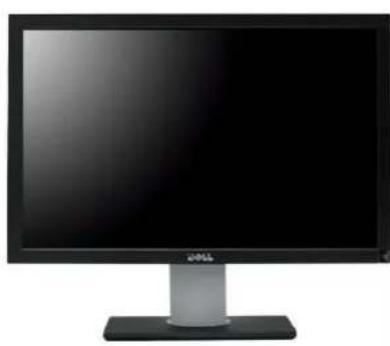
Front View
natural_image
Front view of a black computer monitor with a silver stand (no visible text or symbols)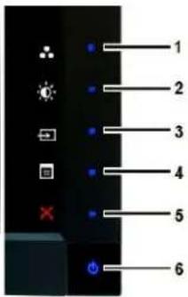
text_image
1 2 3 4 5 6Front View
Control Panel
Label Description
Shortcut keys
1-3
*The default settings are Preset Modes Select, Brightness/Contrast Select and Input Source Select.
1 Preset Modes Select
2 Brightness/Contrast Select
3 Input Source Select
4 OSD Menu Select
5 Exit
6 Power Button (with power light indicator)
NOTE:1\~5 buttons are capacitive touch buttons, which are activated by placing your finger on the blue LED.
Back View
text_image
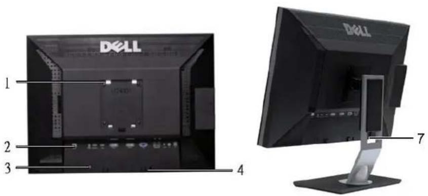
1 2 3 4 7 DELL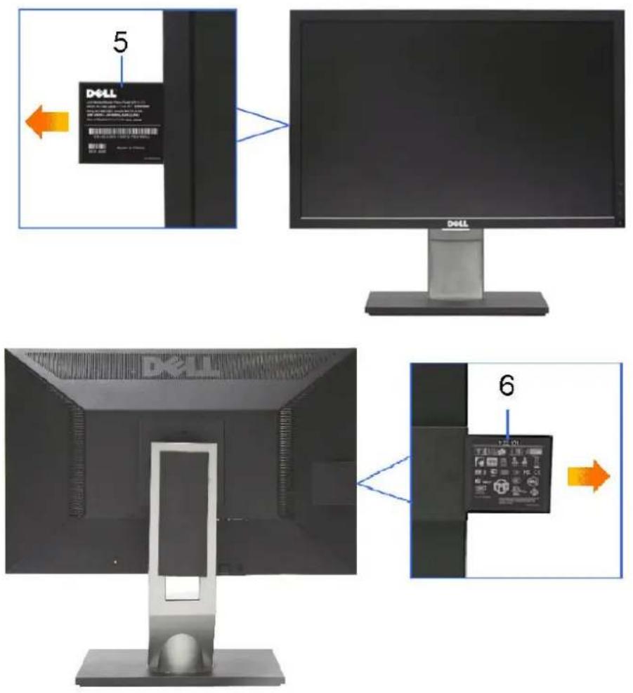
Back View
Back View with monitor stand
| Label | Description/Use | |
| 1 | VESA Mounting Holes (100mm) (Behind attached VESA Plate) | To mount the monitor. |
| 2 | Connectors Label | To indicate the positions and types of connectors. |
| 3 | Security Lock Slot | To help secure your monitor. |
| 4 | Dell Soundbar Mounting Brackets | To attach the optional Dell Soundbar. |
| 5 | Barcode Serial Number Label | To contact Dell for technical support. |
| 6 | Regulatory Rating Label | Lists the regulatory approvals. |
| 7 | Cable Management Slot | To organize cables by placing them through the slot. |
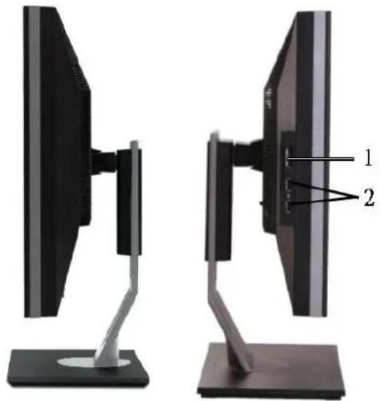
Side View
natural_image
Two views of a computer monitor with labeled parts, showing front and side angles (no text or symbols present)Right View
Left View
Label Description
1 Card Reader. See Card Reader Specifications for more information.
2 USB Down Stream Ports
Bottom View
natural_image
Metal mechanical component with a central circular feature and symmetrical cutouts, mounted on a base (no visible text or symbols)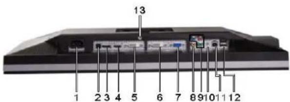
text_image
13 1 2 3 4 5 6 7 8 9 10 11 12Bottom View
Label Description
1 AC Power Cord Connector
2 DC Power Connector for Dell™ Soundbar
3 DisplayPort Connector
4 HDMI Connector
5 DVI Connector-1
6 DVI Connector-2
7 VGA Connector
8 Composite Video Connector
9 Component Video Connectors
10 Audio Out (Support two channel output)
11 USB Upstream Port
12 USB Downstream Port
13 Stand Lock (Use a M3x14 threaded screw to lock stand, screw not provided)
Monitor Specifications
The following sections give you information about the various power management modes and pin assignments for various connectors for your monitor.
Power Management Modes
If you have VESA's DPMS compliance display card or software installed in your computer, the monitor automatically reduces its power consumption when not in use. This is referred to as Power Save Mode. If input from keyboard, mouse or other input devices is detected by the computer, the monitor will automatically "wake up". The following table shows the power consumption and signaling of this automatic power-saving feature:
| VESA Modes | Horizontal Sync | Vertical Sync | Video | Power Indicator | Power Consumption |
| Normal operation (with max luminance, Dell Soundbar and USB active) | Active | Active | Active | Blue | 132 W (Maximum) |
| Normal operation | Active | Active | Active | Blue | 75 W (Typical) |
| Active-off mode | Inactive | Inactive | Blanked | Amber | Less than 1 W |
| Switch off | - | - | - | Off | Less than 1 W |
Activate the computer and wake up the monitor to gain access to the OSD.
NOTE: This monitor is TCO' 03 power management compatible.
NOTE: Zero power consumption in OFF mode can only be achieved by disconnecting the power cable from the monitor.
Pin Assignments
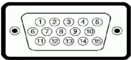
VGA Connector
text_image
①②③④⑤ ⑥⑦⑧⑨⑩ ⑪⑫⑬⑭⑮| Pin Number | 15-pin Side of the Connected Signal Cable |
| 1 | Video-Red |
| 2 | Video-Green |
| 3 | Video-Blue |
| 4 | GND |
| 5 | Self-test |
| 6 | GND-R |
| 7 | GND-G |
| 8 | GND-B |
| 9 | Computer 5V/3.3V |
| 10 | GND-sync |
| 11 | GND |
| 12 | DDC data |
| 13 | H-sync |
| 14 | V-sync |
| 15 | DDC clock |
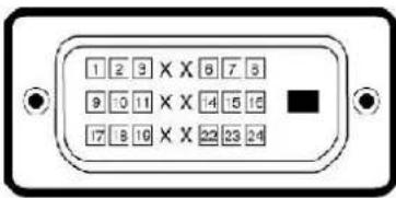
DVI Connector
text_image
1 2 3 × X 6 7 5 9 10 11 × X 4 5 15 17 8 10 × X 23 23 24| Pin Number | 24-pin Side of the Connected Signal Cable |
| 1 | TMDS RX2- |
| 2 | TMDS RX2+ |
| 3 | TMDS Ground |
| 4 | Floating |
| 5 | Floating |
| 6 | DDC Clock |
| 7 | DDC Data |
| 8 | Floating |
| 9 | TMDS RX1- |
| 10 | TMDS RX1+ |
| 11 | TMDS Ground |
| 12 | Floating |
| 13 | Floating |
| 14 | +5V/+3.3V power |
| 15 | Self test |
| 16 | Hot Plug Detect |
| 17 | TMDS RX0- |
| 18 | TMDS RX0+ |
| 19 | TMDS Ground |
| 20 | Floating |
| 21 | Floating |
| 22 | TMDS Ground |
| 23 | TMDS Clock+ |
| 24 | TMDS Clock- |
Composite Video Connector

Luma composite chroma
Component Video Connector


| Pin Number | 3-pin Side of the Connected Signal Cable (Cable not included) |
| 1 | Y (Luminance signal) |
| 2 | Pb (Color differential signal) |
| 3 | Pr (Color differential signal) |
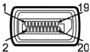
DisplayPort Connector
text_image
1 2 19 20| Pin Number | 20-pin Side of the Connected Signal Cable |
| 1 | ML0(p) |
| 2 | GND |
| 3 | ML0(n) |
| 4 | ML1(p) |
| 5 | GND |
| 6 | ML1(n) |
| 7 | ML2(p) |
| 8 | GND |
| 9 | ML2(n) |
| 10 | ML3(p) |
| 11 | GND |
| 12 | ML3(n) |
| 13 | GND |
| 14 | GND |
| 15 | AUX(p) |
| 16 | GND |
| 17 | AUX(n) |
| 18 | HPD |
| 19 | Re-PWR |
| 20 | PWR |
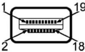
HDMI Connector
text_image
1 19 2 18| Pin Number | 19-pin Side of the Connected Signal Cable |
| 1 | TMDS DATA 2+ |
| 2 | TMDS DATA 2 SHIELD |
| 3 | TMDS DATA 2- |
| 4 | TMDS DATA 1+ |
| 5 | TMDS DATA 1 SHIELD |
| 6 | TMDS DATA 1- |
| 7 | TMDS DATA 0+ |
| 8 | TMDS DATA 0 SHIELD |
| 9 | TMDS DATA 0- |
| 10 | TMDS CLOCK |
| 11 | TMDS CLOCK SHIELD |
| 12 | TMDS CLOCK- |
| 13 | Floating |
| 14 | Floating |
| 15 | DDC CLOCK (SDA) |
| 16 | DDC DATA (SDA) |
| 17 | GROUND |
| 18 | +5V POWER |
| 19 | HOT PLUG DETECT |
Flat Panel Specifications
| Screen type | Active matrix - TFT LCD |
| Panel type | IPS |
| Screen dimensions | 24 inches (24-inch diagonal viewable image size) |
| Preset display area: | |
| Horizontal | 518.4mm (20.41 inches) |
| Vertical | 324.0mm (12.75 inches) |
| Pixel pitch | 0.27mmx0.27mm |
| Viewing angle | 178^ (Vertical) typical, 178^ (Horizontal) typical |
| Luminance output | 400 cd/m^2 (typ) |
| Contrast ratio | 1000:1 (typ), 80,000:1 (Max, Dynamic Contrast on) |
| Faceplate coating | Antiglare with hard-coating 3H |
| Backlight | 7 CCFL U-type system |
| Response Time | 6ms panel typical (Grey to Grey) |
| Color Gamut | 110 % (typ.) |
* U2410 Color Gamut (Typical) is based on CIE1976 (110%) and CIE1931 (102%)
Resolution
| Horizontal scan range | 30 kHz to 81 kHz (automatic) |
| Vertical scan range | 56 Hz to 76 Hz |
| Maximum resolution | 1920 x 1200 at 60 Hz |
Video Supported Modes
| Video display capabilities (DVI playback) | 480i/480p/576i/576p/720p/1080i/1080p (Supports HDCP) |
| Video display capabilities (Composite playback) | NTSC/PAL |
| Video display capabilities (HDMI playback) | 480i/480p/576i/576p/720p/1080i/1080p |
| Video display capabilities (Component playback) | 480i/480p/576i/576p/720p/1080i/1080p |
Preset Display Modes
The following table lists the preset modes for which Dell guarantees image size and centering:
| Display Mode | Horizontal Frequency (kHz) | Vertical Frequency (Hz) | Pixel Clock (MHz) | Sync Polarity (Horizontal/Vertical) |
| VGA, 720 × 400 | 31.5 | 70.1 | 28.3 | -/+ |
| VGA, 640 × 480 | 31.5 | 59.9 | 25.2 | -/- |
| VESA, 640 × 480 | 37.5 | 75.0 | 31.5 | -/- |
| VESA, 800 × 600 | 37.9 | 60.3 | 40.0 | +/+ |
| VESA, 800 × 600 | 46.9 | 75.0 | 49.5 | +/+ |
| VESA, 1024 × 768 | 48.4 | 60.0 | 65.0 | -/- |
| VESA, 1024 × 768 | 60.0 | 75.0 | 78.8 | +/+ |
| VESA, 1152 × 864 | 67.5 | 75.0 | 108.0 | +/+ |
| VESA, 1280 × 1024 | 64.0 | 60.0 | 108.0 | +/+ |
| VESA, 1280 × 1024 | 80.0 | 75.0 | 135.0 | +/+ |
| VESA, 1600 × 1200 | 75.0 | 60.0 | 162.0 | +/+ |
| VESA, 1920 × 1200 | 74.5 | 60.0 | 154.0 | +/- |
Electrical
The following table lists the electrical specification:
| Video input signals | Analog RGB, 0.7 Volts +/-5%, 75 ohm input impedance Digital DVI-D TMDS, 600mV for each differential line,50 ohm input impedance HDMI, 600mV for each differential line,100 ohm input impedance per differential pair DisplayPort, 600mV for each differential line,100 ohm input impedance per differential pair Composite, 1 volt(p-p), 75 ohm input impedance Component: Y, Pb, Pr are all 0.5~1volt(p-p), 75 ohm input impedance |
| Synchronization input signals | separate horizontal and vertical, 3.3V CMOS or 5V TTL level, positive or negative sync. SOG (Sync on green) |
| AC input voltage/frequency/current | 100 to 240 VAC/50 or 60 Hz ± 3 Hz/2.0 A (Max.) |
| Inrush current | 120V: 40A (Max.) 240V: 80A (Max.) |
Physical Characteristics
The following table lists the physical characteristics:
| Connector type | VGA: Blue ConnectorDVI-D: White ConnectorDisplayPort: Black ConnectorCompositeComponentHDMI |
| Signal cable type | D-sub: Detachable, Analog, 15pin, shipped attached to the monitorDVI-D: Detachable, Digital, 24pin, shipped detached from the monitorDisplayPort: Detachable, Digital, 20pin, shipped detached from the monitorCompositeComponentHDMI |
| Dimensions (with stand) | |
| Height (Compressed) | 393.0mm (15.47 inches) |
| Height (Extended) | 493.0 mm (19.40 inches) |
| Width | 559.7 mm (22.03 inches) |
| Depth | 201.5 mm (7.93 inches) |
| Dimensions (without stand) | |
| Height | 365.1mm (14.37 inches) |
| Width | 559.7 mm (22.03 inches) |
| Depth | 81.0 mm (3.18 inches) |
| Stand Dimensions | |
| Height (Compressed) | 340.7 mm (13.41 inches) |
| Height (Extended) | 370.7 mm (14.59 inches) |
| Width | 309.7 mm (12.19 inches) |
| Depth | 201.5 mm (7.93 inches) |
| Weight | |
| Weight with packaging | 11.60 kg (25.64 lb) |
| Weight with stand assembly and cables | 9.57 kg (19.93 lb) |
| Weight without stand assembly(For wall mount or VESA mount considerations - no cables) | 6.50 kg (14.30 lb) |
| Weight of stand assembly | 2.41 kg (5.30 lb) |
Environmental
The following table lists the environmental limitation:
Temperature
| Operating | 0° to 40°C (32° to 104°F) |
| Non-Operating | Storage: -20° to 60°C (-4° to 140°F)Shipping: -20° to 60°C(-4° to 140°F) |
Humidity
| Operating | 10% to 80% (noncondensing) |
| Non-Operating | Storage: 5% to 90% (noncondensing)Shipping: 5% to 90%(noncondensing) |
| Altitude | |
| Operating | 3,657.6 m (12,000 ft) max |
| Non-Operating | 12,192 m (40,000 ft) max |
| Thermal dissipation | 375 BTU/hour (maximum)195 BTU/hour (typical) |
Universal Serial Bus (USB) Interface
This monitor supports High-Speed Certified USB 2.0 interface.
| Transfer speed | Data Rate | Power Consumption |
| High speed | 480 Mbps | 2.5W (Max., each port) |
| Full speed | 12 Mbps | 2.5W (Max., each port) |
| Low speed | 1.5 Mbps | 2.5W (Max., each port) |
USB Upstream Connector
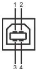
| Pin Number | 4-pin Side of the connector |
| 1 | DMU |
| 2 | VCC |
| 3 | DPU |
| 4 | GND |
USB Downstream Connector
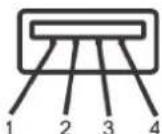
| Pin Number | 4-Pin Side of the Signal Cable |
| 1 | VCC |
| 2 | DMD |
| 3 | DPD |
| 4 | GND |
USB Ports
• 1 upstream - rear
• 4 downstream - 2 on rear; 2 on left side
NOTE: The monitor's 2.0 USB interface functions only if the computer is USB 2.0 compatible.
NOTE: The monitor's USB interface works only when the monitor is on or in power save mode. If you switch the monitor off and then switch it on, the attached peripherals may take a few seconds to resume normal functionality.
Card Reader Specifications
Overview
- The Flash Memory Card Reader is a USB storage device that allows users to read and write information from and into the memory card.
- The Flash Memory Card Reader is automatically recognized by Microsoft® Windows® 2000, Windows® XP, Windows® Vista and Windows® 7.
- Once installed and recognized, each separate memory card (slot) appears as a separate drive/drive letter.
- All standard file operations (copy, delete, drag-and-drop, etc.) can be performed with this drive.
Features
The Flash Memory Card Reader has the following features:
- Supports Microsoft® Windows® 2000, Windows® XP, Windows® Vista and Windows® 7 operating systems
• No Microsoft® Windows® 9X support from Dell
• Mass Storage Class device (No drivers are required under Microsoft® Windows® 2000, Windows® XP, Windows® Vista and Windows® 7) - USB-IF certification
• Supports various memory card media
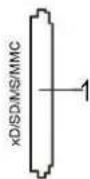
The following table lists the memory cards supported:
| Slot Number | Flash memory cards type |
| 1 | xD-Picture CardMemory Stick Card (MS)/High Speed Memory Stick (HSMS)/Memory Stick Pro Card (MS PRO)/Memory Stick Duo (with Adapter)Secure Digital Card (SD)/Mini Secure Digital (with Adapter)/TransFlash Card (with Adapter)MultiMedia Card (MMC)/Reduced Size MultiMedia Card (with Adapter) |
Maximum Card Capacity Supported by the U2410 card reader
| Card type | Support Specification | Memory Card Spec Version | Support Maximum Capacity by Spec | U2410 |
| MS | Memory Stick Standard Format Specification | 1.43 | 128MB | Supported |
| MSPRO | Memory Stick Pro Standard Format Specifications | 1.02 | 32GB | Supported |
| MSDuo | Memory Stick Duo Standard Format Specifications | 1.10 | 128MB/32GB | Supported |
| MSDuo-HG | Memory Stick Duo Standard Format Specifications | 1.01 | 32GB | Supported |
| xD | xD Picture Card Specification | 1.2 | 2GB | Supported |
| SD | SD Memory Card Specifications | 2.0 | 32GB | Supported |
| MMC | MultiMedia Card System Specification | 4.2 | 32GB | Supported |
NOTE: MSPRO includes MSPRO Duo and MS Micro.
NOTE: xD includes TypeM and TypeH.
NOTE: SD includes HS-SD, MiniSD and SD Micro. SD v2.0 spec includes SDHC.
NOTE: MMC includes MMCPlus, RS-MMC, MMC Mobile and MMC micro.
General
Connection type USB 2.0 High Speed Device (USB Full Speed Device compatible)
Supported OS Microsoft® Windows® 2000, Windows® XP, Windows® Vista and Windows® 7
Performance
Transfer Speed
Read: 480 Mb/s (max.)
Write: 480 Mb/s (max.)
Plug and Play Capability
You can install the monitor in any Plug and Play-compatible system. The monitor automatically provides the computer system with its Extended Display Identification Data (EDID) using Display Data Channel (DDC) protocols so the system can configure itself and optimize the monitor settings. If required, the user can select different settings, but in most cases monitor installation is automatic.
LCD monitor Quality and Pixel Policy
During the LCD Monitor manufacturing process, it is not uncommon for one or more pixels to become fixed in an unchanging state which are hard to see and do not affect the display quality or usability. For more information on Dell Monitor Quality and Pixel Policy, see Dell Support site at: support.dell.com.
Maintenance Guidelines
Caring for Your Monitor

WARNING: Read and follow the Safety Instructions before cleaning the monitor.

WARNING: Before cleaning the monitor, unplug the monitor from the electrical outlet.
For best practices, follow the instructions in the list below while unpacking, cleaning, or handling your monitor:
- To clean your antistatic screen, lightly dampen a soft, clean cloth with water. If possible, use a special screen-cleaning tissue or solution suitable for the antistatic coating. Do not use benzene, thinner, ammonia, abrasive cleaners, or compressed air.
- Use a lightly-dampened, warm cloth to clean the plastics. Avoid using detergent of any kind as some detergents leave a milky film on the plastics.
- Handle your monitor with care as dark-colored monitors may scratch and show white scuff marks more than lighter-colored monitors.
Back to Contents Page
Back to Contents Page
Appendix
Dell™ U2410 Flat Panel Monitor User's Guide
Safety Instructions
FCC Notice (U.S. Only) and Other Regulatory Information
Contacting Dell
WARNING: Safety Instructions

WARNING: Use of controls, adjustments, or procedures other than those specified in this documentation may result in exposure to shock, electrical hazards, and/or mechanical hazards.
For information on safety instructions, see the Safety Information.
FCC Notice (U.S. Only) and Other Regulatory Information
For FCC notices and other regulatory information, see the regulatory compliance website located at www.dell.com/regulatory_compliance.
Contacting Dell
To contact Dell electronically, you can access the following websites and by phone:
- For support through the web, go to support.dell.com.
• For customers in the United States, call 800-WWW-DELL (800-999-3355).

NOTE: If you do not have an active Internet connection, you can find contact information on your purchase invoice, packing slip, bill, or Dell product catalog.
Dell provides several online and telephone-based support and service options. Availability varies by country and product, and some services may not be available in your area. To contact Dell for sales, technical support, or customer service issues:
- Visit support.dell.com.
- Verify your country or region in the Choose A Country/Region drop-down menu at the bottom of the page.
- Click Contact Us on the left side of the page.
- Select the appropriate service or support link based on your need.
- Choose the method of contacting Dell that is convenient for you.
Back to Contents Page
Back to Contents Page
Setting Up Your Monitor
Dell™ U2410 Flat Panel Monitor
If you have a Dell™ desktop or a Dell™ portable computer with internet access
-
Go to http://support.dell.com, enter your service tag, and download the latest driver for your graphics card.
-
After installing the drivers for your Graphics Adapter, attempt to set the resolution to 1920 x 1200 again.
NOTE: If you are unable to set the resolution to 1920 x 1200, please contact Dell™ to inquire about a Graphics Adapter that supports these resolutions.
Back to Contents Page
Back to Contents Page
Setting Up Your Monitor
Dell™ U2410 Flat Panel Monitor
If you have non Dell™ desktop, portable computer, or graphic card
- Right-click on the desktop and click Properties.
- Select the Settings tab.
- Select Advanced.
- Identify your graphics controller supplier from the description at the top of the window (e.g. NVIDIA, ATI, Intel etc.).
- Please refer to the graphic card provider website for updated driver (for example, http://www. ATI.com OR http://www.NVIDIA.com)
- After installing the drivers for your Graphics Adapter, attempt to set the resolution to 1920 x 1200 again.
NOTE: If you are unable to set the resolution to 1920 x 1200, please contact the manufacturer of your computer or consider purchasing a graphics adapter that will support the video resolution of 1920 x 1200.
Back to Contents Page
Operating the Monitor
Dell™ U2410 Flat Panel Monitor User's Guide
Using the Front Panel Controls
Using the On-Screen Display (OSD) Menu
Setting the Maximum Resolution
Using the Dell Soundbar (Optional)
Using the Tilt, Swivel and Vertical Extension
Rotating the monitor
Adjusting the Rotation Display Settings of Your System
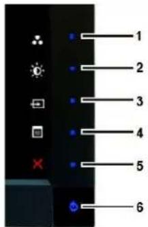
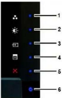
Using the Front Panel
Use the buttons on the front of the monitor to adjust the image settings. 1\~5 are capacitive touch sensor keys, activated by placing the finger on the Blue LED button.
text_image
Camera menu interface with labeled buttons and icons for display settings| 1-3 | Shortcut keys | Use this key for direct access to the control menu that you define in the personalize menu.For example, use the second shortcut key to activate Brightness/Contrast adjustment.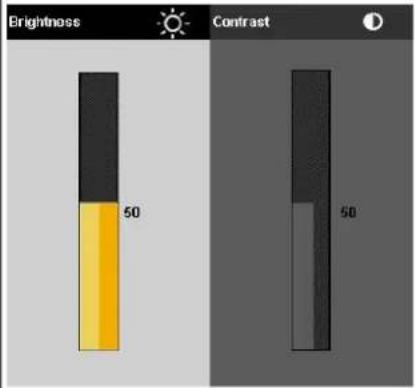 *The default settings are Preset Modes Select, Brightness/Contrast Select and Input Source Select. *The default settings are Preset Modes Select, Brightness/Contrast Select and Input Source Select. |
| 1 | [Preset Modes Select] | Use this button to select different image modes on your monitor. |
| 2 | [Brightness/Contrast] | Use this button for direct access to the "Brightness/Contrast" control menu. |
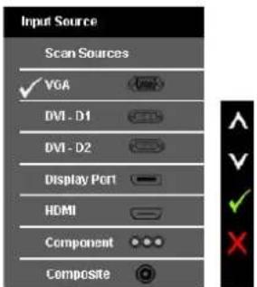
| 3 | [Input Source Select] | Use Input Source Select button to select between different video signals that may be connected to your monitor.VGA inputDVI-D 1 inputDVI-D 2 inputDisplayPort input |
• HDMI input
- Component video input
• Composite video input
Displays the source selection bar. Touch √ and ▲ buttons to move between the setting options and Touch √ to select the i source you want.
text_image
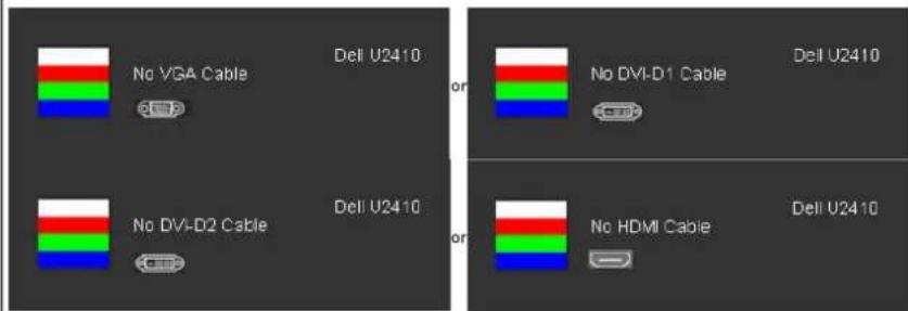
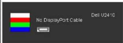
Input Source Scan Sources ✓ VGA DVI - D1 DVI - D2 Display Port HDMI Component CompositeIf VGA or DVI-D or DisplayPort or HDMI input is selected and all VGA and DVI-D and DisplayPort and HDMI cables are not connected floating dialog box as shown below appears.
text_image
Deli U2410 No VGA Cable Deli U2410 or No DVI-D1 Cable Deli U2410 No DVI-D2 Cable Deli U2410 or No HDMI Cable Deli U2410or
text_image
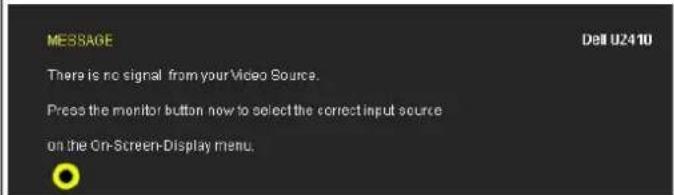
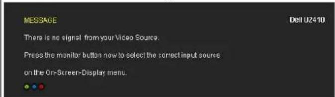
No DisplayPort Cable Dell U2410If either Composite, or Component input is selected and the cables are not connected or the video source is turned off, the sc not have an image. If any button is Touched (except power button), the monitor displays the following message:
text_image
MESSAGE There is no signal from your Video Source. Press the monitor button now to select the correct input source on the On-Screen-Display menu. Dell U2410or
text_image
MESSAGE There is no signal from your Video Source. Press the monitor button now to select the correct input source on the On-Screen-Display menu.| 5 | × Exit | Use this key to exit the OSD menu. |
| 6 | Power button(with power light indicator) | Use the power button to turn the monitor on and off.The Blue LED indicates the monitor is on and fully functional. An amber LED indicates DPMS power save mode. |
Using the OSD Menu
NOTE: If you change the settings and then either proceed to another menu, or exit the OSD menu, the monitor automatically saves the changes. The changes are also saved if you change the settings and then wait for the OSD menu to disappear.

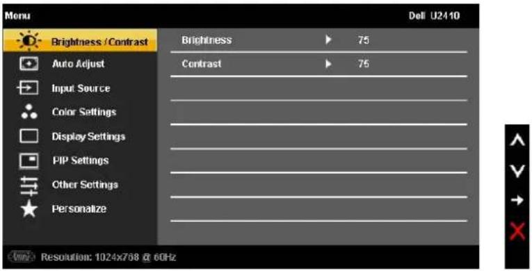
- Touch ☐ to launch the OSD menu and display the main menu.
Main Menu for Analog (VGA) Input
text_image
Menu Brightness / Contrast Auto Adjust Input Source Color Settings Display Settings PIP Settings Other Settings Personalize Brightness Contrast 75 75 Resolution: 1024x768 @ 60HzOr
Main Menu for non Analog (non VGA) Input
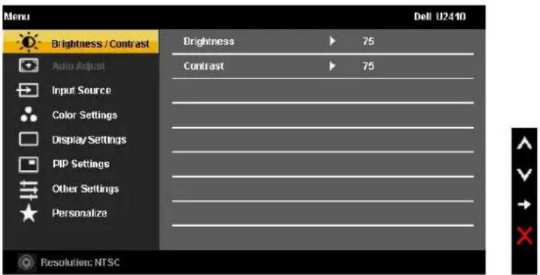
text_image
Menu Brightness / Contrast Auto Adjust Input Source Color Settings Display Settings PIP Settings Other Settings Personalize Brightness ▶ 75 Contrast ▶ 75 Resolution: NTSCNOTE: Auto Adjust is only available when you are using the analog (VGA) connector.
- Touch the √ and ▲ buttons to move between the setting options. As you move from one icon to another, the option name is highlighted. See the table for a complete list of all the options available for the monitor.
- Touch the √ button once to activate the highlighted option.
- Touch V and ▲ button to select the desired parameter.
- Touch √ to enter the slide bar and then use the √ and ▲ buttons, according to the indicators on the menu, to make your changes.
| Icon | Menu and Submenus | Description |
| Brightness/Contrast | Allows you to adjust the brightness and contrast.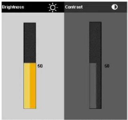 | |
| Brightness | Brightness adjusts the luminance of the backlight.Touch the ▲ button to increase brightness and Touch the ∨ button to decrease brightness (min 0 ~ max 100). | |
| Contrast | Adjust Brightness first, and then adjust Contrast only if further adjustment is necessary.Touch the ▲ button to increase contrast and Touch the ∨ button to decrease contrast (min 0 ~ max 100).The Contrast function adjusts the degree of difference between the darkest and lightest areas on the monitor scre | |
| Back | Touch ↩ to go back to the main menu. | |
| Auto Adjust | 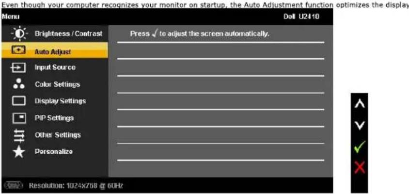  NOTE: In most cases, Auto Adjust produces the best image for your configuration. This option is only available wh connector. NOTE: In most cases, Auto Adjust produces the best image for your configuration. This option is only available wh connector. | |
| Input Source | The Input Source menu is to select between different video signals that may be connected to your monitor. |
Brightness adjusts the luminance of the backlight.
Touch the ▲ button to increase brightness and Touch the √ button to decrease brightness (min 0 \~ max 100).
Adjust Brightness first, and then adjust Contrast only if further adjustment is necessary. Touch the ▲ button to increase contrast and Touch the ▼ button to decrease contrast (min 0 \~ max 100). The Contrast function adjusts the degree of difference between the darkest and lightest areas on the monitor scre
Touch ↻ to go back to the main menu.
The Input Source menu is to select between different video signals that may be connected to your monitor.
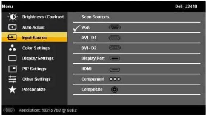 | |||
| Scan Sources | Scan for Sources, touch √ to scan for available input signals. | ||
| VGA | Select VGA input when you are using the analog (VGA) connector. Touch √ to select the VGA input source. | ||
| DVI-D 1 & 2 | Select DVI-D input when you are using the Digital (DVI) connector. Touch √ to select the DVI input source. | ||
| DisplayPort | Select DisplayPort input when you are using DisplayPort connector. Touch √ to select the DisplayPort input source. | ||
| HDMI | Select HDMI input when you are using HDMI connector. Touch √ to select the HDMI input source. | ||
| Component | Select Component input when you are using component video connector. Touch √ to select the component input source. | ||
| Composite | Select Composite input when you are using composite video connector. Touch √ to select the composite input source. | ||
| Back | Touch ⇌ to go back to the main menu. | ||
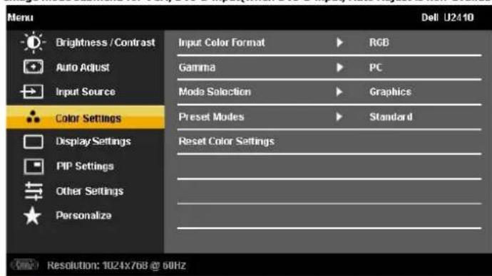
| Color Settings | Allows you to set the image mode and color format. | ||
| Image mode submenu for VGA/DVI-D input/when DVI-D input. Auto Adjust is non-available) | Imag | ||
 | (AADH) or (5384) | ||
| Input Color Format | NOTE: Image modes are different between the VGA/DVI-D and Video inputs. Choose the RGB option if monitor is connected to a computer or a DVD using a VGA or DVI cable. Choose the YPbPr output setting is not RGB. | ||
| Gamma | Allows you to set the color mode to PC or MAC. | ||
| Mode Selection | Allows you to set the display mode to Graphics or Video. If your computer is connected to your monitor, choose Graph | ||
| Preset modes | |||
| VGA/DVI-D1/ DVD-D2/HDMI/DP input | |
| Standard | Mode suitable for desktop applications. |
| Multimedia | Mode for multimedia applications, eg video playback. |
| Game | Mode suitable for gaming applications. Use this mode for minimal input lag. |
| Warm | Select warm mode to obtain a red tint. This color setting is typically used for color-intensive applications (photograph) |
| Cool | Select cool mode to obtain a bluish tint. This color setting is typically used for text based applications (spreadsheets |
| Adobe RGB | This mode is compatible with Adobe RGB (96 % coverage). |
| sRGB | Emulates 72 % NTSC color. |
| Custom Color | This mode allows users to have full control of the monitor's advance 6-axis color adjustments. |
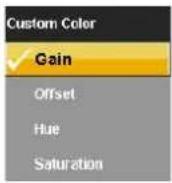 [Y004] [Y004] | |
| Use the √ or ∧ button to select the Gain, Offset, Hue, Saturation. | |
| Gain: Select it to adjust input RGB signal gain level (default value are 100). | |
| Offset: Select it to adjust RGB black-level offset value (default value are 50) to control your monitor base color. | |
| Hue: Select it to adjust RGBCMY hue value individually. | |
| Saturation: Select it to adjust RGBCMY saturation value individually. | |
| Video input | Image mode submenu for Video input |
| Menu Dell U2110 | |
| Brightness / Contrast Input Color Format ▶ RGB | |
| Auto Adjust Gamma ▶ PC | |
| Input Source Mode Selection ▶ Video | |
| Color Settings Preset Modes ▶ Movie | |
| Display Settings Hue ▶ 50 | |
| PIP Settings Saturation ▶ 50 | |
| Other Settings Reset Color Settings | |
| Personalize | |
| Resolution NTSC | |
| Movie | Mode suitable for movie playback. |
| Game | Mode suitable for game applications. |
| Nature | Mode suitable for nature scenes. |
| xvMode | Mode suitable for xvYCC compliance source. |
| Hue | This feature can make the video image color shift from green to purple. Use this feature to adjust the skin tone. Use √ increases the green hue in the image ∧ increases the purple hue in the image |
| NOTE: Hue adjustment is only available for video input. | |
| Saturation | Allows you to adjust the color saturation of the video image. Use √ or ∧ button to adjust the saturation from '0' √ makes video image looks monochrome ∧ makes video image looks colorful |
| NOTE: Saturation adjustment is only available for video input. | |
| Reset Color Settings | Returns your monitor color settings to those that were set at the time of manufacture. |
| Menu | Dell U2110 | ||
| Brightness / Contrast | Input Color Format | RGB | |
| Auto Adjust | Gamma | PC | |
| Input Source | Mode Selection | Video | |
| Color Settings | Preset Modes | Movie | |
| Display Settings | Hue | 50 | |
| PIP Settings | Saturation | 50 | |
| Other Settings | Reset Color Settings | ||
| Personalize | |||
| Back | Touch → to go back to the main menu. | |
| Display Settings | Use the Display Settings to adjust image. | |
| Menu Dell U2410 Brightness / Contrast Wide Mode ▶ Fill Auto Adjust Horizontal Position ▶ 50 Input Source Vertical Position ▶ 50 Color Settings Sharpness ▶ 50 Display Settings Noise Reduction ▶ Medium PIP Settings Zoom ▶ 0 Other Settings Pixel Clock ▶ 50 Personalize Phase ▶ 54 Dynamic Contrast ▶ On Display Info Reset Display Settings Resolution: 1024x768 @ 60Hz | ||
| Wide Mode | Adjusts the image ratio as 1:1, Aspect or full screen. NOTE: Wide Mode adjustment is not required at optimal preset resolution 1920 x 1200. | |
| Horizontal Position | Use the √ and ▲ buttons to adjust image left and right. Minimum is '0' (-). Maximum is '100' (+). | |
| Vertical Position | Use the √ and ▲ buttons to adjust image up and down. Minimum is '0' (-). Maximum is '100' (+). | |
| Sharpness | This feature can make the image look sharper or softer. Use √ or ▲ to adjust the sharpness from '0' to '100'. | |
| Noise Reduction | Improve the motion picture quality by reducing noise on image edge. | |
| Zoom | Use the Zoom function to zoom in to specific area of interest. Using the √ and ▲ keys to zoom in and out. | |
| Pixel Clock | The Phase and Pixel Clock adjustments allow you to adjust your monitor to your preference. Use the √ and ▲ buttons to adjust for best image quality. | |
| Phase | If satisfactory results are not obtained using the Phase adjustment, use the Pixel Clock (coarse) adjustment and th NOTE: Pixel Clock and Phase Adjustments are only available for "VGA" input. | |
| Dynamic Contrast | Allows you to increase the level of contrast to provide sharper and more detailed image quality. | |
| Display Info | Displays the monitor's current settings. | |
| Reset Display Settings | Select this option to restore default display settings. | |
| Back | Touch → to go back to the main menu. | |
| PIP Settings | This function brings up a window displaying image from another input source. | |
| PIP/PBP submenu when PIP/PBP OFF (main source is VGA/DVI-D input) PIP/ |
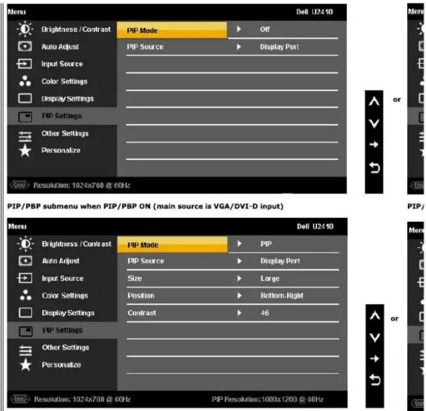
text_image
Menu Dell U2410 Brightness / Contrast PIP Mode Off Auto Adjust PIP Source Display Port Input Source Color Settings Display Settings PIP Settings Other Settings Personalize Resolution: 1024x768 @ 60Hz PIP/PBP submenu when PIP/PBP ON (main source is VGA/DVI-D input) Menu Dell U2410 Brightness / Contrast PIP Mode PIP Auto Adjust PIP Source Display Port Input Source Size Large Color Settings Position Bottom-Right Display Settings Contrast 46 PIP Settings Other Settings Personalize Resolution: 1024x768 @ 60Hz PIP Resolution:1000x1200 @ 60HzPIP Mode
NOTE: When using DVI source, the Auto adjustment is not available.
There are two modes: Picture in Picture (PIP) and Picture by Picture (PBP)
Use √ and ∧ to browse and √ to select "Off", "PIP" or "PBP".
When PIP/PBP activated
When PIP/PBP is activated, select "Swap" to exchange the input source for the main screen and PIP/PBP window.
PIP Source
Select an input signal for PIP/PBP. (VGA/DVI-D 1/DVI-D 2/DP (DisplayPort)/HDMI/Composite/Component)
Use √ and ∧ to browse and √ to select.
Size
Select PIP window size.
Use √ and ∧ to browse and √ to select.
Position
Select PIP window position.
Use √ and ∧ to browse and √ to select.
Contrast
Adjust the contrast level of the picture in PIP/PBP Mode.
V reduces the contrast
^ increases the contrast
Hue
This function shifts the color of PIP/PBP image to green or purple. This is used to adjust for desired flesh tone color.
shifts image color towards green
^ shifts image color towards purple
Saturation
Adjust the color saturation of PIP/PBP image.
V makes the image look more monochrome
^ makes the image look more colorful
Back

to go back to the main menu.
| ≡ | Other Settings | Select this option to adjust the settings of the OSD, such as, the languages of the OSD, the amount of time the me.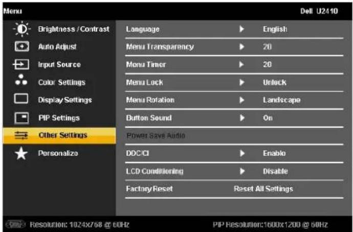 [CX42]Language option to set the OSD display to one of eight languages (English, Espanol, Francais, Deutsch, Japanese,E [CX42]Language option to set the OSD display to one of eight languages (English, Espanol, Francais, Deutsch, Japanese,E |
| Language | ||
| Menu Transparency | Allows you to adjust the OSD background from opaque to transparent. | |
| Menu Timer | OSD Hold Time: Sets the length of time the OSD will remain active after the last time you Touched a button.Use the √ and ∧ buttons to adjust the slider in 5 second increments, from 5 to 60 seconds. | |
| Menu Lock | Controls user access to adjustments. When lock, no user adjustments are allowed. All buttons are locked. To unloc button) for 15 sec.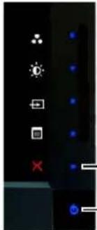 - Exit button-Power buttonNOTE: Menu lock can also be activated by touching the Exit button (located above power button) for 15 sec. Touch - Exit button-Power buttonNOTE: Menu lock can also be activated by touching the Exit button (located above power button) for 15 sec. Touch | |
| Menu Rotation | Rotates the OSD by 90 degrees counter-clockwise. Your can adjust the menu according to your rotating your monit | |
| Button Sound | NOTE: Menu Rotation is not available when PIP/PBP is on.The monitor beeps everytime a new option is selected in the menu. This button enables or disables the sound. | |
| Power Save Audio | Turns the Audio Power on or off during power save mode. | |
| DDC/CI | DDC/CI (Display Data Channel/Command Interface) allows your monitor parameters (brightness, color balance etc) can disable this feature by selecting "Disable".Enable this feature for best user experience and optimum performance of your monitor. | |
| LCD Conditioning | MESSAGE Dell U2410The function of adjusting display settings using PC application will be disabled.Do you wish to disable DDC/C function?NoYesIf an image appears to be stuck on the monitor, select LCD Conditioning to help eliminate any image retention. Use several hours. Severe cases of image retention are known as burn-in, the LCD Conditioning feature does not remo | |
| MESSAGE Dell U2410The feature will help reduce minor cases of image retention.Depending on the degree of image retention, the program may take some time to run.Do you want to continue?NoYesLCD Conditioning is currently in progress, press any button on the monitor to terminate LCD Conditioning at any time. | ||
| Factory ResetBack | Reset all OSD settings to the factory preset values.Touch ➔ to go back to the main menu. | |
| ★ | Personalize | There are three shortcut keys on the front panel. Select one control menu for each shortcut key to allow direct acce |
| Menu Dell U2410Brightness / Contrast Shortcut Key 1 Preset ModesAuto Adjust Shortcut Key 2 Brightness/ContrastInput Source Shortcut Key 2 Input SourceColor SettingsDisplay SettingsPIP SettingsOther SettingsPersonalizeResolution: 1024x768 @ 60Hz PIP Resolution:1600x1200 @ 50Hz |
OSD Warning Messages
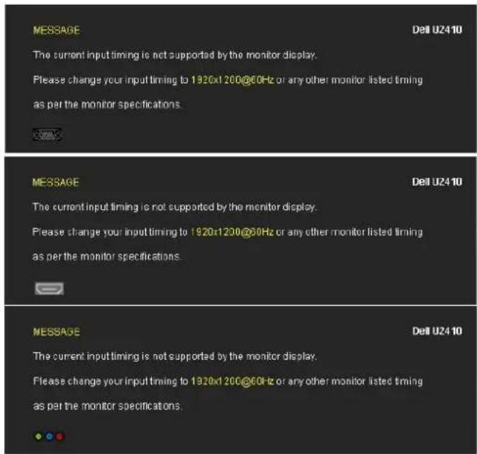
When the monitor does not support a particular resolution mode you will see the following message :
text_image
MESSAGE The current input timing is not supported by the monitor display. Please change your input timing to 1920x1 200@60Hz or any other monitor listed timing as per the monitor specifications. MESSAGE The current input timing is not supported by the monitor display. Please change your input timing to 1920x1 200@60Hz or any other monitor listed timing as per the monitor specifications. MESSAGE The current input timing is not supported by the monitor display. Please change your input timing to 1920x1 200@60Hz or any other monitor listed timing as per the monitor specifications.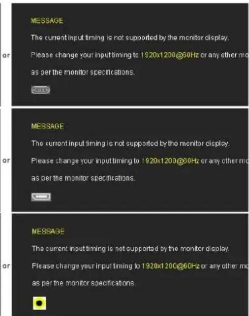
text_image
MESSAGE The current input timing is not supported by the monitor display. Please change your input timing to 1920x1200@60Hz or any other mode as per the monitor specifications. MESSAGE The current input timing is not supported by the monitor display. Please change your input timing to 1920x1200@60Hz or any other mode as per the monitor specifications. MESSAGE The current input timing is not supported by the monitor display. Please change your input timing to 1920x1200@60Hz or any other mode as per the monitor specifications.This means that the monitor cannot synchronize with the signal that it is receiving from the computer. See Monitor Specifications for the Horizontal and Vertical f addressable by this monitor. Recommended mode is 1920 X 1200.
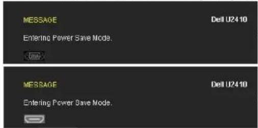
When monitor enters Power Save mode, the following message appears :
text_image
MESSAGE Dell U2410 Entering Power Save Mode. MESSAGE Dell U2410 Entering Power Save Mode.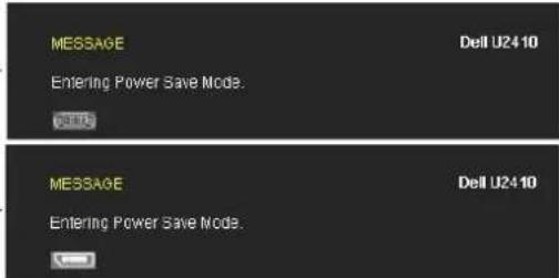
text_image
MESSAGE Dell U24 10 Entering Power Save Mode. MESSAGE Dell U24 10 Entering Power Save Mode.Activate the computer and wake up the monitor to gain access to the OSD.
If you Touch any button other than the power button one of the following messages will appear depending on the selected input:
VGA/DVI-D/HDMI/DisplayPort input
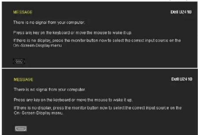
text_image
MESSAGE There is no signal from your computer. Press any key on the keyboard or move the mouse to wake it up. If there is no display, press the monitor button now to select the correct input source on the On-Screen-Display menu. MESSAGE There is no signal from your computer. Press any key on the keyboard or move the mouse to wake it up. If there is no display, press the monitor button now to select the correct input source on the On-Screen-Display menu.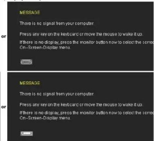
text_image
MESSAGE There is no signal from your computer. Press any key on the keyboard or move the mouse to wake it up. If there is no display, press the monitor button now to select the corrected On-Screen-Display menu. MESSAGE There is no signal from your computer. Press any key on the keyboard or move the mouse to wake it up. If there is no display, press the monitor button now to select the corrected On-Screen-Display menu.Video Input
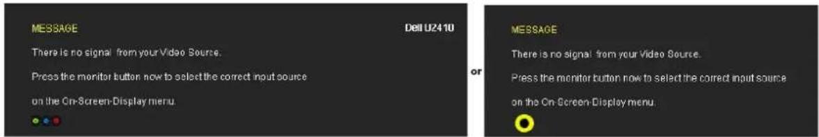
text_image
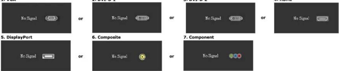
MESSAGE There is no signal from your Video Source. Press the monitor button now to select the correct input source on the On-Screen-Display menu. Dell U2410 MESSAGE There is no signal from your Video Source. Press the monitor button now to select the correct input source on the On-Screen Display menu.In PIP mode, when the monitor does not sense the selected second signal input, one of the following messages will appear depending upon the selected input as long as the OSD screen is closed.
- VGA
flowchart
graph TD
    A["No Signal"] --> B["or"]
    C["No Signal"] --> D["or"]
    E["No Signal"] --> F["or"]
    G["No Signal"] --> H["or"]
    I["No Signal"] --> J["or"]
    K["No Signal"] --> L["or"]
    M["No Signal"] --> N["or"]
    O["No Signal"] --> P["or"]
    Q["No Signal"] --> R["or"]
    S["No Signal"] --> T["or"]
    U["No Signal"] --> V["or"]
    W["No Signal"] --> X["or"]
    Y["No Signal"] --> Z["or"]
    AA["No Signal"] --> AB["or"]
    AC["No Signal"] --> AD["or"]
    AE["No Signal"] --> AF["or"]
    AG["No Signal"] --> AH["or"]
    AI["No Signal"] --> AJ["or"]
    AK["No Signal"] --> AL["or"]
    AM["No Signal"] --> AN["or"]
    AO["No Signal"] --> AP["or"]
    AQ["No Signal"] --> AR["or"]
    AS["No Signal"] --> AT["or"]
    AU["No Signal"] --> AV["or"]
    AW["No Signal"] --> AX["or"]
    AY["DisplayPort"] --> Z
    AZ["Composite"] --> AA
    BA["Component"] --> AB
If either VGA, DVI-D, HDMI or DisplayPort input is selected and all VGA, DVI-D, HDMI and DisplayPort cables are not connected, a floating dialog box as shown be
text_image
No VGA Cable Dell U2410 or No DVI-D1 Cable Dell U2410 or No DVI-D2 Cable No HDMI Cable Dell U2410 or No DisplayPort Cable Dell U2410
NOTE: When there is no valid input signal and the monitor is switch off and on, any active PIP/PBP window will disappear. Please enter PIP/PBP submenu t window.
See Solving Problems for more information.
Setting the Maximum Resolution
- Right-click on the desktop and select Properties.
- Select the Settings tab.
- Set the screen resolution to 1920 x 1200.
- Click OK.
If you do not see 1920 x 1200 as an option, you may need to update your graphics driver. Depending on your computer, complete one of the following procedures.
If you have a Dell desktop or portable computer:
- Go to support.dell.com, enter your service tag, and download the latest driver for your graphics card.
If you are using a non-Dell computer (portable or desktop):
- Go to the support site for your computer and download the latest graphic drivers.
- Go to your graphics card website and download the latest graphic drivers,
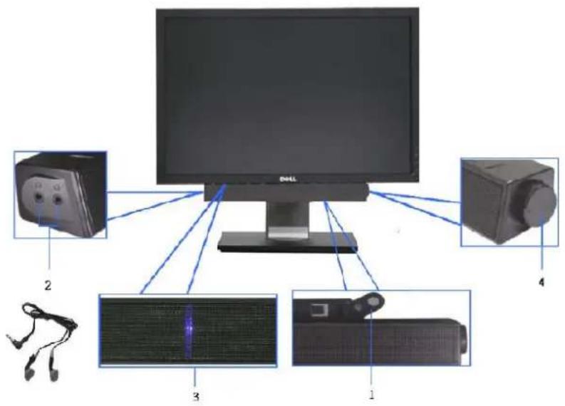
Using the Dell Soundbar (Optional)
The Dell Soundbar is a stereo two channel system adaptable to mount on Dell flat panel displays. The Soundbar has a rotary volume and on/off control to adjust the overall system level, a blue LED for power indication, and two audio headset jacks.
text_image
Diagram showing connections of a computer monitor to four labeled electronic devices, including a cable, speaker, and display.1 Attach Mechanism
2 Headphone Jacks
3 Power Indicator
4 Power/Volume Control
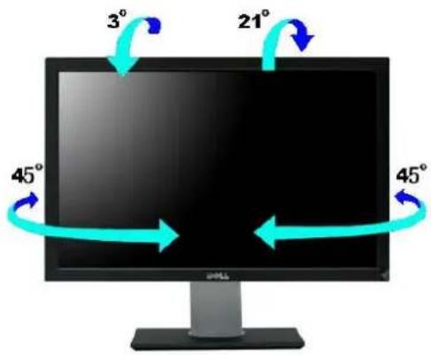
Using the Tilt, Swivel and Vertical Extension
Tilt/Swivel
With the built-in pedestal, you can tilt and/or swivel the monitor for the most comfortable viewing angle.
text_image
3° 21° 45° 45°
NOTE: Stand is NOT attached when the monitor is shipped from the factory.
Vertical Extension
Stand extends vertically up to 100 mm ± 5 mm.
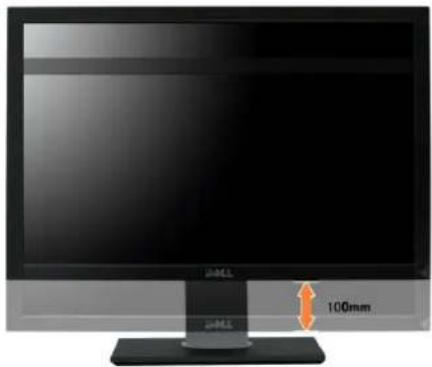
natural_image
Computer monitor with a 100mm height indicator and a black base (no text or symbols on the monitor itself)Rotating the Monitor
Before you rotate the monitor, your monitor should be fully vertically extended (Vertical Extension) and fully tilted (Tilt) up to avoid hitting the bottom edge of the monitor.
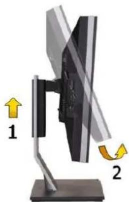
natural_image
Diagram of a computer monitor with two directional arrows indicating left and right motion (no text or symbols present)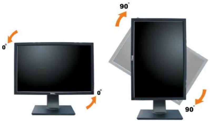
text_image
0° 90° 0° 90°NOTE: To use the Display Rotation function (Landscape versus Portrait view) with your Dell computer, you require an updated graphics driver that is not included with this monitor. To download the graphics driver, go to support.dell.com and see the Download section for Video Drivers for latest driver updates.
NOTE: When in Portrait View Mode, you may experience performance degradation in graphic-intensive applications (3D Gaming etc.).
When in Portrait View Mode, PIP/PBP is not available.
Adjusting the Rotation Display Settings of Your System
After you have rotated your monitor, you need to complete the procedure below to adjust the Rotation Display Settings of Your System.
NOTE: If you are using the monitor with a non-Dell computer, you need to go the graphics driver website or your computer manufacturer website for information on rotating the 'contents' on your display.
To adjust the Rotation Display Settings:
- Right-click on the desktop and click Properties.
- Select the Settings tab and click Advanced.
If you have an ATI graphics card, select the Rotation tab and set the preferred rotation.
If you have an nVidia graphics card, click the nVidia tab, in the left-hand column select NVRotate, and then select the preferred rotation.
If you have an Intel graphics card, select the Intel graphics tab, click Graphic Properties, select the Rotation tab, and then set the preferred rotation.
NOTE: If you do not see the rotation option or it is not working correctly, go to support.dell.com and download the latest driver for your graphics card.
Back to Contents Page
Setting Up Your Monitor
Dell™ U2410 Flat Panel Monitor
Important instructions to set the display resolution to 1920 x 1200 (Maximum)
For optimal display performance while using the Microsoft® Windows® operating systems, set the display resolution to 1920 x 1200 pixels by performing the following steps:
- Right-click on the desktop and click Properties.
- Select the Settings tab.
- Move the slider-bar to the right by pressing and holding left-mouse button and adjust the screen resolution to 1920 x 1200.
- Click OK.
If you do not see 1920 x 1200 as an option, you may need to update your graphics driver. Please choose the scenario below that best describes the computer system you are using, and follow the provided directions:
1: If you have a Dell™ desktop or a Dell™ portable computer with internet access.
2: If you have non Dell™ desktop, portable computer, or graphic card.
Dell™ U2410 Flat Panel Monitor
User's Guide
- Important instructions to set the display resolution to 1920 x 1200 (Maximum)
Information in this document is subject to change without notice.
© 2009-2011 Dell Inc. All rights reserved.
Reproduction of these materials in any manner whatsoever without the written permission of Dell Inc. is strictly forbidden.
Trademarks used in this text: Dell, the DELL logo, are trademarks of Dell Inc; Microsoft and Windows either registered trademarks or trademarks of Microsoft Corporation in the United States and/or other countries. Adobe is a trademark of Adobe Systems Incorporated, which may be registered in certain jurisdictions.
Other trademarks and trade names may be used in this document to refer to either the entities claiming the marks and names or their products. Dell Inc. disclaims any proprietary interest in trademarks and trade names other than its own.
Model U2410f
May 2011 Rev. A06
Back to Contents Page
Setting Up the Monitor
Dell™ U2410 Flat Panel Monitor User's Guide
- Attaching the Stand
Connecting the Monitor
Organizing Your Cables - Attaching the Soundbar (optional)
Attaching the Stand

NOTE: The stand is detached when the monitor is shipped from the factory.

natural_image
Hand holding a black electronic device with an orange arrow indicating rotation, mounted on a black base (no text or symbols visible)To attach the monitor stand:
- Remove the cover and place the monitor on it.
- Fit the two tabs on the upper part of the stand to the groove on the back of the monitor.
- Press the stand till it snaps into its place.
Connecting Your Monitor

WARNING: Before you begin any of the procedures in this section, follow the safety instructions.

NOTE: USB uplink cable connection enables USB ports and card reader on the monitor to work.
To connect your monitor to the computer perform the following steps/instructions:
- Turn off your computer and disconnect the power cable.
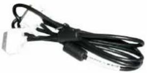
- Connect the USB uplink cable.
- Connect either the white (digital DVI-D) display connector cable, the blue (analog VGA) display connector cable, or the black DisplayPort cable to the corresponding video port on the back of your computer. Do not use all the cables on the same computer. Use all the cables only when they are connected to different computers with appropriate video systems.
Connecting the White DVI Cable and USB uplink cable
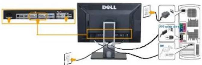
text_image
DELL USB cable BVI
NOTE: Your monitor supports two DVI ports. You can either choose DVI-D 1 or DVI-D 2 via input source on the OSD menu using Input source select.
Connecting the Blue VGA Cable and USB uplink cable
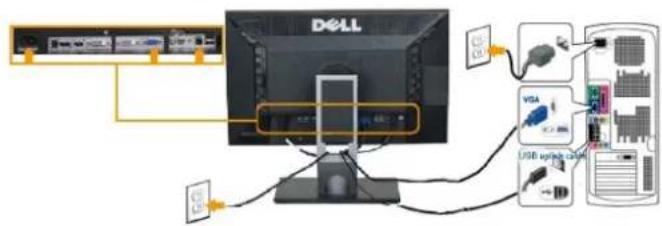
text_image
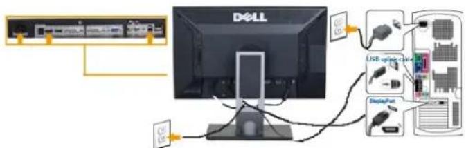
Diagram showing Dell computer connected to a USB drive via network cable, with labeled components including VGA and USB upgrade device.Connecting the Black DisplayPort Cable and USB uplink cable
text_image
DELL USB cable cable DisplayPortNOTE: The graphics are used for the purpose of illustration only. Appearance of the the computer may vary.
After you have completed connecting the DVI/VGA/DisplayPort cable, follow the procedure below to complete setting up your monitor:
- Plug the power cables for your computer and monitor into a nearby outlet.
- Turn on the monitor and the computer. Then change the input source via the OSD Menu Input Source Select from VGA or DVI input to DisplayPort input. If your monitor displays an image, installation is complete. If it does not display an image, see Solving Problems.
- Use the cable management slot on the monitor stand to organize the cables.
Organizing Your Cables
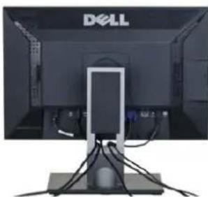
natural_image
Front view of a Dell monitor with cables and a central screen (no visible text or symbols)After attaching all necessary cables to your monitor and computer, (See Connecting Your Monitor for cable attachment,) use the cable management slot to neatly organize all cables as shown above.
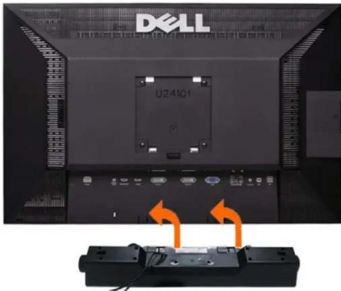
Attaching the Soundbar(Optional)
text_image
DELL U241Qf1 Working from the rear of the monitor, attach Soundbar by aligning the two slots with the two tabs along the bottom rear of the monitor.
2 Slide the Soundbar to the left until it snaps into place.
3 Connect the Soundbar with the DC power connector.
4 Insert the mini stereo plug from the rear of the Soundbar into the computer's audio output jack.

CAUTION: Do not use with any device other than Dell Soundbar

NOTE: Monitor DC power connector +12 V DC output is for Dell Soundbar, that does not have built-in AC adapter, eg Dell AX510.
Back to Contents Page
Back to Contents Page
Solving Problems
Dell™ U2410 Flat Panel Monitor User's Guide
Monitor Specific Troubleshooting
Built-in Diagnostics
Common Problems
Video Problems
Product Specific Problems
Universal Serial Bus (USB) Specific Problems
Troubleshooting the Dell™ Soundbar (Optional)
Card Reader Troubleshooting

WARNING: Before you begin any of the procedures in this section, follow the Safety Instructions.
Troubleshooting Your Monitor
Self-Test Feature Check (STFC)
Your monitor provides a self-test feature that allows you to check whether your monitor is functioning properly. If your monitor and computer are properly connected but the monitor screen remains dark, run the monitor self-test by performing the following steps:
- Turn off both your computer and the monitor.
- Unplug the video cable from the back of the computer. To ensure proper Self-Test operation, remove both Digital (white connector) and the Analog (blue connector) cables from the back of computer.
- Turn on the monitor.
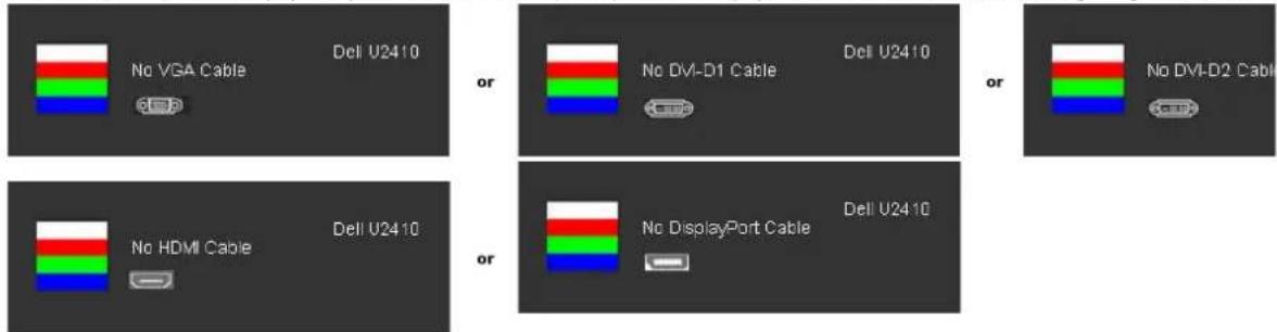
The floating dialog box should appear on-screen (against a black background) if the monitor cannot sense a video signal and is working correctly. While in self-test mode, the power LED remains blue. Also, depending upon the selected input, one of the dialogs shown below will continuously scroll through the screen.

text_image
No VGA Cable Del U2410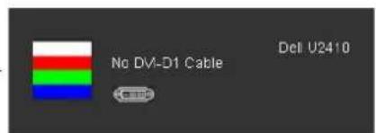
text_image
No DVI-D1 Cable Dell U2410
text_image
No DVI-D2 Cable Dell U2410
text_image
No HDMI Cable Dell U2410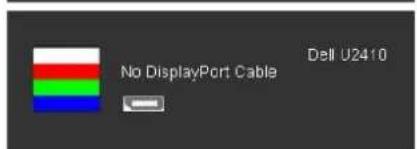
text_image
No DisplayPort Cable Dell U2410- This box also appears during normal system operation if the video cable becomes disconnected or damaged.
- Turn off your monitor and reconnect the video cable; then turn on both your computer and the monitor.
If your monitor screen remains blank after you use the previous procedure, check your video controller and computer system, because your monitor is functioning properly.

NOTE: Self-test feature check is not available for Composite, and Component video modes.
Built-in Diagnostics
Your monitor has a built-in diagnostic tool that helps you determine if the screen abnormality you are experiencing is an inherent problem with your monitor, or with your computer and video card.

NOTE: You can run the built-in diagnostics only when the video cable is unplugged and the monitor is in self-test mode.
To run the built-in diagnostics:
- Ensure that the screen is clean (no dust particles on the surface of the screen).
- Unplug the video cable(s) from the back of the computer or monitor. The monitor then goes into the self-test mode.
- Press and hold the first and fourth buttons on the front panel, simultaneously for 2 seconds. A gray screen appears.
text_image
Camera control panel with labeled buttons and indicators for display settings- Carefully inspect the screen for abnormalities.
- Press the fourth button on the front panel again. The color of the screen changes to red.
- Inspect the display for any abnormalities.
- Repeat steps 5 and 6 to inspect the display in green, blue, and white colored screens.
The test is complete when the white screen appears. To exit, press the fourth button again.
If you do not detect any screen abnormalities upon using the built-in diagnostic tool, the monitor is functioning properly. Check the video card and computer.
OSD Warning Messages
For OSD-related issues, see OSD Warning Messages.
Common Problems
The following table contains general information about common monitor problems you might encounter.
| Common Symptoms | What You Experience | Possible Solutions |
| No Video/Power LED off | No picture | Ensure that the video cable connecting the monitor and the computer is p and secure.Verify that the power outlet is functioning properly using any other electric Ensure that the power button is depressed fully. |
| No Video/Power LED on | No picture or no brightness | Increase brightness & contrast controls via OSD.Perform monitor self-test feature check.Check for bent or broken pins in the video cable connector.Touch button 5 located above the power button, ensure that the correct is selected via theInput Source Selectmenu.Run the built-in diagnostics. |
| Poor Focus | Picture is fuzzy, blurry, or ghosting | Perform Auto Adjust via OSD.Adjust the Phase and Pixel Clock controls via OSD.Eliminate video extension cables.Reset the monitor to Factory Settings.Change the video resolution to the correct aspect ratio (16:10). |
| Shaky/Jittery Video | Wavy picture or fine movement | Perform Auto Adjust via OSD.Adjust the Phase and Pixel Clock controls via OSD.Reset the monitor to Factory Settings.Check environmental factors.Relocate the monitor and test in another room. |
| Missing Pixels | LCD screen has spots | Cycle power on-off.Pixel that is permanently off is a natural defect that can occur in LCD techFor more information on Dell Monitor Quality and Pixel Policy, see Dell Support sitsupport.dell.com. |
| Stuck-on Pixels | LCD screen has bright spots | Cycle power on-off.Pixel that is permanently off is a natural defect that can occur in LCD techFor more information on Dell Monitor Quality and Pixel Policy, see Dell Support sitsupport.dell.com. |
| Brightness Problems | Picture too dim or too bright | Reset the monitor to Factory Settings.Auto Adjust via OSD.Adjust brightness & contrast controls via OSD. |
| Geometric Distortion | Screen not centered correctly | Reset the monitor to Factory Settings.Auto Adjust via OSD.Adjust brightness & contrast controls via OSD.NOTE: When using 'DVI-D', the positioning adjustments are not available. |
| Horizontal/Vertical Lines | Screen has one or more lines | Reset the monitor to Factory Settings.Perform Auto Adjust via OSD.Adjust Phase and Pixel Clock controls via OSD.Perform monitor self-test feature check and determine if these lines are all mode.Check for bent or broken pins in the video cable connector.NOTE: When using 'DVI-D', the Pixel Clock and Phase adjustments are not avail |
| Synchronization Problems | Screen is scrambled or appears torn | Reset the monitor to Factory Settings.Perform Auto Adjust via OSD.Adjust Phase and Pixel Clock controls via OSD.Perform monitor self-test feature check to determine if scrambled screen a test mode.Check for bent or broken pins in the video cable connector.Restart the computer in the safe mode. |
| Safety-Related Issues | Visible signs of smoke or sparks | Do not perform any troubleshooting steps.Contact Dell immediately. |
| Intermittent Problems | Monitor malfunctions on & off | Ensure that the video cable connecting the monitor to the computer is cor and is secure.Reset the monitor to Factory Settings.Perform monitor self-test feature check to determine if the intermittent pro self-test mode. |
| Missing Color | Picture missing color | Perform monitor self-test feature check.Ensure that the video cable connecting the monitor to the computer is cor and is secure.Check for bent or broken pins in the video cable connector. |
| Wrong Color | Picture color not good | Change the Color Setting Mode in the Color Settings OSD to Graphics or V to the application.Try different Color Preset Settings in Color Settings OSD. Adjust R/G/B val Settings OSD if the Color Management is turned off.Change the Input Color Format to PC RGB or YPbPr in the Advance Setting |
| Image retention from a static image left on the monitor for a long period of time | Faint shadow from the static image displayed appears on the screen | Use the Power Management feature to turn off the monitor at all times wh more information, seePower Management Modes).Alternatively, use a dynamically changing screensaver. |
Video Problems
| COMMON SYMPTOMS | WHAT YOU EXPERIENCE | POSSIBLE SOLUTIONS |
| No Video | No signal indicator is displayed | Check Video Input SelectionComposite: Yellow colored RCA jackComponent: Red, Blue, Green colored RCA jacks |
| Low Quality DVD playback | Picture not crisp and some color distortion | Check DVD connectionComposite gives good pictureComponent: Red, Blue, Green colored RCA jacks |
| Blinking Video | Video is blinking or discontinuous | Check DVD connectionComposite gives good pictureComponent: Red, Blue, Green colored RCA jacksCheck if DVD player is HDCP compliant.Some non-compliant players may exhibit blinking video and others v raster screen. |
Product Specific Problems
| SPECIFIC SYMPTOMS | WHAT YOU EXPERIENCE | POSSIBLE SOLUTIONS |
| Screen image is too small | Image is centered on screen, but does not fill entire viewing area | Perform monitor reset on "Factory Reset". |
| Cannot adjust the monitor with the buttons on the front panel | OSD does not appear on the screen | Turn the monitor off and unplug the power cord and then plug back and p |
| The monitor will not go into | No picture, the LED light is blue. When | Move mouse or hit any key on the keyboard on the computer or activate v |
| power saving mode. | press "+", "-" or "Menu" key, the message " No Composite input signal " or " No Component input signal " will appear. | access the OSD to set Audio to "off " state. |
| No Input Signal when you press the controls. | No picture, the LED light is blue. When you press "+" or "Menu" key, the message " No Composite input signal " or " No Component input signal " will appear. | Check the signal source Make sure the Computer is not in power saving by mouse or pressing any key on the keyboard.Check to make sure Video Source to Composite or Component is powered video media.Check whether the signal cable is plugged in and seated properly. Re-plant if necessary.Re-boot the computer or video player. |
| The monitor will not fill the entire screen. | The picture can't fill the height or width of the screen. | Due to the non-standard formats of DVDs, the monitor may not show the pictures. |

NOTE: When choosing DVI-D, DisplayPort, HDMI, Composite or Component video, Auto Adjust function is not available.
Universal Serial Bus (USB) Specific Problems
| SPECIFIC SYMPTOMS | WHAT YOU EXPERIENCE | POSSIBLE SOLUTIONS |
| USB interface is not working | USB peripherals are not working | Check that your monitor is powered ON.Reconnect the upstream cable to your computer.Reconnect the USB peripherals (downstream connector).Switch off and then turn on the monitor again.Reboot the computer. |
| High Speed USB 2.0 interface is slow. | High Speed USB 2.0 peripherals working slowly or not at all. | Check that your computer is USB 2.0 capable.Verify USB 2.0 source on your computer.Reconnect the upstream cable to your computer.Reconnect the USB peripherals (downstream connector).Reboot the computer. |
Troubleshooting the Dell™ Soundbar
| COMMON SYMPTOMS | WHAT YOU EXPERIENCE | POSSIBLE SOLUTIONS |
| No Sound | No power to Soundbar - the power indicator is off.(built-in DC power supply, i.e. U2410) | Turn the Power/Volume knob on the Soundbar clockwise to the middle post power indicator (blue LED) on the front of the Soundbar is illuminated.Confirm that the power cable from the Soundbar is plugged into the monit Confirm that the monitor has power.If the monitor has no power, seeMonitor Specific Troubleshootingfor more problem. |
| No Sound | Soundbar has power - power indicator is on. | Plug the audio line-in cable into the computer's audio out jack.Set all Windows volume controls to their maximum.Play some audio content on the computer (i.e. audio CD, or MP3).Turn the Power/Volume knob on the Soundbar clockwise to a higher volumClean and reseat the audio line-in plug.Test the Soundbar using another audio source (i.e. portable CD player). |
| Distorted Sound | Computer's sound card is used as the audio source. | Clear any obstructions between the Soundbar and the user.Confirm that the audio line-in plug is completely inserted into the jack of tSet all Windows volume controls to their midpoints.Decrease the volume of the audio application.Turn the Power/Volume knob on the Soundbar counter-clockwise to a lowClean and reseat the audio line-in plug.Troubleshoot the computer's sound card.Test the Soundbar using another audio source (i.e. portable CD player). |
| Distorted Sound | Other audio source is used. | Clear any obstructions between the Soundbar and the user.Confirm that the audio line-in plug is completely inserted into the jack of tDecrease the volume of the audio source.Turn the Power/Volume knob on the Soundbar counter-clockwise to a lowClean and reseat the audio line-in plug. |
| Unbalanced Sound Output | Sound from only one side of Soundbar | Clear any obstructions between the Soundbar and the user.Confirm that the audio line-in plug is completely inserted into the jack of taudio source.Set all Windows audio balance controls (L-R) to their midpoints.Clean and reseat the audio line-in plug.Troubleshoot the computer's sound card.Test the Soundbar using another audio source (i.e. portable CD player). |
| Low Volume | Volume is too low. | Clear any obstructions between the Soundbar and the user.Turn the Power/Volume knob on the Soundbar clockwise to the maximumSet all Windows volume controls to their maximum.Increase the volume of the audio application.Test the Soundbar using another audio source (i.e. portable CD player). |
Troubleshooting the Card Reader

CAUTION: Do not remove the device while reading or writing media. Doing so may cause loss of data or malfunction in the media.
| Problem | Cause | Solution |
| Drive letter is not assigned. (Windows® XP only) | Conflict with network drive letter. | A. Right-click My Computer on the desktop, and then click Manage. Under Compc click Desk Management.B. In the list of drives in the right panel, right-click Removable Device and then c Letter and Paths.C. Click Change, and in the drop-down box, specify a drive letter for the Remova choosing one that is not assigned to the mapped network drives.D. Click OK, ... then click OK again |
| Drive letter is assigned, but the media is not accessible | The media needs reformatting. | Right-click the drive in Explorer and choose Format from the resulting menu. |
| The media has been ejected during writing or erasing. | Displays the error message, "Error copying file or folder."Displays the error message, "Cannot write folder (folder name) or file (file name)," during writing, or, "Cannot remove folder (folder name) or file(file name),". While erasing, you cannot write or erase in the same folder or file name. | Reinsert the media and write or erase again.Format the media for writing or erasing the same folder or file name. |
| Despite the disappearance of the pop-up window, the media has been ejected while the LED was blinking. | Although the pop-up window disappears during writing, if you eject your media while the LED is still blinking, then you cannot complete your action on the media. | Format the media for writing or erasing the same folder or file name. |
| Cannot format or write on the media. | Write protect switch is enabled. | Verify that the write- protect switch of the media is unlocked. |
| Card reader is not working | USB interface is not working. | Check that your monitor is powered on.Reconnect the upstream cable from your computer to the monitor.Reinsert the media.Switch off and then turn on the monitor again.Reboot the computer. |
Back to Contents Page