TME-M770 - Car stereo ALPINE - Free user manual and instructions
Find the device manual for free TME-M770 ALPINE in PDF.
| Product Type | Video Monitor with DVD Player |
| Brand | ALPINE |
| Model | TME-M770 |
| Dimensions (mm) | 178 x 50 x 160 (height x width x depth) |
| Weight (kg) | 2.5 |
| Power Supply | 14.4 V DC (10 A) |
| Main Functions | DVD/CD/MP3/WMA playback, AM/FM tuner, 7" touch screen, motorized tilt |
| Maintenance and Cleaning | Wipe with a soft, dry cloth |
| Safety | Disconnect battery before installation, do not block vents |
| Spare Parts and Repairability | Parts available from Alpine customer service, repair by qualified technician |
| General Information | Multimedia car stereo with retractable screen |
Frequently Asked Questions - TME-M770 ALPINE
User questions about TME-M770 ALPINE
0 question about this device. Answer the ones you know or ask your own.
Ask a new question about this device
Download the instructions for your Car stereo in PDF format for free! Find your manual TME-M770 - ALPINE and take your electronic device back in hand. On this page are published all the documents necessary for the use of your device. TME-M770 by ALPINE.
USER MANUAL TME-M770 ALPINE
7300 Warden Ave., Suite 203, Markham,
Ontario L3R 9Z6, Canada
Phone 1-800-ALPINE-1 (1-800-257-4631)
ALPINE ELECTRONICS OF AUSTRALIA PTY. LTD.
6-8 Fifeways Boulevarde Keysborough,
Victoria 3173, Australia
Phone 03-9769-0000
ALPINE ELECTRONICS GmbH
Frankfurter Ring 117, 80807 München,
Germany
Phone 089-32 42 640
ALPINE ELECTRONICS OF U.K., LTD.
Fletchamstead Highway,
Coventry CV4 9TW. U.K.
Phone 0870-33 33 763
ALPINE ELECTRONICS FRANCE S.A.R.L.
(RCS PONTOISE B 338 101 280)
98, Rue de la Belle Etoile, Z.I. Paris
Nord II, B.P. 50016, 95945, Roissy
Charles de Gaulle Cedex, France
Phone 01-48 63 89 89
Operating Instructions

WARNING
WARNING 2
CAUTION 3
PRECAUTIONS ...... 3

Basic Operation
Screen Display ON/OFF 4
Adjusting the Volume 4
Switching the Source 4
Other Useful Features
Setup Operation 5
VISUAL EQ ^TM Operation 7
Changing to Another Product's Source ....8
Operating Other Products 8
Information
In Case of Difficulty 10
Specifications 10
Installation and Connections
Warning 11
Caution 11
Precautions 12
Installation 13
Connections 16

WARNING
This symbol means important instructions. Failure to heed them can result in serious injury or death.
DO NOT OPERATE ANY FUNCTION THAT TAKES YOUR ATTENTION AWAY FROM SAFELY DRIVING YOUR VEHICLE.
Any function that requires your prolonged attention should only be performed after coming to a complete stop. Always stop the vehicle in a safe location before performing these functions. Failure to do so may result in an accident.
KEEP THE VOLUME AT A LEVEL WHERE YOU CAN STILL HEAR OUTSIDE NOISE WHILE DRIVING.
Failure to do so may result in an accident.
MINIMIZE DISPLAY VIEWING WHILE DRIVING.
Viewing the display may distract the driver from looking ahead of the vehicle and cause an accident.
DO NOT DISASSEMBLE OR ALTER.
Doing so may result in an accident, fire or electric shock.
USE THIS PRODUCT FOR MOBILE 12V APPLICATIONS.
Use for other than its designed application may result in fire, electric shock or other injury.
KEEP SMALL OBJECTS SUCH AS BATTERY OUT OF THE REACH OF CHILDREN.
Swallowing them may result in serious injury. If swallowed, consult a physician immediately.
USE THE CORRECT AMPERE RATING WHEN REPLACING FUSES.
Failure to do so may result in fire or electric shock.
DO NOT WATCH VIDEO WHILE DRIVING.
Watching the video may distract the driver from looking ahead of the vehicle and cause an accident.
INSTALL THE PRODUCT CORRECTLY SO THAT THE DRIVER CANNOT WATCH TV/VIDEO UNLESS THE VEHICLE IS STOPPED AND THE EMERGENCY BRAKE IS APPLIED.
It is dangerous for the driver to watch TV/Video while driving a vehicle. Installing this product incorrectly enables the driver to watch TV/Video while driving. This may cause a distraction, preventing the driver from looking ahead, thus causing an accident. The driver or other people could be severely injured.

CAUTION
This symbol means important instructions. Failure to heed them can result in injury or material property damage.
HALT USE IMMEDIATELY IF A PROBLEM APPEARS.
Failure to do so may cause personal injury or damage to the product. Return it to your authorized Alpine dealer or the nearest Alpine Service Centre for repairing.

PRECAUTIONS
Temperature
Be sure the temperature inside the vehicle is between +45^ ( +113^ ) and 0^ ( +32^ ) before turning your unit on.
Fuse Replacement
When replacing the fuse(s), the replacement must be of the same amperage as shown on the fuse holder. If the fuse(s) blows more than once, carefully check all electrical connections for shorted circuitry. Also have your vehicle's voltage regulator checked.
Maintenance
If you have problems, do not attempt to repair the unit yourself. Return it to your Alpine dealer or the nearest Alpine Service Station for servicing.
Installation Location
Make sure the TME-M770 will not be exposed to:
- Direct sun and heat
- High humidity
- Excessive dust
• Excessive vibrations - After turning the system off, a slight ghost of the image will remain temporarily. This is an effect peculiar to LCD technology and is normal.
- Under cold temperature conditions, the screen may lose contrast temporarily. After a short warm-up period, it will return to normal.
About the Touch Switch
- To protect the display, lightly touch the screen with the tip of your finger.
- If there is no response from the switch, then move your finger away from the screen and touch again.
Basic Operation
text_image
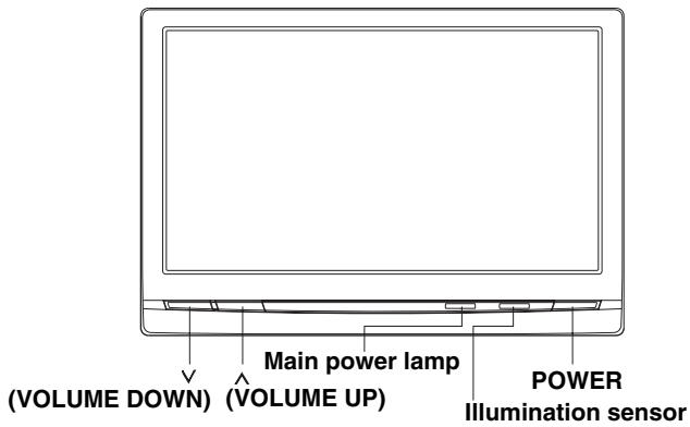
(VOLUME DOWN) (VOLUME UP) Main power lamp POWER Illumination sensorScreen Display ON/OFF
1 Press the POWER button.
2 To turn off the POWER, press the POWER button again.
- If properly connected, the monitors main POWER will turn off when the vehicle's ignition switch is off. If the main power lamp illuminates in the STAND BY mode, the vehicle's battery may be discharged.
- After turning the system off, a slight ghost of the image will remain temporarily. This is an effect peculiar to LCD technology and is normal.
- Under cold temperature conditions, the screen may lose contrast temporarily. After a short warm-up period, it will return to normal.
Adjusting the Volume
1 Adjust the volume level by pressing the ∨ or ∧ button.
Switching the Source
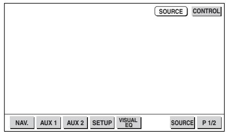
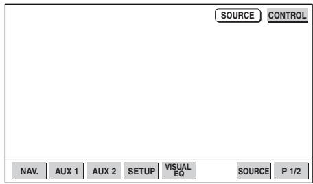
1 Touch the option part of the display to display each source operation screen or source selection screen.
2 If each source operation screen is displayed, touch CONTROL on the upper right side of the screen to display the source selection screen.
- The source selection screen is displayed by touching “CONTROL” as described below, depending on the current source.
When touched while the current source is GAME, AUX 1 or AUX 2 : Source selection screen When touched while the current source is EXT.DVD: EXT.DVD operation screen → Source selection screen When touched while the current source is TV: TV operation screen → Source selection screen When touched while the current source is LINK: AUDIO operation screen → EXT.DVD operation screen → TV operation screen → Source selection screen
3 Touch the source (NAV. / AUX 1/ AUX 2) you want to view.
text_image
SOURCE CONTROL NAV. AUX 1 AUX 2 SETUP VISUAL EQ SOURCE P 1/2- The AUX 1, AUX 2 source name changes to the selected mode name in the next item “SETUP operation” - “⑥External input name setting”. Also, “NAV.” is only displayed when “⑦Navigation Settings” in following section, “Setup Operation”, is set to “ON”.
- The operation screens for the different sources as well as the source selection screen turn off automatically if no operation is performed for 5 seconds.
Other Useful Features
Setup Operation
1 Touch the option part of the display to display each source operation screen or source selection screen.
2 If each source operation screen is displayed, touch CONTROL on the upper right side of the screen to display the source selection screen.
3 Touch SETUP.
4 Select the desired setting item screen by touching ▲ or ▼.
5 Change the setting by touching ◀ or ▶.
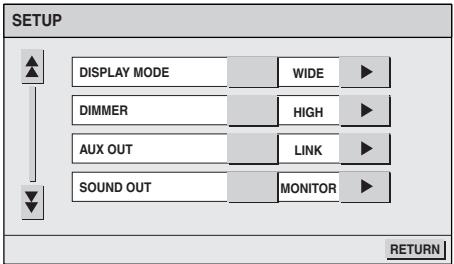
text_image
SETUP DISPLAY MODE WIDE DIMMER HIGH AUX OUT LINK SOUND OUT MONITOR RETURN① Display mode selection for the display (DISPLAY MODE)
WIDE
Normal images are expanded uniformly in the horizontal direction and are displayed over the entire screen.

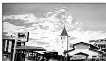
ZOOM
Normal images are expanded in the horizontal direction and are displayed over the entire screen. The expansion ratio increases towards the right and left edges of the screen.

natural_image
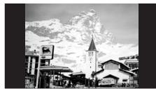
Black-and-white photo of a church with a horse and snow-capped mountains in the background (no visible text or symbols)CINEMA
Normal images are expanded in the horizontal and vertical directions. The top and bottom of the image are cut off. This mode is suited for 16:9 cinema size images.
NORMAL
Normal image (4:3)
② Dimmer adjustment (DIMMER)
HIGH : The backlighting is set to the value adjusted at “DIMMER HIGH LEVEL”.
LOW : The backlighting is set to the value adjusted at "DIMMER LOW LEVEL".
AUTO: Display illumination can be adjusted automatically depending on the brightness in the car. (Within the range of DIMMER HIGH LEVEL and DIMMER LOW LEVEL)
Continued
Other Useful Features
③ Rear monitor select function (AUX OUT)
LINK : Output the video/audio portion shown on the main monitor, to the rear monitor.
AUX1 : Output the AUX1 video/audio to the rear monitor.
AUX2 : Output the AUX2 video/audio to the rear monitor.
④ Change sound output (SOUND OUT)
MONITOR : Outputs sound through the built-in speakers.
HEADPHONE : Outputs sound to headphones if connected.
* Note that sound will not be output unless the audio output settings are appropriate.
⑤ External input sound level adjustment (AUX IN 1 LEVEL/AUX IN 2 LEVEL)
HIGH: Sets the sound level at a high level. LOW : Reduces the sound level.
⑥ External input name setting (AUX IN 1 MODE/AUX IN 2 MODE)
Select the name from the following list, to be used for the product using the external input mode. This will apply to the touch switch name at source selection time and the source name during playback change.
OFF/TV/EXT.DVD/GAME/AUX 1 (2)/LINK (AUX 1 MODE only)
- Set to “LINK” when the IVA-D300 series or VPE-S431 is connected. (Be sure to connect to the “AUX IN 1” connector.)
- Set to “EXT.DVD” when the DVA-5210, DVA-5205 series, DHA-S680 series or the like is connected.
- Set to "TV" if a TV tuner is connected to this product.
- The way the source operation screens and the source selection screen switches when “CONTROL” is touched differs according to the selected mode. (See page 4 “Switching the Source”, step 2.)
⑦ Navigation settings (NAV. IN)
When the navigation is connected, set to ON.
⑧ Dimmer HIGH level adjustment (DIMMER HIGH LEVEL)
Adjusts the HIGH LEVEL (16 (MIN) to 31 (MAX)) of the dimmer.
⑨ Dimmer LOW level adjustment (DIMMER LOW LEVEL)
Adjusts the LOW LEVEL (0 (MIN) to 15 (MAX)) of the dimmer.
⑩ Touch panel adjustment (SCREEN ALIGNMENT)
Adjust if the LCD display position and touch panel position do not match.
▶ : Reset to default settings.
▶: Changes to adjustment screen. The adjustment method is as follows.
1) Touch ▶ from SCREEN ALIGNMENT. The screen changes to the adjustment screen.
2) Touch the ⚗ mark on the lower left side of the screen. The adjustment screen switches.
3) Touch the X mark on the upper right side of the screen. When the adjustment is finished, the screen returns to the SETUP screen.
- If you touch RETURN on the adjustment screen, nothing is adjusted and the screen returns to the SETUP screen.
6 When the settings are completed, touch RETURN.
The screen returns to the source selection screen.
1 Touch the option part of the display to display each source operation screen or source selection screen.
2 If each source operation screen is displayed, touch CONTROL on the upper right side of the screen to display the source selection screen.
3 Touch VISUAL EQ.
4 Select the desired setting by touching ▲ or ▼.
5 Change the selected setting by touching ◀ or ▶.
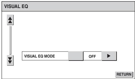
text_image
VISUAL EQ VISUAL EQ MODE OFF RETURN① VISUAL EQ mode (manufacturer's settings) selection (VISUAL EQ MODE)
OFF : Default setting.
NIGHT M. : Suitable for movies with a lot of dark scenes.
SOFT : Suitable for movies with computer graphics or animation.
SHARP : Suitable for old movies whose resolution is unclear.
CONTRAST: Suitable for the latest movies.
P.SET-1, 2 : Accesses the preset number stored in step “⑦ Storing”.
- To return to the default values after selecting one of the modes between “NIGHT M.” and “CONTRAST” then adjusting the image brightness, color density and so on to suit your tastes, set this function to “OFF”.
② Brightness adjustment (BRIGHT)
Allows the brightness (-15 (MIN)\~+15 (MAX)) of the picture.
③ Color depth adjustment (COLOR)
Change depth can be adjusted from -15 (MIN) to +15 (MAX).
* Adjustment cannot be made in the NAVIGATION (RGB connection) mode.
④ Tint tone adjustment (TINT)
Tint tone can be adjusted from G15 (G MAX) to R15 (R MAX).
* Adjustment cannot be made in the NAVIGATION (RGB connection) mode.
⑤ Contrast adjustment (CONTRAST)
Contrast can be adjusted from -15 (LOW) to +15 (HIGH).
⑥ Screen quality adjustment (SHARP)
Screen quality can be adjusted from -15 (SOFT) to +15 (HARD).
⑦ Storing (USER MEMORY)
You can store the settings adjusted in steps ② to ⑥ in the following way.
1) Touch ◀ or ▶ from USER MEMORY after adjusting settings ② to ⑥, and select the preset number you want to store in (P.SET-1, 2).
2) After selecting the preset No., touch "WRITE".
- P.SET-1, 2 stored here can be accessed from “① VISUAL EQ mode selection”.
- If ② to ⑥ are adjusted, VISUAL EQ mode in ① changes to “CUSTOM”.
6 When setting is completed, touch RETURN. The screen changes to the source selection screen.
Other Useful Features
Changing to Another Product's Source
When used with touch panel compatible products such as the IVA-D300 series/VPE-S431, sources connected to those products are also selectable.
1 Touch the option part of the display to display each source operation screen or source selection screen.
2 If each source operation screen is displayed, touch CONTROL on the upper right side of the screen to display the source selection screen.
3 Touch SOURCE.
text_image
SOURCE CONTROL NAV. AUX 1 AUX 2 SETUP VISUAL EQ SOURCE P 1/2Each time you touch "SOURCE", the source changes.
The source depends on the settings and connections of the product used together with the IVA-D300 series.
Refer to the combined products instructions manuals.
After touching “SOURCE”, change the source with the following operation.
1) Touch "P 1/2".
The screen changes to "P 2/2".
2) Touch “◀” “▶” “▲” “▼” to select the desired source. Touch “ENTER”.
Touch "RETURN" to return to the previous screen.
- When “SETUP” is selected, the setup operation on the VPE-S431 can be performed in the same way as the source selection operation. For details on the setup items, see the VPE-S431’s operating instructions.
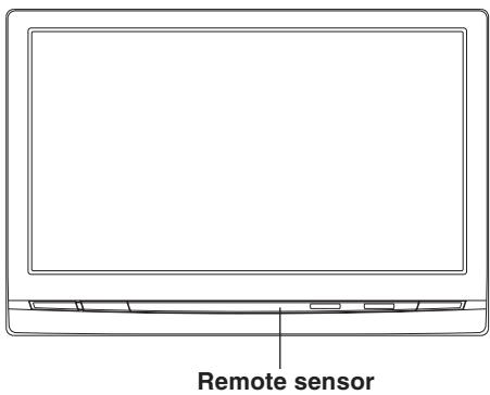
Remote Control Sensor
text_image
Remote sensor- Receives the remote control signal from connected ALPINE products such as navigation and DVD players.
Operating Other Products
When the TME-M770 is used in combination with a product designed to be operated from the TME-M770 (IVA-D300 series, DVA-5210, DHA-S680 series, etc.), some of the operations on the other product can be performed from the TME-M770. Below are some examples of the operations that can be performed.
Operating a DVD in the IVA-D300 series
1 Touch any point on the display. The “AUDIO” operation screen appears.
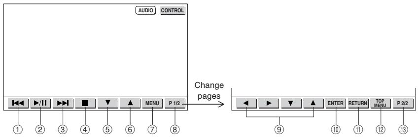
flowchart
graph LR
    A["Audio CONTROL"] --> B["1"]
    A --> C["2"]
    A --> D["3"]
    A --> E["4"]
    A --> F["5"]
    A --> G["6"]
    A --> H["7"]
    A --> I["8"]
    J["Change pages"] --> K["9"]
    K --> L["10"]
    K --> M["11"]
    K --> N["12"]
    K --> O["13"]
| Operation of DVD in IVA-D300 series | ||
| Touch | Long touch | |
| 1 | Play from start of current chapter | 2x fast reverse/8x fast reverse after 5 seconds |
| 2 | Play/pause | - |
| 3 | Play next chapter | 2x fast forward/8x fast forward after 5 secondsSlow play (from pause mode) |
| 4 | PRE STOP/STOP | STOP |
| 5 | - | - |
| 6 | - | - |
| 7 | Call out DVD menu | - |
| 8 | Switch page (function guide) | - |
| 9 | Move menu cursor | - |
| 10 | Enter (DVD menu) | - |
| 11 | - | - |
| 12 | - | Call out DVD top menu |
| 13 | Switch page (function guide) | - |
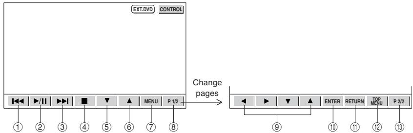
Operating the DVA-5210 and the DHA-S680 series
1 Touch the option part of the display.
The screen changes to the operation screen for each source.
2 Touch "CONTROL" on the upper right side of the screen. Display the "EXT.DVD" operation screen.
flowchart
graph LR
    A["EXT.DVD CONTROL"] --> B["Change pages"]
    B --> C["ENTER RETURN TOP MENU P 2/2"]
    style A fill:#f9f,stroke:#333
    style B fill:#ccf,stroke:#333
| Operation of a DVD player (DVA-5210) | Operation of a DVD changer (DHA-S680 series) | |||
| Touch | Long touch | Touch | Long touch | |
| 1 | Play from start of current chapter | 2x fast reverse/8x fast reverse after 5 seconds | Play from start of current chapter | 16x fast reverse |
| 2 | Play/pause | - | Play | Slow play |
| 3 | Play next chapter | 2x fast forward/8x fast forward after 5 secondsSlow play (from pause mode) | Play next chapter | 16x fast forward |
| 4 | PRE STOP/STOP | STOP | PRE STOP/STOP | - |
| 5 | - | - | Switch DISC | - |
| 6 | - | - | Switch DISC | - |
| 7 | Call out DVD menu | Call out DVD player setup screen* | Call out DVD menu | Call out DVD changer setup screen* |
| 8 | Switch page (function guide) | - | Switch page (function guide) | - |
| 9 | Move menu cursor | - | Move menu cursor | - |
| 10 | Enter (DVD menu) | - | Enter (DVD menu) | - |
| 11 | Move back 1 screen(DVD player setup)* | - | Move back 1 screen(DVD changer setup)* | - |
| 12 | Cue to start of chapter, track or elapsed time | Call out DVD top menu | Cue to start of chapter, track or elapsed time | Call out DVD top menu |
| 13 | Switch page (function guide) | - | Switch page (function guide) | - |
* Stop mode only
* Stop mode only
If a TV is operated (A TV tuner is connected)
1 Touch the option part of the display.
The screen changes to the operation screen for each source.
2 Touch "CONTROL" on the upper right side of the screen. Display the "TV" operation screen.
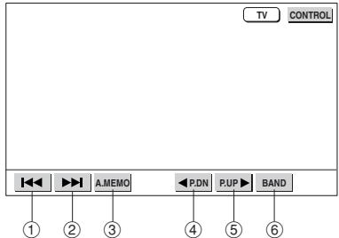
text_image
TV CONTROL A.MEMO P.DN P.UP BAND ① ② ③ ④ ⑤ ⑥| TV Operation | ||
| Touch | Long touch | |
| 1 | Channel down | - |
| 2 | Channel up | - |
| 3 | Auto memory | - |
| 4 | Preset channel down | - |
| 5 | Preset channel up | - |
| 6 | Change band | - |
Other Useful Features
- When connecting an IVA-D300 series to the TME-M770, be sure to connect it to the “AUX IN 1” connector and set the “AUX IN MODE” setting (SETUP) to “LINK”.
- When connecting a DVA-5210, DHA-S680 series, etc., to the TME-M770, set the “AUX IN MODE” setting (SETUP) to “EXT.DVD”.
- When connecting a TV tuner to the TME-M770, set the “AUX IN MODE” setting (SETUP) to “TV”.
- The TME-M770 and other components connected to it can be operated with a separately sold remote control unit. For instructions on operations using the remote control unit, see the remote control unit's operating instructions. When operating an IVA-D300 series, see the “Rear Entertainment Function” section of the IVA-D300 series's operating instructions.
- Depending on the connected component, some functions and operations may differ. Also refer to the operating instructions of the connected component.
Information
In Case of Difficulty
If you encounter a problem, please review the items in the following checklist. This guide will help you isolate the problem if the unit is at fault. Otherwise, make sure the rest of your system is properly connected or consult your authorized Alpine dealer.
No function or display.
- Car's ignition is off.
- Turn the ignition on.
- No fuse or blown fuse.
- Check the cause and replace the fuse.
- Incorrect connections.
- Check connection and remedy.
• Vehicle's battery is weak. - Check the voltage of vehicle's battery.
Unclear picture display.
- Fluorescent tube is exhausted.
- Replace the fluorescent tube*.
No picture display.
- Brightness control is set for minimum brightness control. - Adjust the brightness.
- Incorrect setting of the VTR mode.
Switch to the correct mode. - Protective circuit is on because of high temperature. - Wait until the temperature inside the vehicle comes down to the operating temperature range (45°C).
- Incorrect or open connection with the Monitor, AV interface unit.
- Check the connection and remedy.
Picture color is poor.
- Brightness/Color/Tint control are not set to the proper positions.
- Check each control.
Spots or dotted lines/stripes appear.
- Caused by neon signs, high-voltage power lines, CB transmitter, other vehicle's ignition plugs, etc.
- Change the location of your vehicle.
Unit does not operate.
• Monitor's power is not turned on.
- Turn on the monitor's power.
Navigation screen is not displayed or navigation system's remote controller keys do not work.
- Navigation system's power is turned off.
- Press the ON/OFF (POWER) button on the navigation system's remote controller to turn the navigation system's power on.
* The fluorescent tube replacement is not free of charge even within the warranty period, for the tube is an article of consumption.
Specifications
MONITOR
| Screen Size | 6.5-type |
| Display System | Low reflection rear projection type TN liquid crystal panel |
| Drive System | Active matrix drive, normally white display |
| Number of Picture Elements | 280,800 pcs. (H:1200 x V:234 dots) |
| Effective Number of Picture Elements | 99.99% or more |
| Light Source | Internal optical system (U-type cold cathode fluorescent tube) |
| Dimensions (W x H x D) | 161 x 109 x 28.5mm |
| Weight | 360g |
AV Interface Unit
| Dimensions (W x H x D) | 180 x 119 x 28.5 mm |
| Weight | 550g |
- Due to continuous product improvement, specifications and design are subject to change without notice.
- The LCD panel is manufactured using an extremely high precision manufacturing technology. Its effective pixel ratio is over 99.99%. This means that there is a possibility that 0.01% of the pixels could be either always ON or OFF.
Installation and Connections
Before installing or connecting the unit, please read the following and pages 2 and 3 of this manual thoroughly for proper use.

Warning
MAKE THE CORRECT CONNECTIONS.
Failure to make the proper connections may result in fire or product damage.
USE ONLY IN CARS WITH A 12 VOLT NEGATIVE GROUND.
(Check with your dealer if you are not sure.) Failure to do so may result in fire, etc.
BEFORE WIRING, DISCONNECT THE CABLE FROM THE NEGATIVE BATTERY TERMINAL.
Failure to do so may result in electric shock or injury due to electrical shorts.
DO NOT ALLOW CABLES TO BECOME ENTANGLED IN SURROUNDING OBJECTS.
Arrange wiring and cables in compliance with the manual to prevent obstructions when driving. Cables or wiring that obstruct or hang up on places such as the steering wheel, shift lever, brake pedals, etc. can be extremely hazardous.
DO NOT SPLICE INTO ELECTRICAL CABLES.
Never cut away cable insulation to supply power to other equipment. Doing so will exceed the current carrying capacity of the wire and result in fire or electric shock.
DO NOT USE BOLTS OR NUTS IN THE BRAKE OR STEERING SYSTEMS TO MAKE GROUND CONNECTIONS.
Bolts or nuts used for the brake or steering systems (or any other safety-related system), or tanks should NEVER be used for installations or ground connections. Using such parts could disable control of the vehicle and cause fire etc.
KEEP SMALL OBJECTS SUCH AS BATTERY OUT OF THE REACH OF CHILDREN.
Swallowing them may result in serious injury. If swallowed, consult a physician immediately.
DO NOT INSTALL IN LOCATIONS WHICH MIGHT HINDER VEHICLE OPERATION, SUCH AS THE STEERING WHEEL OR SHIFT LEVER.
Doing so may obstruct forward vision or hamper movement etc. and results in serious accident.
DO NOT DAMAGE PIPE OR WIRING WHEN DRILLING HOLES.
When drilling holes in the chassis for installation, take precautions so as not to contact, damage or obstruct pipes, fuel lines, tanks or electrical wiring. Failure to take such precautions may result in fire.
DO NOT INSTALL THE MONITOR NEAR THE PASSENGER SEAT AIR BAG.
If the unit is not installed correctly the air bag may not function correctly and when triggered the air bag may cause the monitor to spring upwards causing an accident and injuries.

Caution
HAVE THE WIRING AND INSTALLATION DONE BY EXPERTS.
The wiring and installation of this unit requires special technical skill and experience. To ensure safety, always contact the dealer where you purchased this product to have the work done.
USE SPECIFIED ACCESSORY PARTS AND INSTALL THEM SECURELY.
Be sure to use only the specified accessory parts. Use of other than designated parts may damage this unit internally or may not securely install the unit in place. This may cause parts to become loose resulting in hazards or product failure.
ARRANGE THE WIRING SO IT IS NOT CRIMPED OR PINCHED BY A SHARP METAL EDGE.
Route the cables and wiring away from moving parts (like the seat rails) or sharp or pointed edges. This will prevent crimping and damage to the wiring. If wiring passes through a hole in metal, use a rubber grommet to prevent the wire's insulation from being cut by the metal edge of the hole.
DO NOT INSTALL IN LOCATIONS WITH HIGH MOISTURE OR DUST.
Avoid installing the unit in locations with high incidence of moisture or dust. Moisture or dust that penetrates into this unit may result in product failure.
Installation and Connections
Precautions
- Be sure to disconnect the cable from the (−) battery post before installing your TME-M770. This will reduce any chance of damage to the unit in case of a short-circuit.
- Be sure to connect the color coded leads according to the diagram. Incorrect connections may cause the unit to malfunction or damage the vehicle's electrical system.
- When making connections to the car's electrical system, be aware of the factory installed components (e.g. on-board computer). Do not tap into these leads to provide power for this unit. When connecting the TME-M770 to the fuse box, make sure the fuse for the intended circuit of the TME-M770 has the appropriate amperage. Failure to do so may result in damage to the unit and/or the vehicle. When in doubt, consult your ALPINE dealer.
- The TME-M770 uses female RCA-type jacks for connection to other units having RCA connectors. You may need an adaptor to connect other units. If so, please contact your authorized ALPINE dealer for assistance.
IMPORTANT
Please record the serial number of your unit in the space provided below and keep it as a permanent record. The serial number plate is located on the rear of the monitor or on the bottom of the AV interface unit.
SERIAL NUMBER: ____ INSTALLATION DATE: ____ INSTALLATION TECHNICIAN: ____ PLACE OF PURCHASE: ____
Installing AV Interface Unit
This Unit can be placed inside the trunk, on the kick panel of the front passenger's seat or underdash. However, to avoid unnecessary signal wiring, it is better to mount the Unit as close as possible to the Display. DO NOT MOUNT THE INTERFACE UNIT IN LOCATIONS EXPOSED TO MOISTURE OR EXTREME HEAT (such as the engine compartment).
Velcro fastener Mounting:
- Place a Velcro fastener onto the mounting surface. The rough side should be facing the unit.
- Remove the backing to the adhesive on the Velcro strips. Press the unit onto the mounting location.
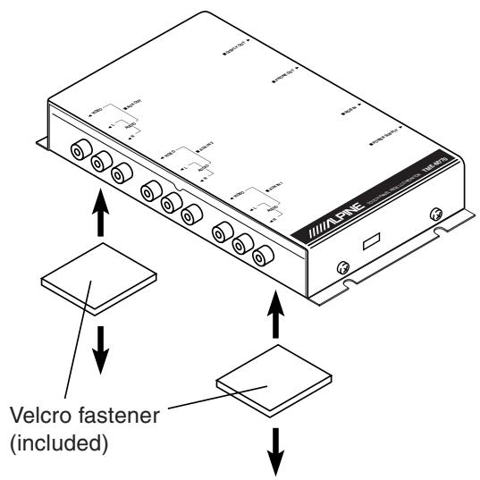
text_image
Velcro fastener (included)Attaching with screws
- Place the unit on the location chosen for installation.
- Mark the screw locations using the unit as a template.
- Drill a hole less than 3 mm in diameter.

WARNING
When you are drilling a hole in the car body, be careful not to damage pipes, tanks or electrical wiring etc.. It might cause an accident or a fire.
- Firmly attach the unit using 4 of the supplied self-tapping screws (M4 x 14).
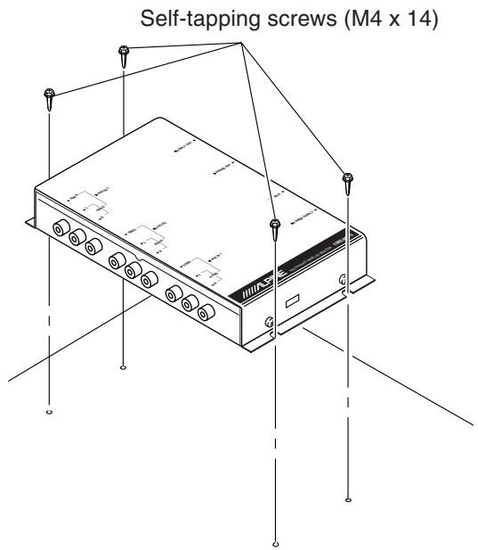
text_image
Self-tapping screws (M4 x 14)Installation and Connections
Attaching the monitor and stand

CAUTION
Do not install the monitor near the front passenger seat air bag system.
- When mounting with other than the attached Mounting Bracket, use the attached L shape bracket depending on usage.
1 Remove the main unit attachment fitting.
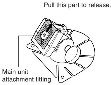
text_image
Pull this part to release. Main unit attachment fitting2 Loosen the main unit attachment fitting with a coin etc., slide it into the track on the rear of the main unit and temporarily fasten it. Then fix it to the stand.
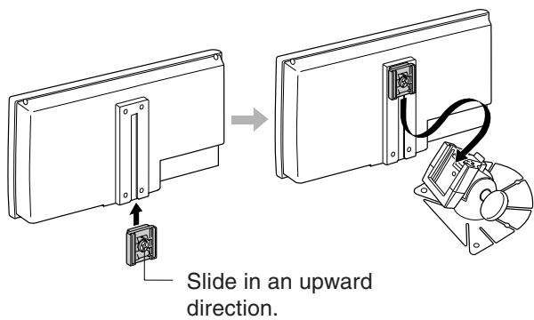
text_image
Slide in an upward direction.3 Check the sticking position.
① Temporarily fasten the stand with gum tape.
② Loosen the adjustment screws, and adjust to a safe, viewable position.
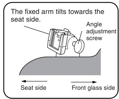
text_image
The fixed arm tilts towards the seat side. Angle adjustment screw Seat side Front glass side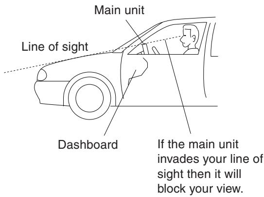
text_image
Main unit Line of sight Dashboard If the main unit invades your line of sight then it will block your view.In order to use safely, attach to the following places.
• Stable and secure places.
- Places that will not have your view blocked by the main unit when driving.
- Places that you will not hit against if you lean forward while you wearing your seatbelt.
- Places where the main unit cannot hit against the steering wheel while driving.
- Be aware that if the surface of the dashboard is leather, wooden panel, stretched fabric or any non-resin based product, then the surface will be damaged when you remove the stand.
- Do not place the main unit directly in front of the air conditioner vents.
4 Remove the main unit from the stand.
5 Remove the mount from the stand and stick it to the dashboard etc..
Remove any dirt on the place to install, using the supplied cloth.
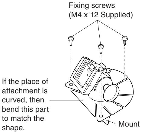
text_image
Fixing screws (M4 x 12 Supplied) If the place of attachment is curved, then bend this part to match the shape. Mount- If the temperature in the car is low (Winter), then first heat up the place where you are going to stick the mount with a hairdryer etc.
- Do not apply force to the mount, or expose to humidity, within 24 hours after attaching.
- If the mount is not firmly stuck, then we recommend that you attach with the supplied fixing screws.
6 Attach the main unit to the stand as shown in step 2.
Use the cable clamps to fix the cables.
- Before using, check that the main unit and the stand, and the stand and the place where it is attached to the car are fixed securely.
Installation and Connections
Connections
Make connections correctly.
Improper connections may cause a fire or operation failure.
Basic connection
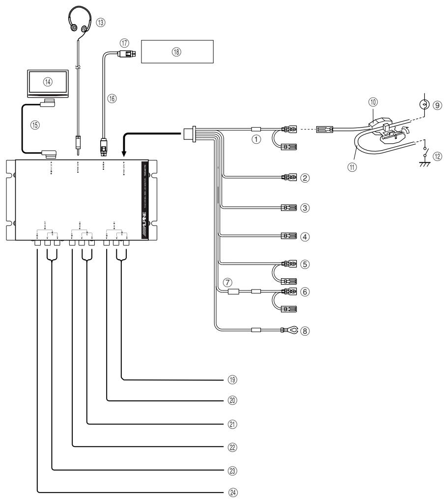
text_image
Technical diagram of an electronic device with numbered components and wiring connections① Parking brake lead (Yellow/Blue)
Connect this lead to the parking brake lead powered when parking brake is pulled.
② Monitor control lead (White/Pink)
Connect when upgrading with touch panel compatible products such as the IVA-D300 series.
③④Remote control output lead (White/Brown)
To remote control input lead of ALPINE products used in the system.
⑤ Reverse Lead (Orange/White)
Use only when a back-up camera is connected. Connect to the plus side of the car's reverse lamp that lights when the transmission is shifted into reverse (R).
Switches the video picture to the back-up camera. This is linked with putting the car into reverse (R).
⑥ ACC power lead (Red)
To ACC power lead powered when engine key position is ACC.
⑦ Fuse (7.5A)
⑧ Ground lead (Black)
Connect the lead to a good chassis ground on the vehicle. Make sure the connection is made to bare metal and is securely fastened using the sheet metal screw provided.
⑨ Brake Lamp
⑩ Brake Connector (Included)
⑪ Brake Signal Lead
⑫ Brake Switch
⑬ Headphone
⑭ Main monitor
⑮ Connection cable
⑯ RGB cable
⑰ To RGB output terminal
⑱ Made by Alpine navigation
⑲ Audio input connectors (AUX 1)
Use these connectors to input the audio signals from a DVD player, video deck etc.
⑳ Video input connector (AUX 1)
Use this connector to input the video signals from a DVD player, video deck etc.
②1 Audio input connectors (AUX 2)
Use these connectors to input the audio signals from a DVD player, video deck etc.
②2 Video input connectors (AUX 2)
Use this connector to input the video signals from a DVD player, video deck etc.
②3 Audio output connectors
Use these connectors to output audio signals to a rear monitor, etc.
⑳ Video output connector
Use this connector to output video signals to a rear monitor, etc.
- When connecting to an IVA-D300 series or VPE-S431, use the “AUX IN 1” connector. When connecting a rear view camera, use the “AUX IN 2”.
To prevent external noise from entering the audio system.
- Locate the unit and route the leads at least 10 cm away from the car harness.
- Keep the battery power leads as far away from other leads as possible.
- Connect the ground lead securely to a bare metal spot (remove the coating if necessary) of the car chassis.
- If you add an optional noise suppressor, connect it as far away from the unit as possible. Your Alpine dealer carries various Alpine noise suppressors, contact them for further information.
- Your Alpine dealer knows best about noise prevention measures so consult your dealer for further information.
System Connections
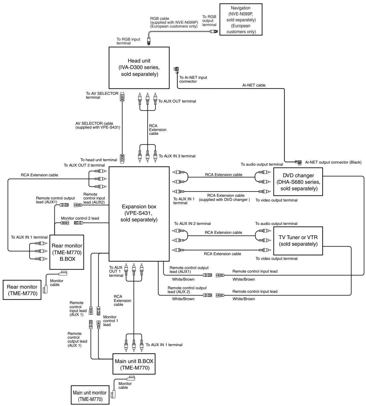
1) 2 main units + head unit (IVA-D300 series) + expansion box (VPE-S431) + navigation (NVE-N099P, European customers only) + DVD changer (DHA-S680 series) + TV Tuner
flowchart
graph TD
    A["Main unit monitor (TME-M770)"] --> B["Rear monitor (TME-M770)"]
    B --> C["Rear monitor (TME-M770) B.BOX"]
    C --> D["Expansion box (VPE-S431, sold separately)"]
    D --> E["Main unit B.BOX (TME-M770)"]
    E --> F["Main unit monitor (TME-M770)"]
    F --> G["Rear monitor (TME-M770) B.BOX"]
    G --> H["Rear monitor (TME-M770) B.BOX"]
    H --> I["Rear monitor (TME-M770) B.BOX"]
    I --> J["Rear monitor (TME-M770) B.BOX"]
    J --> K["Rear monitor (TME-M770) B.BOX"]
    K --> L["Rear monitor (TME-M770) B.BOX"]
    L --> M["Rear monitor (TME-M770) B.BOX"]
    M --> N["Rear monitor (TME-M770) B.BOX"]
    N --> O["Rear monitor (TME-M770) B.BOX"]
    O --> P["Rear monitor (TME-M770) B.BOX"]
    P --> Q["Rear monitor (TME-M770) B.BOX"]
    Q --> R["Rear monitor (TME-M770) B.BOX"]
    R --> S["Rear monitor (TME-M770) B.BOX"]
    S --> T["Rear monitor (TME-M770) B.BOX"]
    T --> U["Rear monitor (TME-M770) B.BOX"]
    U --> V["Rear monitor (TME-M770) B.BOX"]
    V --> W["Rear monitor (TME-M770) B.BOX"]
    W --> X["Rear monitor (TME-M770) B.BOX"]
    X --> Y["Rear monitor (TME-M770) B.BOX"]
    Y --> Z["Rear monitor (TME-M770) B.BOX"]
    Z --> AA["Rear monitor (TME-M770) B.BOX"]
    AA --> AB["Rear monitor (TME-M770) B.BOX"]
    AB --> AC["Rear monitor (TME-M770) B.BOX"]
    AC --> AD["Rear monitor (TME-M770) B.BOX"]
    AD --> AE["Rear monitor (TME-M770) B.BOX"]
    AE --> AF["Rear monitor (TME-M770) B.BOX"]
    AF --> AG["Rear monitor (TME-M770) B.BOX"]
    AG --> AH["Rear monitor (TME-M770) B.BOX"]
    AH --> AI["Rear monitor (TME-M770) B.BOX"]
    AI --> AJ["Rear monitor (TME-M770) B.BOX"]
    AJ --> AK["Rear monitor (TME-M770) B.BOX"]
    AK --> AL["Rear monitor (TME-M770) B.BOX"]
    AL --> AM["Rear monitor (TME-M770) B.BOX"]
    AM --> AN["Rear monitor (TME-M770) B.BOX"]
    AN --> AO["Rear monitor (TME-M770) B.BOX"]
    AO --> AP["Rear monitor (TME-M770) B.BOX"]
    AP --> AQ["Rear monitor (TME-M770) B.BOX"]
    AQ --> AR["Rear monitor (TME-M770) B.BOX"]
    AR --> AS["Rear monitor (TME-M770) B.BOX"]
    AS --> AT["Rear monitor (TME-M770) B.BOX"]
    AT --> AU["Rear monitor (TME-M770) B.BOX"]
    AU --> AV["Rear monitor (TME-M770) B.BOX"]
    AV --> AW["Rear monitor (TME-M770) B.BOX"]
    AW --> AX["Rear monitor (TME-M770) B.BOX"]
    AX --> AY["Rear monitor (TME-M770) B.BOX"]
    AY --> AZ["Rear monitor (TME-M770) B.BOX"]
    AZ --> BA["Rear monitor (TME-M770) B.BOX"]
    BA --> BB["Rear monitor (TME-M770) B.BOX"]
    BB --> BC["Rear monitor (TME-M770) B.BOX"]
    AC --> BD["Rear monitor (TME-M770) B.BOX"]
    AD --> BE["Rear monitor (TME-M770) B.BOX"]
    AE --> BF["Rear monitor (TME-M770) B.BOX"]
    AF --> BG["Rear monitor (TME-M770) B.BOX"]
    AG --> BH["Rear monitor (TME-M770) B.BOX"]
    AH --> BI["Rear monitor (TME-M770) B.BOX"]
    AI --> BJ["Rear monitor (TME-M770) B.BOX"]
    AK --> BK["Rear monitor (TME-M770) B.BOX"]
    AL --> BL["Rear monitor (TME-M770) B.BOX"]
    AM --> BM["Rear monitor (TME-M770) B.BOX"]
    AN --> BN["Rear monitor (TME-M770) B.BOX"]
    AO --> BO["Rear monitor (TME-M770) B.BOX"]
    AP --> BP["Rear monitor (TME-M770) B.BOX"]
    AQ --> BQ["Rear monitor (TME-M770) B.BOX"]
    AR --> BR["Rear monitor (TME-M770) B.BOX"]
    AS --> BS["Rear monitor (TME-M770) B.BOX"]
    AT --> BT["Rear monitor (TME-M770) B.BOX"]
    AU --> BU["Rear monitor (TME-M770) B.BOX"]
    AV --> BV["AV SELECTOR cable supplied with VPE-S431"]
    BW --> BWA["AV SELECTOR cable supplied with VPE-S431"]
    BX --> BXA["AV SELECTOR cable supplied with VPE-S431"]
    BYD --> BYDc["AV SELECTOR cable supplied with VPE-S431"]
    CA --> CA1["RCA Extension cable"]
    CA2["RCA Extension cable"] --> CA3["To AUX OUT 1 terminal"]
    CA4["RCA Extension cable"] --> CA5["To AUX OUT 2 terminal"]
    CA6["RCA Extension cable"] --> CA6["To AUX OUT 3 terminal"]
    CA8["RCA Extension cable"] --> CA9["To AUX OUT 4 terminal"]
    CA10["RCA Extension cable"] --> CA11["To AUX IN 1 terminal"]
    CA12["RCA Extension cable"] --> CA12["To AUX IN 2 terminal"]
    CA14["RCA Extension cable"] --> CA15["To AUX IN 3 terminal"]
    CA16["RCA Extension cable"] --> CA16["To AUX IN 4 terminal"]
    CA18["RCA Extension cable"] --> CA19["To AUX IN 5 terminal"]
    CA20["RCA Extension cable"] --> CA21["To AUX IN 6 terminal"]
    CA22["RCA Extension cable"] --> CA23["To AUX IN 7 terminal"]
    CA24["RCA Extension cable"] --> CA25["To AUX IN 8 terminal"]
    CA26["RCA Extension cable"] --> CA28["To AUX IN 9 terminal"]
    CA28["RCA Extension cable"] --> CA30["To AUX IN 10 terminal"]
    CA32["RCA Extension cable"] --> CA34["To AUX IN 11 terminal"]
    CA34["RCA Extension cable"] --> CA36["To AUX IN 12 terminal"]
    CA36["RCA Extension cable"] --> CA38["To AUX IN 13 terminal"]
    CA38["RCA Extension cable"] --> CA40["To AUX IN 14 terminal"]
    CA40["RCA Extension cable"] --> CA42["To AUX IN 15 terminal"]
    CA42["RCA Extension cable"] --> CA44["To AUX IN 16 terminal"]
    CA44["RCA Extension cable"] --> CA46["To AUX IN 17 terminal"]
    CA46["RCA Extension cable"] --> CA48["To AUX IN 18 terminal"]
    CA48["RCA Extension cable"] --> CA50["To AUX IN 19 terminal"]
    CA50["RCA Extension cable"] --> CA52["To AUX IN 20 terminal"]
    CA52["RCA Extension cable"] --> CA54["To AUX IN 21 terminal"]
    CA54["RCA Extension cable"] --> CA56["To AUX IN 22 terminal"]
    CA56["RCA Extension cable"] --> CA58["To AUX IN 23 terminal"]
    CA58["RCA Extension cable"] --> CA60["To AUX IN 24 terminal"]
    CA60["RCA Extension cable"] --> CA62["To AUX IN 25 terminal"]
    CA62["RCA Extension cable"] --> CA64["To AUX IN 26 terminal"]
    CA64["RCA Extension cable"] --> CA66["To AUX IN 27 terminal"]
    CA66["RCA Extension cable"] --> CA68["To AUX IN 28 terminal"]
    CA68["RCA Extension cable"] --> CA70["To AUX IN 29 terminal"]
    CA70["RCA Extension cable"] --> CA72["To AUX IN 30 terminal"]
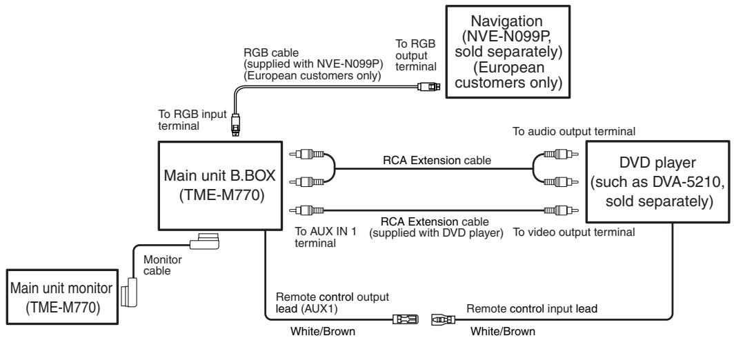
2) Main unit + navigation (NVE-N099P, European customers only) + DVD player (such as DVA-5210)
flowchart
graph TD
    A["Main unit monitor (TME-M770)"] -->|Monitor cable| B["Main unit B.BOX (TME-M770)"]
    B -->|RGB cable (supplied with NVE-N099P) (European customers only)| C["Navigation (NVE-N099P, sold separately) (European customers only)"]
    B -->|To AUX IN 1 terminal| D["RCA Extension cable"]
    D --> E["DVD player (such as DVA-5210, sold separately)"]
    B -->|To audio output terminal| F["Remote control input lead"]
    B -->|To RGB output terminal| G["Remote control output lead (AUX1)"]
    B --> H["White/Brown"]
    B --> I["White/Brown"]
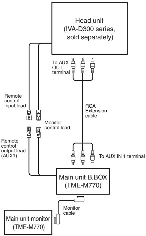
3) Main unit and head unit (IVA-D300 series)
flowchart
graph TD
    A["Head unit (IVA-D300 series, sold separately)"] --> B["Main unit B.BOX (TME-M770)"]
    B --> C["Monitor control lead"]
    B --> D["To AUX OUT terminal"]
    B --> E["To AUX IN 1 terminal"]
    B --> F["Monitor cable"]
    G["Main unit monitor (TME-M770)"] --> H["Remote control output lead (AUX1)"]
    H --> I["Remote control input lead"]
    I --> J["Monitor control lead"]
    J --> K["Head unit (IVA-D300 series, sold separately)"]
ALPINE®
Car Audio and Navigation Systems
GERÄTE-PASS
AUDIO SYSTEME
Filling in this Product Information Card is voluntary. If you fill in this card and send it to Alpine, your data will be tabulated into reference data for future Alpine product development. In addition, in the future you may receive information about new products or Survey Mail requesting additional opinions about Alpine products or services. If you agree to the above term, please sign your name in the indicated space and return the card. Any additional comments or inquiries may be sent to : Person in charge of Customer Service department Alpine Electronics (Europe) GmbH. Frankfurter Ring 117, 80807 München, Germany Phone: +49-(0)89-32 42 640
Q1. PRODUCT PURCHASED
- Cassette Player
- CD Player
- MD Player
- DVD Player
- CD Changer
- Amplifier
- Speaker
- Subwoofer
- Monitor Controller
- Video Monitor
- Navigation
- Processor/Equalizer
- CD/Video CD Changer
- Other
Q2. MODEL
NUMBER:
Q3. DATE OF PURCHASE:
Month:
Year:____
Q4. If navigation system, which monitor?
- Alpine → (Model No.)
- Other → (Brand Name)
Q5. STORE TYPE WHERE PURCHASED:
- Car Audio Specialist
- Audio/Video Store
- Electronics/Appliance Store
- Car Accessories Shop
- Other
Q6. Type of vehicle in which this unit is installed:
Make:
Model:
Purchased
Year:
Year:
Q7. How was this vehicle purchased?
- Purchase
- Lease
Q8. Purpose of buying this unit?
- Addition
- Replacement
|
• Previous brand replaced? - Factory installed
- Alpine
- Other → (Brand
Name)____
Q9. Have you purchased Alpine products before?
- First time
- Two or More times
Q10. When you purchased this Alpine unit, did you compare it with other brand?
- Yes → (Brand
Name)____ - No.
Q11.GENDER
- Male
- Female
Q12.AGE\_\_\_\_
Q13.MARITAL STATUS
- Single
- Married
Q14.OCCUPATION
- Company Owner/Self-employed/Freelance
- Manager
- Company Employee
- Civil Servant
- Educator
- Student
- Other
Q15.Comments\_\_\_\_
-
Addition
-
Remplacement
↓
text_image
Q3 Month Year | | | | | | | Q4 NO.1. Model No. NO.2. Brand Name| Q5 NO. Other | Q6 Make: Model: Purchased Year: | | | | ModelYear: | | | | |

text_image
Q7 NO. Q8 NO. 1 → Previous brand replaced. Brand Name 2 1. 2. 3. → _
text_image
Q9 NO. Q10 1→Brand Name NO. 2 ________ Q11 NO.
text_image
Q12 | | | years old Q13 NO. Q14 NO. Other| Q15 | Comments |
| _ |
LUFTPORT
PAR AVION
PRIORITAIRE

text_image
NE PAS AFFRANCHIR NICHT FREIMACHEN NO STAMP REQUIREDREPONSE PAYEE/ WERBEANTWORT ALLEMAGNE
ALPINE ELECTRONICS (EUROPE) GmbH Frankfurter Ring 117, 80807 München,
Germany