
RVCGM-80C - Car kit CRUX - Free user manual and instructions
Find the device manual for free RVCGM-80C CRUX in PDF.


| Brand | CRUX |
| Model | RVCGM-80C |
| Product Type | Rear View Camera Kit |
| Compatibility | GM vehicles with factory radio |
| Camera Dimensions | 30 mm x 30 mm x 25 mm |
| Weight | 100 g |
| Power Supply | DC 12V |
| Video Output | Composite RCA (NTSC) |
| Resolution | 480p (720 x 480) |
| Viewing Angle | 170° diagonal |
| Night Vision | Yes, IR LEDs |
| Waterproof Rating | IP67 |
| Operating Temperature | -20°C to 70°C |
| Installation Type | Surface mount or flush mount |
| Connection Type | RCA cable with 4-pin connector |
| Material | Aluminum housing, glass lens |
| Color | Black |
| Cable Length | 6 m (20 ft) |
| Warranty | 1 year limited |
| Included Parts | Camera, cable, mounting bracket, hardware |
| Maintenance | Clean lens with soft, dry cloth |
| Safety Features | Reverse trigger input, parking guidelines |
Frequently Asked Questions - RVCGM-80C CRUX
User questions about RVCGM-80C CRUX
0 question about this device. Answer the ones you know or ask your own.
Ask a new question about this device
Download the instructions for your Car kit in PDF format for free! Find your manual RVCGM-80C - CRUX and take your electronic device back in hand. On this page are published all the documents necessary for the use of your device. RVCGM-80C by CRUX.
USER MANUAL RVCGM-80C CRUX
- Automatically switches to rear-view when vehicle is put in reverse gear.
- Provides reverse camera input.
- Adds 3 Audio/Video inputs.
- Plug and play installation.
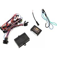
PARTS INCLUDED:

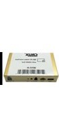
RVCGM-80C Module
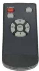
Remote Control Power Harness


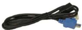

IR Extension Cable LVDS Cable A/V Cable

Camera Power Harness Push Button Switch

INSTALLATION DIAGRAM:
![graph TD A["Plug to HMI Module"] --> B["GM-80C LVDS T-HARNESS"] C["Connect to Blue Mini USB Plug from HMI Module"] --> B B --> D["Sightline Rear-View Integration"] D --> E["Fuse Box"] E --> F["+12V ACC"] E --> G["GROUND"] E --> H["PUSH BUTTON SWITCH"] E --> I["IR REMOTE CABLE"] E --> J["RGB CABLE"]…](/content/2026/05/997713/images/36e7771931cf0cb6b5fd60eb34f5190b6a3ab3e899e7ea6110a866e2ce38f5e2.jpg)
INSTALLATION INSTRUCTIONS:
Follow these steps to properly install the interface module. Note that this interface connects to the HMI Module.
- Remove the GLOVE BOX to gain access to the factory HMI module. The HMI module is located in different areas depending on the vehicle model. Below is a list of vehicles and where the HMI module can be located:
Cadillac ATS/CTS = below the glove box
Cadillac SRX = below or behind the glove box
Corvette = driver side kick panel
Once you have located the HMI module, unplug the BLUE LVDS connector. You will need to plug this to the RVCGM-80C Main Interface Module.

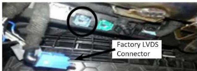
- Using the provided 24-Pin Power Harness, connect the loose wires on the 24-Pin as mentioned below. You can tap Accessory power from the cigarette lighter (+12V switched) position.
NOT ALL LOOSE WIRES ON THE 24-PIN CONNECTOR ARE USED
RED = Accessory
BLACK = Ground
BLUE = Parking
GRAY = Reverse Input
Factory Mini USB (LVDS)
connections are mostly
located on the MyLink
System box.
- After making the connections on the 24-Pin harness, insert the 24-Pin into the Main Interface module. Make sure that the connector is properly seated into the module.

3 of 8

Crux Interfacing Solutions • 6860 Canby Ave., Suite 116, Reseda, CA 91335 phone: (818) 609-9299 • fax: (818) 996-8188 • www.cruxinterfacing.com
rev.082718
After connecting the module, set the proper DIP switches to the "ON" position. Make sure to set the AV sources being used to the "ON" position. NOTE: The Video-In-Motion feature does not require activation. This feature is permanently ON and will not disturb the Navigation GPS performance.
MAIN INTERFACE
MODULE

DIP SWITCH DESCRIPTION

UP = ON

DOWN =
DIP 1 = ON = RGB Enable / OFF = Disable
DIP 2 = ON = AV1 Enable / OFF = Disable
DIP 3 = ON = AV2 Enable / OFF = Disable
DIP 4 = ON = AV3 Enable / OFF = Disable
DIP 5 = Not Used
DIP 6 = Not Used
DIP 7 = ON = Aftermarket Camera Enable
DIP 8 = Not Used
LED INDICATORS
DATA LINK STATUS:
Blinking = No BUS Detected.
Solid= BUSR ecognized.
OFF = Power Down / Sleep Mode.
POWER STATUS:
ON = Power On
OFF = Power Off
![graph TD A["POWER"] --> B["CAN-BUS"] C["DATALINK"] --> B B --> D["Output"] style B fill:#f9f,stroke:#333 style D fill:#ccf,stroke:#333](/content/2026/05/997713/images/11f13f45cbe39a18caa5f0ebee819f6072353c3e4ecb8fc0e35ff2ed66af9688.jpg)
NOTES:
- Before connecting the main module, set the proper DIP switch to the 'ON' position.
- Make sure to set the AV source being used to the 'ON' position.
- After each change of the DIP switch settings, we recommend powering down the module, then restarting the vehicle.
- The Video-In-Motion feature does not require activation. This feature is permanently ON and will not disturb the GPS performance.
CONNECTING THE CAMERA & AV INPUTS:
Follow these steps to properly install the CAMERA and other Devices to the interface module. (CAMERA NOT INCLUDED)
- Connect the 5-Pin Camera Power Cable to the module and use the RED and BLACK wires on this cable to power the rear-view camera. RED = +12V / BLACK = GROUND
- Connect the 24-Pin AV Input/Output Cable to the Main Interface module. Connect the Camera and other Devices to the inputs on this cable. See labels on the cables for descriptions. The AV outputs can be used to go to an external monitor.
Use the included 3.5 to RCA cable for the audio out to your factory AUX IN. (Interface requires radio to be on AUX input Mode)


OTHER CONNECTIONS:
These steps will help you with using the additional connectors on the main 24-Pin Power Harness.
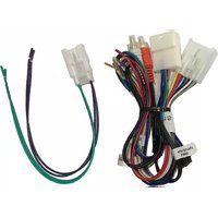
- Plug the factory BLUE Mini USB to the black female USB of the RVCGM-80C LVDS T-Harness. Insert the BLUE Mini USB of the RVCGM-80C LVDS T-Harness to the factory HMI module. Connect the 6-Pin RVCGM-80C LVDS T-Harness to the RVCGM-80C Main Interface Module.


NOTE ON CUE SYSTEMS:
If display does not show video, reverse the RED and WHITE wires on the 6-Pin RVCGM-80C LVDS T-Harness.
- Connect the 2-Pin Switch Cable if you are looking to switch the sources using the included switch. Connect the IR Remote if you would like to extend the IR Eye to a different location.
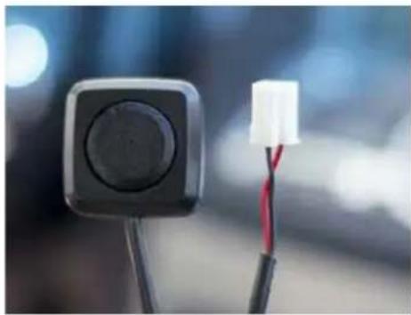

POWERING THE MODULE AND OTHER FEATURES
These steps will help you with connecting the loose wires.
- Connect the RED power wire to the ACC +12V on the cigarette lighter. GROUND the black wire to your desired location.
- Most of the loose wires are not required to be used. The most important wire to use is the GRAY (reverse input). Connect the GRAY wire to the reverse LAMP.
You can also use the BLUE wire on this harness to enable the AV INPUTS. Connect the BLUE wire to GROUND.


USING THE MENU OPTIONS ON IR REMOTE
These steps will help you with turning on certain features. Make sure the IR receiver is in a clear view for the IR Remote to contact.
- In order to access the Menus you must be in the AV source. Use the OK button on the IR remote to switch sources (same function as momentary switch included).
There are two menus on the interface. Use the arrows to navigate the menu. Press the MENU button on the Remote to access the main menu. See options below.


- To access the second menu set up, press and hold the left arrow for 3 seconds while in the AV source. This will bring you to a custom menu. Use the arrows to navigate the menu.
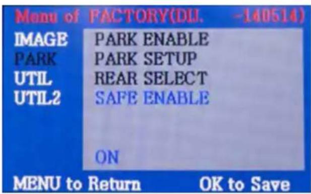
Make sure the safe enable is set to ON. This is in case you are not using the BLUE loose wire on the harness.
(Same function as BLUE wire)
Use the arrows to navigate the menu.
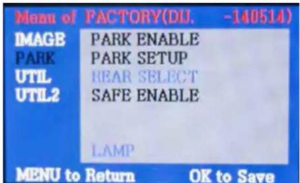
Make sure the REAR SELECT is set to LAMP; also make sure to connect the GRAY wire to the REVERSE LAMP wire.
Use the arrows to navigate the menu.
VEHICLE APPLICATIONS:
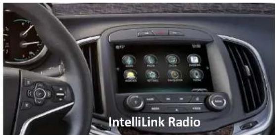
BUICK
| 2014 – 2015 | La Crosse |
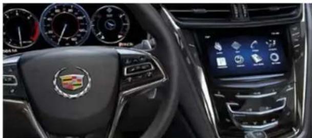
CADILLAC
| 2013 – 2015 | ATS |
| 2014 – 2015 | CTS Coupe |
| 2014 – 2015 | CTS/CTS V |
| 2015 | Escalade |
| 2013 – 2015 | SRX |
| 2013 – 2015 | XTS |
CHEVROLET
| 2014 – 2015 | Avalanche |
| 2014 – 2015 | Impala |
| 2015 – 2015 | Malibu |
| 2014 – 2015 | Silverado |
| 2015 – 2015 | Suburban |
| 2015 – 2015 | Tahoe |
GMC
| 2015 | Canyon |
| 2014 – 2015 | Sierra Pickup |
| 2014 – 2015 | Yukon |

8 of 8

Crux Interfacing Solutions • 6860 Canby Ave., Suite 116, Reseda, CA 91335
phone: (818) 609-9299 • fax: (818) 996-8188 • www.cruxinterfacing.com
rev.082718

Brand : CRUX
Model : RVCGM-80C
Category : Car kit