
WVIMB-06 - Car kit CRUX - Free user manual and instructions
Find the device manual for free WVIMB-06 CRUX in PDF.

| Product Type | Vehicle Interface Module (Retrofit Kit) |
| Brand | CRUX |
| Model | WVIMB-06 |
| Compatible Vehicles | Mercedes-Benz: B-Class (W246 2013), C-Class (W204/C204 2012-2013), E-Class (W212 2012-2013, C207 2012-2014), CLS (C218 2012-2013), GLK (W204 2011-2013), ML (W166 2012-2013), SLK (R172 2012), SL (R231 2013) |
| Radio Compatibility | NTG4.5 Navigation Radios with Multi-Changer icon |
| Power Supply | +12V ACC (Ignition) and Ground |
| Power Consumption | Approximately 5W (typical) |
| Dimensions (Module) | Approximately 3.5 x 2.5 x 1.0 inches |
| Weight | Approximately 0.5 lbs |
| Video Input | Composite AV (RCA) via VC-85 cable, plus WiFi mirroring |
| Video Output | 2 RCA composite outputs, HDMI output (cable not included) |
| WiFi Module | Built-in for smartphone mirroring (AirPlay for iOS, Miracast for Android) |
| Video In Motion (VIM) | Built-in; DIP switch 1 enables, DIP 5&6 for CAN-Bus configuration |
| Rear View Camera | Supported; automatically prioritizes when reverse engaged |
| Online Navigation | Via smartphone mirroring (e.g., Google Maps, Waze) |
| DRM Content | Netflix and similar DRM-protected videos not supported on iOS due to Apple restrictions |
| Installation | Plug-and-play T-harness; requires removal of factory radio and fiber optic cable relocation |
| DIP Switches | 6 switches: 1=Video In-Motion, 2-4=Not Used, 5&6=CAN-Bus (default OFF, turn ON if no display while moving) |
| LED Indicators | Blue: Blinking=No BUS, Solid=BUS recognized, OFF=Sleep; Red: ON=Power, OFF=Power OFF |
| Included Parts | WVIMB-06 Module, MB-06 Harness, AV Adapter (VC-85), WVI-X WiFi Module |
| Maintenance | Keep connectors clean; update firmware if available (not specified) |
| Safety | Do not use while driving to avoid distraction; follow local laws |
| Spare Parts & Repairability | Contact CRUX for replacement parts; module not user-serviceable |
Frequently Asked Questions - WVIMB-06 CRUX
User questions about WVIMB-06 CRUX
0 question about this device. Answer the ones you know or ask your own.
Ask a new question about this device
Download the instructions for your Car kit in PDF format for free! Find your manual WVIMB-06 - CRUX and take your electronic device back in hand. On this page are published all the documents necessary for the use of your device. WVIMB-06 by CRUX.
USER MANUAL WVIMB-06 CRUX
Vehicle Applications
Now Streams YouTube Videos from iOS Devices!
MERCEDES BENZ
2013 - 2013 B-class (W246)
2012 - 2013 C-class (W204)
2012 - 2013 C-class (C204)
2012 - 2013 E-class (W212)
2012 - 2014 E-class (C207)
2012 - 2013 CLS (C218)
2011 - 2013 GLK (W204)
2012 - 2013 ML (W166)
2012-2013 SLK(R172)
2013 - 2013 SL (R231)
Features
- Works on NTG4.5 Navigation Radios.
- Built-in VIM capability for A/V sources.
- Does not conflict with Rear-View camera. RVC automatically takes priority.
- Does not conflict with Factory GPS or other OEM features.
- Online navigation via Smartphone Mirroring.
- WiFi module includes 2 video outputs for multiple screen applications.
Notes
- Radio MUST have Multi Changer icon.
- Does NOT support Netflix or other videos with DRM content on iOS devices due to Restrictions placed by Apple.
- Crux part# VCIP5 cable may be utilized for accessing these Apps (Sold Separately).
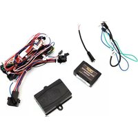
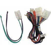
Parts Included


natural_image
Pure electrical connector diagram without any text or symbols
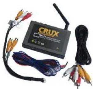
natural_image
Electronic device labeled 'CRUX' with multiple cables and connectors (no readable text beyond branding)WVIMB-06 Module MB-06 Harness AV Adapter WVI-X WiFi Module
rev.082816
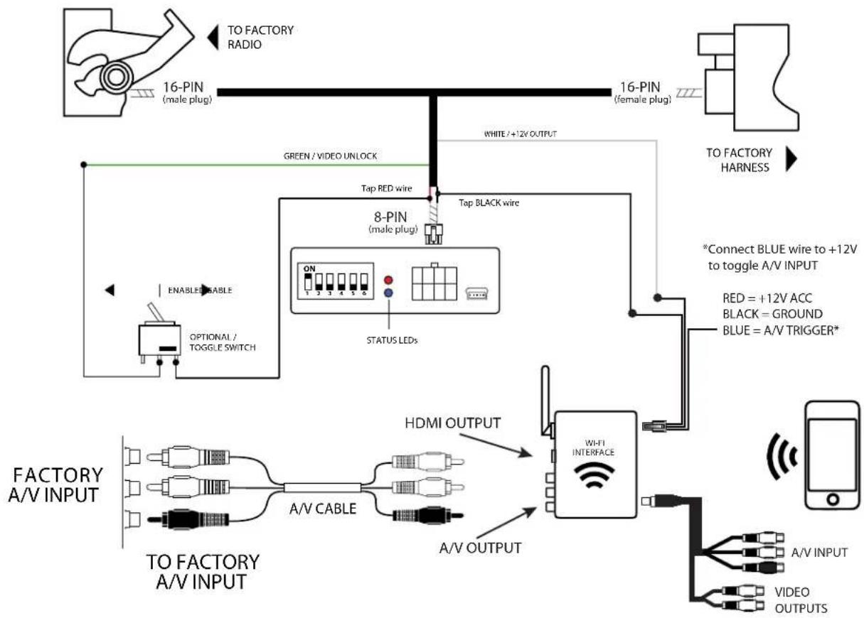
flowchart
graph TD
    A["TO FACTORY RADIO"] --> B["16-PIN (male plug)"]
    B --> C["GREEN / VIDEO UNLOCK"]
    C --> D["Tap RED wire"]
    D --> E["8-PIN (male plug)"]
    E --> F["TAP BLACK wire"]
    F --> G["STATUS LEDs"]
    G --> H["FI INTERFACE"]
    H --> I["A-V INPUT"]
    H --> J["A-V OUTPUT"]
    K["ENABLED/ABLE"] --> L["OPTIONAL / TOGGLE SWITCH"]
    L --> M["HDMI OUTPUT"]
    M --> N["FI INTERFACE"]
    O["TO FACTORY HARNESS"] --> P["TO FACTORY RADIO"]
    Q["*Connect BLUE wire to +12V to toggle A/V INPUT"] --> R["RED = +12V ACC\nBLACK = GROUND\nBLUE = A/V TRIGGER*"]
    S["VIDEO OUTPUTS"] --> T["A-V INPUT"]
    S --> U["A-V OUTPUT"]
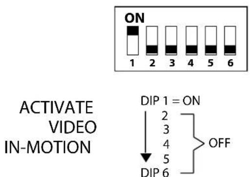
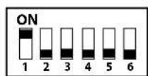
DIP SWITCHES OVERVIEW
RADIO MUST HAVE MULTI-DISC CHANGER ICON

CONNECTING THE INTERFACE
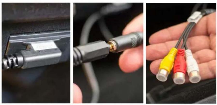
Step 1 - Remove the factory radio to gain access to the factory 16-Pin connector. Disconnect the factory 16-Pin connector from the radio.

natural_image
Interior view of a Mercedes-Benz car dashboard and infotainment system (no visible text or symbols)Step 2 - On the factory 16-Pin connector, remove the factory FIBER OPTIC cables from the harness. With the Fiber Optic cables removed, re-insert them into the our 16-Pin T-Harness male connector. (See location below)

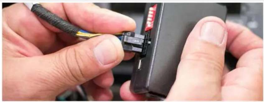
Step 3 - Mate the T-Harness to the factory harness, then to the radio side. Be sure to lock the harness for a secure connection.

natural_image
Close-up of a hand holding a black plastic electrical connector with wires, no visible text or symbols3/6
rev.082816
Crux Interfacing Solutions
www.cruxinterfacing.com

tel. #: (818) 609-9299
fax #: (818) 996-8188
Step 4 - Locate your factory AUX input cable, then using the provided VC-85 A/V Cable, connect the cable to your factory MEDIA AUX input. This cable will provide you access to the factory A/V input.
Step 5 - Connect the 8-Pin connector on the provided T-Harness to the main interface module. Make sure all your connections are firmly inserted.
natural_image
Close-up of hands inserting a black cable to a device with red LED connectors (no text or symbols visible)DIP SWITCH SETTINGS
ACTIVATE
VIDEO
IN-MOTION
DIPS 5 & 6: These two dip switches control the CAN-Bus con guration.
Switches "5" and "6" are defaulted to "OFF", test the video in-motion, If there is no display on the screen while the vehicle is in motion, please place switches "5" and "6" to "ON".
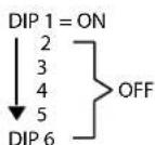
DIP SWITCH DESCRIPTION
Up = ON, Down = OFF
DIP 1 = Video In-Motion (Always On) DIP 2 = Not Used
DIP 3 = Not Used
DIP 4 = Not Used
DIP 5 = Not Used
DIP 6 = Not Used
LED INDICATORS
BLUE LED:
Blinking = No BUS Detected.
Solid = BUS Recognized.
OFF = Power Down/ Sleep mode.
RED LED:
ON = Power On
OFF = Power OFF
After each change of the DIP switch settings, we recommend powering down the module, then restarting the module.
rev.082816
Crux Interfacing Solutions
www.cruxinterfacing.com

tel. #: (818) 609-9299
fax #: (818) 996-8188
CONNECTING THE WiFi MODULE
The T-harness provides a WHITE wire for +12V ACC to be used on the Wi-Fi module. Connect the RED wire from the 8-Pin Wi-Fi harness to the WHITE wire coming off the T-harness. Connect the BLACK wire from the Wi-Fi harness to the BLACK wire on the 8-Pin connector. See below.

flowchart
graph TD
    A["8-PIN (male plug)"] -->|White / -12V OUTPUT| B["Tap BLACK wire"]
    B --> C["Wi-Fi INTERFACE"]
    C --> D["A/V INPUT"]
    C --> E["VIDEO OUTPUTS"]
    C --> F["RED = +12V ACC"]
    C --> G["BLACK = GROUND"]
    C --> H["BLUE = A/V TRIGGER*"]
    style A fill:#f9f,stroke:#333
    style B fill:#ccf,stroke:#333
    style C fill:#cff,stroke:#333
    style D fill:#ffc,stroke:#333
    style E fill:#cfc,stroke:#333
    style F fill:#fcc,stroke:#333
    style G fill:#fcc,stroke:#333
    style H fill:#fcc,stroke:#333
- Screw on the antenna to the interface.
- Connect the BLUE wire to +12V to trigger the AV input feature. The AV INPUT can be connected to an AV source with composite output. A toggle switch (not included), wired between the BLUE wire and +12V can be used to switch ON or OFF the AV INPUT feature. The AV INPUT can also be used for a rear-view camera option. Connect the BLUE wire to the reverse light +12V lead to toggle this feature.
- The WVIGM-04 also offers 2 RCA video outputs for multiple monitor set-ups.
- An HDMI video output is available for HD video resolution. HDMI cable is not included in the kit.
- Switch to the new AV input by using the SWC or the radio.
- Test the interface and re-install the radio into the dash.
To select the AUX source simply enter the AUDIO TAB menu and select AUX.

5/6
rev.082816
SETTING YOUR DEVICE
With the Interface ON and READY:


AirPlay
On the iOS 7 and up:
Swipe your finger from the bottom up on the iPhone or iPad. From the Quick Menu, turn ON the WiFi. Open SETTINGS and go to Wi-Fi and connect to "WiFi Car xxx". Press home button to go back to to the Home screen. Swipe your finger from the bottom up again to open drawer. Tap on AIR PLAY and turn on MIRRORING.


For the Android system:
Tap the Menu button at the top of your screen and select Enable wireless display. Your phone will scan for nearby Miracast devices and display them in a list under Cast Screen.
MIRRORING:
The mirroring connection uses a direct WiFi connection to transfer the Audio and Video from your device to the OE monitor. This does not require an active network.
If your smartphone has the Screen Time Out enabled and your display goes to sleep mode, you will no longer see the image on the screen. Deactivate this feature for continuous viewing.

natural_image
Diagram showing a hand interacting with a smartphone inside a car dashboard, with no visible text or symbols.COMPATIBLE RADIOS
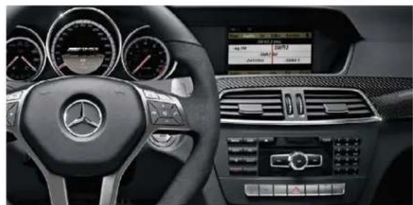
natural_image
Interior view of a Mercedes-Benz car dashboard and steering wheel (no visible text or symbols)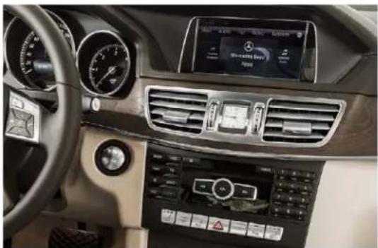
natural_image
Interior view of a luxury car dashboard with air conditioners, controls, and a digital display (no visible text or symbols)6/6
rev.082816
Crux Interfacing Solutions
www.cruxinterfacing.com

tel. #: (818) 609-9299
fax #: (818) 996-8188


Brand : CRUX
Model : WVIMB-06
Category : Car kit