
EN1751 - Detector Inovonics - Free user manual and instructions
Find the device manual for free EN1751 Inovonics in PDF.


| Product Type | Wireless Detector |
| Brand | Inovonics |
| Model | EN1751 |
| Category | Detector |
| Dimensions (H x W x D) | 2.6 x 3.2 x 1.2 inches (66 x 81 x 30 mm) |
| Weight | 3 oz (85 g) |
| Power Source | 1 x 3V CR123A lithium battery |
| Battery Life | Up to 5 years typical |
| Wireless Protocol | EchoStream 900 MHz |
| Range (Open Field) | Up to 2,000 ft (610 m) |
| Operating Temperature | 32°F to 120°F (0°C to 49°C) |
| Humidity Range | 5% to 95% non-condensing |
| Tamper Protection | Cover tamper switch |
| LED Indicator | Red/green for status |
| Supervision | Check-in signal every 4 hours |
| Compatibility | Inovonics receivers and panels |
| Mounting | Screws or adhesive pads (included) |
| Maintenance | Wipe with a soft, dry cloth; avoid liquids |
| Repairability | Battery replaceable; no user-serviceable parts |
| Safety & Security | Low battery notification; tamper alarm |
Frequently Asked Questions - EN1751 Inovonics
User questions about EN1751 Inovonics
0 question about this device. Answer the ones you know or ask your own.
Ask a new question about this device
Download the instructions for your Detector in PDF format for free! Find your manual EN1751 - Inovonics and take your electronic device back in hand. On this page are published all the documents necessary for the use of your device. EN1751 by Inovonics.
USER MANUAL EN1751 Inovonics
EN1751 Water Detector
Installation Instructions
1 Overview
The EN1751 water detector provides affordable early warning against damage caused by leaking appliances and standing water when used with the Honeywell® FP280 or compatible probes from Flair Electronics®, sold separately. The EN1751 water detector sends a primary alarm (alarm 1) to indicate the presence of water, and a secondary and tertiary alarm (alarm 2 and alarm 3) to indicate other fault conditions described in section 4, "Operation" on page 2.
1.1 Inovonics Contact Information

For product and installation videos visit us at www.inovonics.com/videos or use the QR code below.

If you have any problems with this procedure, contact Inovonics Wireless technical services:
• E-mail: support@inovonics.com
• Phone: (800) 782-2709
1.2 Water Detector Internal Components
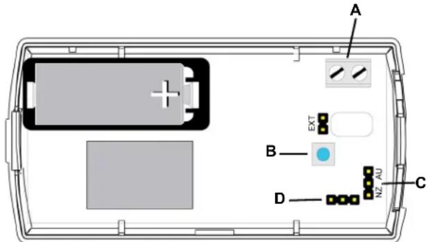
Figure 1 Water detector internal components
A Terminal block
B Reset button
C Frequency band selection pins
D Programming header
2 Installation and Startup
2.1 Installation Notes
• These products are designed to be installed and maintained by professional security technicians.
- Products are intended for indoor use.
- Manually test all products weekly.
2.2 Install the Battery
- Pry the top lip of the mounting bracket up, and lift the bracket off of the transmitter.
- Use your thumb to depress the housing release tab on the bottom of the transmitter; separate the housing.
- Install the new battery.
- Press the reset button to initialize the transmitter.
2.3 Mount the Probe
The Inovonics EN1751 water detector is used with the Honeywell FP280 or Flair Electronics® 1010-H2OS36-EN1751 probe. To mount the external probe:
- Trim the probe wiring to the desired length.
- Route the probe wiring through either the rectangular back wiring cutouts on the back of the housing and bracket, or through the rounded top wiring cutout at the top of the housing.
Note: If you want to use the cutout at the top of the housing, you will need to trim the bracket.
-
Use a small screwdriver to attach the probe wiring leads to the power terminal block.
-
Mount the probe per manufacturer's instructions.
-
Press the reset button to complete configuration.
2.4 Select the Frequency Band
EchoStream products are able to use a range of radio frequencies, and is shipped from Inovonics set for your geographic area.
- The jumper will be set on the two pins marked NZ to set the frequency range to 921-928 MHz for New Zealand.
- The jumper will be set on the two pins marked AU to set the frequency range to 915-928 MHz for Australia.
-
The jumper will be removed to set the frequency band to 902-928 MHz for North America.
-
Ensure the frequency band is set for your geographic are.
-
If the frequency band is not set for your geographic area, place a selection jumper on the appropriate frequency band selection pins to select Australia or New Zealand, or remove it for North America.
-
If you have changed the frequency band, press the reset button to complete configuration.
Caution: When pressing the reset button, make sure you don't also touch the frequency band selection pins. Touching the frequency band selection pins while pressing the reset button can inadvertently set the single input universal transmitter to the wrong frequency band.
2.5 Program the Transmitter
EN1751 transmitters are programmed at the factory. It is not usually necessary to reprogram EN1751 transmitters. If you want to reprogram the transmission interval, the parameter can be changed using the programming header and the ACC17XX programming cable. Contact Inovonics technical services for details.
2.6 Register the EN1751 Water Detector
The EN1751 water detector must be registered with the system in order to be monitored and supervised. Refer to the receiver installation instructions for details on registering a transmitter.
- When prompted by the receiver to reset transmitter, press the reset button.
- Replace the cover.
2.7 Mount the EN1751 Water Detector
- Attach the mounting bracket to the desired location, using the included screws or double-sided tape.
Note: There are two mounting holes for standard installation. An optional third mounting hole is located under the battery. Use the third mounting hole to secure the housing to the bracket.
- Hook the bottom of the EN1751 water detector into the bracket's bottom catch, and press the EN1751 into the bracket so that the bracket's top lip snaps into place.
- Use staples or tape to secure the wiring between the EN1751 water detector and the probe.
- Test the EN1751 and probe per section 3, "Testing the EN1751 Water Detector".
3 Testing the EN1751 Water Detector
The EN1751 water detector should be tested weekly and after registration to ensure operation.
To test the EN1751 water detector:
-
Inspect to ensure both the EN1751 and probe are securely mounted and the wiring is still secured.
-
Submerge the probe in 1/4" of non-distilled water and ensure an appropriate response.
When testing has completed, you will need to reset the EN1751. To reset the EN1751:
-
Remove the EN1751 water detector from the mounting bracket.
-
Use your thumb to depress the housing release tab on the bottom of the transmitter; separate the housing.
-
Press the reset button.
-
Replace the housing and return the transmitter to the mounting bracket.
4 Operation
The primary alarm, alarm 1, is sent when the EN1751 detects water; the other two alarms, alarm 2 and alarm 3, as well as the tamper message, are sent in the following cases:
| Condition Message | |
| Ambient temperature at or above 140°F. | The alarm 2 message will be sent. |
| Ambient temperature at or below -4°F. | The alarm 3 message will be sent. |
| Probe disconnected from Inovonics EN1751 water detector | The tamper message will be sent. |
Note: If an alarm 1 message is sent and no water is present, inspect the wiring at the probe terminal block to ensure that there is no short.
Note: The EN1751 water detector cannot reliably detect frozen water.
5 Specifications
Dimensions: EN1751: 3.5" x 1.7" x 0.9"; FP280: 1.5" x 1.0" x 0.375". Battery type: BAT604, Panasonic CR123A or equivalent, rated 3VDC.
Typical battery life: 8 years at a 5 minute transmission interval.
Operating temperature: -4^ to 140^ F.
Humidity: 0 to 90%, non-condensing.
Operating frequency: 902-928 MHz.
Regulatory compliance: FCC; RoHs compliant; Industry Canada; RCM.
Note: The transmitter output power level is the same for North America, Australia and New Zealand.
Note: Inovonics supports recycling and reuse whenever possible. Please recycle these parts using a certified electronics recycler.
Note: Specifications and data are subject to change without notice.
Caution: Changes or modifications not expressly approved by Inovonics could void your authority to operate the equipment.
6 Television and Radio Interference
This equipment has been tested and found to comply with the limits for a Class B digital device, pursuant to Part 15 of the FCC Rules. These limits are designed to provide reasonable protection against harmful interference in a residential installation. This equipment generates, uses and can radiate radio frequency energy and, if not installed and used in accordance with the instructions, may cause harmful interference to radio communications. However, there is no guarantee that interference will not occur in a particular installation. If this equipment does cause harmful interference to radio or television reception, which can be determined by turning the equipment off and on, the user is encouraged to try to correct the interference by one or more of the following measures:
- Reorient or relocate the receiving antenna.
-
Increase the separation between the equipment and receiver.
-
Connect the equipment into an outlet on a circuit different from that to which the receiver is connected.
- Consult the dealer or an experienced radio/TV technician for help.
7 FCC Part 15 and Innovation, Science and Economic Development Canada (ISED) Compliance
This device complies with part 15 of the FCC Rules, and ISED license-exempt RSS standard(s). Operation is subject to the following two conditions: (1) this device may not cause interference, and (2) this device must accept any interference that may cause undesired operation of the device.
8 Radiation Exposure Limits
8.1 FCC
This equipment complies with FCC radiation exposure limits set forth for an uncontrolled environment. In order to avoid the possibility of exceeding the FCC radio frequency exposure limits, human proximity to the antenna shall not be less than 20 cm during normal operation and must not be co-located or operating in conjunction with any other antenna or transmitter.
8.2 ISED
This equipment complies with ISED RSS-102 radiation exposure limits set forth for an uncontrolled environment. This transmitter must be installed to provide a separation distance of at least 20 cm from all persons and must not be co-located or operating in conjunction with any other antenna or transmitter.
- EN1751 Water Detector
- Installation Instructions
- Overview
- Inovonics Contact Information
- Water Detector Internal Components
- Installation and Startup
- Installation Notes
- Install the Battery
- Mount the Probe
- Select the Frequency Band
- Program the Transmitter
- Register the EN1751 Water Detector
- Mount the EN1751 Water Detector
- Testing the EN1751 Water Detector
- Operation
- Specifications
- Television and Radio Interference
- FCC Part 15 and Innovation, Science and Economic Development Canada (ISED) Compliance
- Radiation Exposure Limits
- FCC
- ISED
Brand : Inovonics
Model : EN1751
Category : Detector