SS10TDU - Plate warmer Wells - Free user manual and instructions
Find the device manual for free SS10TDU Wells in PDF.


| Product Type | Plate Warmer |
| Brand | Wells |
| Model | SS10TDU |
| Dimensions (W x D x H) | 30 x 20 x 10 inches (approx.) |
| Weight | 25 lbs (approx.) |
| Power Source | Electric, 120V, 60Hz |
| Wattage | 1000W |
| Material | Stainless steel construction |
| Temperature Control | Adjustable thermostat with dial |
| Temperature Range | 150°F - 200°F (approx.) |
| Indicator Light | Power-on indicator |
| Heating Element | Even-heating element under top surface |
| Capacity | Holds up to 24 standard dinner plates |
| Usage | Commercial or heavy-duty residential |
| Cleaning | Wipe with a damp cloth; do not immerse |
| Safety Features | Thermostat with auto shut-off, insulated feet |
| Certifications | ETL or UL listed (est.) |
| Warranty | 1 year limited warranty (typical) |
Frequently Asked Questions - SS10TDU Wells
User questions about SS10TDU Wells
0 question about this device. Answer the ones you know or ask your own.
Ask a new question about this device
Download the instructions for your Plate warmer in PDF format for free! Find your manual SS10TDU - Wells and take your electronic device back in hand. On this page are published all the documents necessary for the use of your device. SS10TDU by Wells.
USER MANUAL SS10TDU Wells
SEE CONDITIONS OF ACCEPTIBILITY BELOW
WHEN CONTROL BOX IS LOCATED BELOW THE UNIT, FRONT CLEARANCE CAN BE 2 INCHES.
NOTE: DEPENDING ON THE INSTALLATION, CLEARANCES CAN BE FURTHER REDUCED UPON EVALUATIONS TO UL STANDARDS.
CUTOUT DETAILS
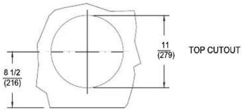
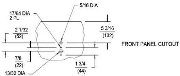
INCHES (MM)
PRODUCT DIMENSIONS
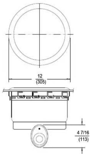
NOTE: * CONTROL MUST NOT BE MOUNTED IN THIS HIGH TEMPERATURE AREA.
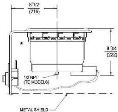
INSTALLATION INSTRUCTIONS
UNIT MUST BE INSTALLED IN AN ALL METAL COUNTER. THE INSTALLATION OF RECOGNIZED COMPONENT UNITS REQUIRES ADDITIONAL EVALUATIONS TO UNDERWRITERS LABORATORIES INC. STANDARDS.
INSTALLER MUST MEET CONDITIONS OF ACCEPTABILITY OUTLINED BELOW UPON INSTALLATION:
- This appliance shall be installed in an all metal counter with suitable wiring and control enclosures conforming to national and local electrical codes.
- Electrical component temperatures, including wiring, within and surrounding the appliance must be monitored in the end use installation for suitability.
- Electrical grounding of all dead metal parts must be reliably connected to the grounding means of the appliance and must comply with the requirements outlined in the appropriate Underwriters Laboratories Inc. classification, national and local electrical codes.
- Increased clearances are required if storage of combustible materials is in close proximity to this appliance.
- Unit shall be accessible for servicing from the bottom.
- The name/rating plate information shall be accessible.
- For water and waste connections: This appliance is to be installed to comply with the applicable federal, state or local plumbing codes.
TO FABRICATE:
- Lay out "cutout" dimensions on countertop and front apron as shown in cutout details above.
- Cut and/or drill holes as required in countertop and
- Must be accessible for servicing from the bottom.
TO INSTALL:
IMPORTANT - DO NOT disconnect lead wires from the Control Panel when installing.
- Locate the warmer and control panel over the countertop cutout. Pass the control through the opening, then mount the control to the rear of the apron.
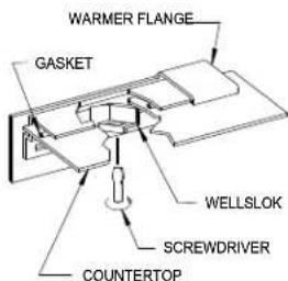
- Apply a bead of silicone adhesive/sealant to the gasket supplied on the underside of the warmer flange, then seat the warmer onto the countertop. Properly position.
- From underneath, insert a screwdriver into the "slots" on the wellslok frame and twist the "ears" outward to secure the flange tightly to the countertop (see detail).
- Mount the master control panel to the front of the counter apron using the screws supplied.
Brand : Wells
Model : SS10TDU
Category : Plate warmer