HSW6D - Food Warmer Wells - Free user manual and instructions
Find the device manual for free HSW6D Wells in PDF.


| Product Type | Built-In Plate Warmer (Hot Food Holding) |
| Model | HSW6D |
| Brand | Wells |
| Voltage | 120 VAC, Single Phase |
| Amperage | 2.9 A |
| Wattage | 350 W |
| Power Cord | Not specified (hardwired or cord & plug depending on model) |
| Control Type | Thermostatic (rotary knob with OFF position) |
| Indicator Light | Yes, glows when heating element is energized |
| Mounting | Top-mounted, built-in with Wellslok turnout tabs |
| Drain | Yes, suffix "D" indicates individual drain for each pan |
| Operation Mode | Wet or Dry (do not switch while hot) |
| Construction Material | Stainless steel (#304DDQ for pans) |
| Cutout Dimensions | Refer to installation instructions (not provided in manual) |
| Warranty | 1 year from original installation or 18 months from shipment |
| Standards Compliance | NSF Standard 4, UL Listed (File E6070) |
| Usage Environment | Commercial establishment only |
| Daily Cleaning | Mild detergent and vinegar solution; no steel wool |
| Weekly Maintenance | Deliming with commercial cleaner if scale builds up |
| Shock Hazard | Disconnect power before cleaning; do not splash water on controls |
| Service | Authorized Wells service agency required for repairs |
Frequently Asked Questions - HSW6D Wells
User questions about HSW6D Wells
0 question about this device. Answer the ones you know or ask your own.
Ask a new question about this device
Download the instructions for your Food Warmer in PDF format for free! Find your manual HSW6D - Wells and take your electronic device back in hand. On this page are published all the documents necessary for the use of your device. HSW6D by Wells.
USER MANUAL HSW6D Wells
natural_image
Exterior view of a stainless steel model HSW6 appliance connected to a coiled heating element (no text or symbols on the device itself)MODELS
HSW6
HSW6D
THIRD SIZE
with FIXED
THERMOSTAT
TSW6D
Includes
INSTALLATION
USE & CARE
EXPLODED VIEW
PARTS LIST
WIRING DIAGRAM
IMPORTANT: DO NOT DISCARD THIS MANUAL
This manual is considered to be part of the appliance and is to be given to the OWNER or MANAGER of the restaurant, or to the person responsible for TRAINING OPERATORS of this appliance. Additional manuals are available from your WELLS DEALER.
THIS MANUAL MUST BE READ AND UNDERSTOOD BY ALL PERSONS USING OR INSTALLING THIS APPLIANCE. Contact your WELLS DEALER if you have any questions concerning installation, operation or maintenance of this equipment.

natural_image
Silhouette of a person reading a book (no text or symbols visible)LIMITED WARRANTY STATEMENT
Unless otherwise specified, all commercial cooking equipment manufactured by Wells Manufacturing is warranted against defects in materials and workmanship for a period of one year from the date of original installation or 18 months from the date of shipment from our factory, whichever comes first, and is for the benefit of the original purchaser only.
THIS WARRANTY IS THE COMPLETE AND ONLY WARRANTY, EXPRESSED OR IMPLIED IN LAW OR IN FACT, INCLUDING BUT NOT LIMITED TO, WARRANTIES OF MERCHANTABILITY OR FITNESS FOR ANY PARTICULAR PURPOSE, AND/OR FOR DIRECT, INDIRECT OR CONSEQUENTIAL DAMAGES IN CONNECTION WITH WELLS BLOOMFIELD PRODUCTS. This warranty is void if it is determined that, upon inspection by an authorized service agency, the equipment has been modified, misused, misapplied, improperly installed, or damaged in transit or by fire, flood or act of God. It also does not apply if the serial nameplate has been removed, or if service is performed by unauthorized personnel.
The prices charged by Wells Manufacturing for its products are based upon the limitations in this warranty. Seller's obligation under this warranty is limited to the repair of defects without charge by a Wells Manufacturing factory authorized service agency or one of its sub-service agencies. This service will be provided on customer's premises for non-portable models. Portable models (a device with a cord and plug) must be taken or shipped to the closest authorized service agency, transportation charges prepaid, for service. In addition to restrictions contained in this warranty, specific limitations are shown in the Service Policy and Procedure Guide. Wells Manufacturing authorized service agencies are located in principal cities. This warranty is valid in the United States and Canada and void elsewhere. Please consult your classified telephone directory, your foodservice equipment dealer or contact:
Wells Manufacturing
10 Sunnen Dr., St. Louis MO 63143 USA
phone (314) 678-6314 or fax (314) 781-2714
for information and other details concerning warranty.
SERVICE POLICY AND PROCEDURE GUIDE and ADDITIONAL WARRANTY EXCLUSIONS
- Resetting of safety thermostats, circuit breakers, over load protectors, and/or fuse replacements are not covered by this warranty unless warranted conditions are the cause.
- All problems due to operation at voltages or phase other than specified on equipment nameplates are not covered by this warranty. Conversion to correct voltage and/or phase must be the customer's responsibility.
- All problems due to electrical connections not made in accordance with electrical code requirements and wiring diagrams supplied with the equipment are not covered by this warranty.
- Replacement of items subject to normal wear, to include such items as knobs, light bulbs; and, normal maintenance functions including adjustments of thermostats, adjustment of micro switches and replacement of fuses and indicating lights are not covered by warranty.
- Damage to electrical cords and/or plug due to exposure to excessive heat are not covered by this warranty.
- Full use, care, and maintenance instructions supplied with each machine. Noted maintenance and preventative maintenance items, such as servicing and
cleaning schedules, are customer responsibility. Those miscellaneous adjustments noted are customer responsibility. Proper attention to preventative maintenance and scheduled maintenance procedures will prolong the life of the appliance.
7. Travel mileage is limited to sixty (60) miles from an Authorized Service Agency or one of its sub-service agencies.
8. All labor shall be performed during regular working hours. Overtime premium will be charged to the buyer.
9. All genuine Wells replacement parts are warranted for ninety (90) days from date of purchase on non-warranty equipment. This parts warranty is limited only to replacement of the defective part(s). Any use of non-genuine Wells parts completely voids any warranty.
10. Installation, labor, and job check-outs are not considered warranty and are thus not covered by this warranty.
11. Charges incurred by delays, waiting time or operating restrictions that hinder the service technician's ability to perform service are not covered by warranty. This includes institutional and correctional facilities.
SHIPPING DAMAGE CLAIM PROCEDURE
NOTE: For your protection, please note that equipment in this shipment was carefully inspected and packaged by skilled personnel before leaving the factory. Upon acceptance of this shipment, the transportation company assumes full responsibility for its safe delivery.
IF SHIPMENT ARRIVES DAMAGED:
-
VISIBLE LOSS OR DAMAGE: Be certain that any visible loss or damage is noted on the freight bill or express receipt, and that the note of loss or damage is signed by the delivery person.
-
FILE CLAIM FOR DAMAGE IMMEDIATELY: Regardless of the extent of the damage.
-
CONCEALED LOSS OR DAMAGE: if damage is unnoticed until the merchandise is unpacked, notify the transportation company or carrier immediately, and file "CONCEALED DAMAGE" claim with them. This should be done within fifteen (15) days from the date the delivery was made to you. Be sure to retain the container for inspection.
Wells Manufacturing cannot assume liability for damage or loss incurred in transit. We will, however, at your request, supply you with the necessary documents to support your claim.
TABLE OF CONTENTS
WARRANTY xi
FEATURES & OPERATING CONTROLS 2
PRECAUTIONS & GENERAL INFORMATION 3
AGENCY LISTING INFORMATION 3
INSTALLATION 4
OPERATION 6
MAINTENANCE INSTRUCTIONS 7
CLEANING INSTRUCTIONS 8
TROUBLESHOOTING SUGGESTIONS 10
WIRING DIAGRAM 11
EXPLODED VIEW & PARTS LIST 12 - 15
PARTS & SERVICE 17
CUSTOMER SERVICE DATA 17
INTRODUCTION
Thank You for purchasing this Wells Manufacturing appliance.
Proper installation, professional operation and consistent maintenance of this appliance will ensure that it gives you the very best performance and a long, economical service life.
This manual contains the information needed to properly install this appliance, and to use and care for the appliance in a manner which will ensure its optimum performance.
SPECIFICATIONS
ELECTRICAL SPECIFICATIONS
| MODEL VOL | TS AMPS | WATTS | POWER SUPPLY | CORD |
| HSW6 | 120 VAC 1 | 6.9A | 825W | |
| HSW6D | ||||
| TSW6D | 2.9A | 350W | ||
FEATURES & OPERATING CONTROLS
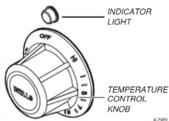
A. THERMOSTAT
- On thermostatically controlled warmers, power is applied to the heating element according to the control knob position and the actual temperature at the temperature sensing thermobulb.
- The desired temperature is controlled by rotating the temperature control knob. The knob has a numeric scale, where higher numbers correspond to higher temperature.
- On warmers equipped with an indicator light, the light will glow when the thermostat is calling for heat (i.e. the element is energized).
- The TEMPERATURE CONTROL KNOB will rotate approximately 300^ , and will reach a “stop” at both ends. The OFF position is marked.
NOTE: The dial position is an indication of the temperature setting. Actual temperature will vary depending upon the type of product and food consistency.
B. MOUNTING
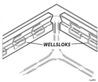
- This top-mounted built-in warmers is equipped with WELLSLOKS, uniquely designed turnout tabs which help secure the warmer top flange to the countertop.
- See the Installation Instructions, supplied with the particular appliance, for details.
C. DRAINS
- Suffix "D" units (e.g. HSW-6D) have drains for each pan. Each drain will require an individual drain valve.
PRECAUTIONS AND GENERAL INFORMATION
This appliance is intended for use in commercial establishments only.
This appliance is intended to hold pre-heated food for human consumption. No other use is recommended or authorized by the manufacturer or its agents.
Operators of this appliance must be familiar with the appliance use, limitations and associated restrictions. Operating instructions must be read and understood by all persons using or installing this appliance.
Cleanliness of this appliance is essential to good sanitation. Read and follow all included cleaning instructions and schedules to ensure the safety of the food product.
Disconnect this appliance from electrical power before performing any maintenance or servicing.
This appliance is not jet stream approved. Do not direct water jet or steam jet at this appliance, or at any control panel or wiring. Do not splash or pour water on, in or over any controls, control panel or wiring.
Exposed surfaces of this appliance can be hot to the touch and may cause burns.
Do not operate this appliance if the control panel is damaged. Call your Authorized Wells Service Agent for service.
The technical content of this manual, including any wiring diagrams, schematics, parts breakdown illustrations and/or adjustment procedures, is intended for use by qualified technical personnel.
Any procedure which requires the use of tools must be performed by a qualified technician.
This manual is considered to be a permanent part of the appliance. This manual and all supplied instructions, diagrams, schematics, parts breakdown illustrations, notices and labels must remain with the appliance if it is sold or moved to another location.
This appliance is made in the USA. Unless otherwise noted, this appliance has American sizes on all hardware.
WARNING: SHOCK HAZARD
All servicing requiring access to non-insulated electrical components must be performed by a factory authorized technician. DO NOT open any access panel which requires the use of tools. Failure to follow this warning can result in severe electrical shock.

CAUTION: RISK OF DAMAGE
DO NOT connect or energize this appliance until all installation instructions are read and followed. Damage to the appliance may result if these instructions are not followed.
CAUTION: HOT SURFACE
Exposed surfaces can be hot to the touch and may cause burns.
AGENCY LISTING INFORMATION
Refer to the product nameplate for the specific appliance for agency listings. In general:
This appliance conforms to NSF Standard 4 for sanitation only if installed in accordance with the supplied Installation Instructions.
UL Listed warmers are Listed under UL File E6070.
STD 4

E6070
INSTALLATION
NOTE: DO NOT discard the carton or other packing materials until you have inspected the appliance for hidden damage and tested it for proper operation.
Refer to SHIPPING DAMAGE CLAIM PROCEDURE on the inside front cover of this manual.

WARNING: RISK OF INJURY
Installation procedures must be performed by a qualified technician with full knowledge of all applicable electrical and plumbing codes. Failure can result in personal injury and property damage.

CAUTION FIRE HAZARD
Avoid storing flammable or combustible materials in, on or near the appliance.
IMPORTANT: For warmers installed in plastic counter tops, the counter material must be protected from the heat of the warmer in order to prevent discoloration and/or deterioration. Wellsloks are not suitable for this purpose. The installer should contact the manufacturer or distributor of the countertop material for specific instructions.
IMPORTANT: Wellslok Extension Kits must be used ONLY with UL Listed warmers approved for installation in wood counter tops. Refer to the Installation Instructions provided with the warmer.
UNPACKING & INSPECTION
Carefully remove the appliance from the carton. Remove all protective plastic film, packing materials and accessories from the Appliance before connecting electrical power or otherwise performing any installation procedure.
Carefully read all instructions in this manual and the Installation Instruction Sheet packed with the appliance before starting any installation.
Read and understand all labels and diagrams attached to the appliance.
Carefully account for all components and accessories before discarding packing materials. Store all accessories in a convenient place for later use.
INSTALLATION NOTES
- Installation and start up of built-in warmers MUST be performed by an authorized installation company.
- It is the responsibility of the installer to verify that this warmer installation is in compliance with the specifications listed in this manual and on the specification sheet provided.
-
It is the RESPONSIBILITY OF THE INSTALLER to check with the authority having jurisdiction, in order to verify that this warmer installation is in compliance with local code requirements.
-
Drain installation must meet all applicable local, state and federal plumbing codes and ordinances.
-
Refer to Installation Instructions included with the warmer for Underwriters Laboratories conditions of acceptability, electrical requirements and other installation concerns.
BUILT-IN WARMERS
- This is a GENERAL GUIDE. For specific cutout dimensions and other installation details, refer to the Installation Instructions supplied with the warmer.
- Cutout dimensions for warmer units and control panels are listed on the Installation Instructions provided with the warmer.
- Verify style of control panel (e.g square, rectangular) before making cutout.
NOTE: Cutout dimensions are different for square and rectangular control panels, for UL LISTED units and UL Recognized units, and for wood and metal counters. Verify the dimensions are correct for the installation before making the cutout.
INSTALLATION
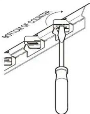
- For "top-mounted" warmers (i.e. warmers mounted from above the counter top):
a. Verify that provided sealants are applied to the underside of the warmer top flange prior to setting the unit into the cutout.
b. After installation, verify that the tabs on the Wellsloks are turned out to lock the warmer into the counter
c. Apply a thin bead of food-grade silicone sealant around the flange to seal it to the counter.
d. Wellslok extension kits are available for installing warmers in counter tops where the standard Wellslok would not normally reach. The extension kit will adapt to counter tops up to 1 ^3/4 " thick.
ELECTRICAL INSTALLATION
- Refer to the product nameplate. Verify the electrical service power. Voltage and phase must match the nameplate specifications. Wiring the warmer to the wrong voltage can severely damage the unit or cause noticeably decreased performance.
- Available electrical service amperage must meet or exceed the specifications listed on the specification sheet provided with the warmer.
- Warmer and control unit must be connected to an appropriate building ground. Ground connection will be marked "GND" or "1".
NOTE: Wire gauge, insulation type and temperature rating, as well as type, size and construction of conduit, must meet or exceed applicable specifications of local codes and of the National Electrical Code.
PLUMBING INSTALLATION
For use in the State of Massachusetts, this appliance must be installed in compliance with Massachusetts Fuel Gas and Plumbing Code CMR 248.
- IMPORTANT: All plumbing installations must be performed by a qualified plumber.
- For units equipped with a DRAIN LINE: Some jurisdictions may require an approved air gap or other back-flow prevention device in the drain. It is the responsibility of the plumber to determine such requirement, to provide and properly install the required device.
NOTE: Damage caused by leaks due to improper installation is NOT covered by warranty.

CAUTION: SHOCK HAZARD
The ground lug of this appliance must be connected to a suitable building ground.
IMPORTANT:
Contact a licensed electrician to install and connect electrical power to the appliance.
IMPORTANT:
Damage due to being connected to the wrong voltage or phase is NOT covered by warranty.
IMPORTANT: Electrical installation other than as specified on the specification sheet will void the UL listing, and may void the warranty.
NOTE: Plumb connections must be made in compliance with all Federal, State and Local Plumbing Codes and Ordinances.
OPERATION

CAUTION: HOT SURFACE
Exposed surfaces can be hot to the touch and may cause burns.

CAUTION: SHOCK HAZARD
DO NOT splash or pour water onto control panel or wiring.
Always use an inset. DO NOT place food directly into the warmer.
Always pour hot water into the warmer before it is preheated. DO NOT pour water into a dry, heated warmer. This may damage the unit.
DO NOT put ice into a warmer pan. This will cause condensation on the inside of the warmer. Damage caused by condensation is NOT covered by warranty.
Stir thick food items frequently to keep food heated uniformly.
Keep insets covered to maintain food quality and temperature.
WET OR DRY OPERATION for WARMERS
- Carefully read the description of the warmer operation on the specification sheet.
-
a. Most warmers are designed for WET OR DRY operation.
b. Warmers may be used wet, or may be used dry. However warmers may NOT be used wet-to-dry or dry-to-wet unless they have been allowed to cool to room temperature between the change in wet or dry operation.
c. W ells Manufacturing recommends operating WET for consistent food heating.
d. If your wet-operation warmer is allowed to run dry , turn it OFF and allow to cool to room temperature before adding water. -
If the warmer is to be used for WET operation, add approximately 1" of hot tap water before turning the warmer on. Use of hot water will allow a faster preheat.
a. Check the water level frequently and add hot water as necessary to prevent the warmer from running dry. Do not add water to the warmer if it has run dry.
b. If your wet-operation warmer is allowed to run dry , turn it OFF and allow to cool to room temperature before adding water.
- Damage caused by allowing a wet-operation warmer to run dry, is NOT covered by warranty. Damage caused by adding water to a dry warmer when hot is NOT covered by warranty.
PRE-HEATING THE WARMER
- Place desired pan(s) or inset(s) with appropriate adapter top on warmer.
- T urn temperature control to highest temperature setting.
- Allow warmer to preheat for approximately 30 minutes, then set the control for the desired temperature. Be sure to keep the warmer covered during preheat and operation.
OPERATION
- Always use an inset. DO NOT place food directly into the warmer.
- Check water level in wet-operation warmer frequently during use. Running warmers dry will lower the temperature of the food in the insert pan, and may damage the warmer.
- Alternating between wet and dry operation in any individual warmer is NOT recommended.
- DO NOT use metal tools, steel wool, or caustic or abrasive cleanser to clean warmer pan.
MAINTENANCE INSTRUCTIONS
CARE OF STAINLESS STEEL
Stainless steel is a marvelous material: strong, lustrous and low maintenance. With a minimum of care, it will normally retain its beauty and durability for the life of the equipment. In some applications, however, special care is required in order to maintain stainless steel's special properties.
External components, such as cabinets and control panels, are finished with a grain pattern. This pleasing finish is best maintained by cleaning with a non-abrasive cleanser applied with a soft cloth. Rub only in the direction of the grain. In the absence of visible grain, rub only along the longest axis of the appliance.
Restore stainless steel's luster by applying a polish specifically made for stainless steel. Spray on, wipe off with a soft cloth, rubbing in the direction of the grain.
Never use metal implements, wire brushes, abrasive scratch pads or steel wool to clean stainless steel.
Warmer pans, insets and other vessels are subject to a harsher environment. Wells Manufacturing uses an very high quality stainless steel (#304DDQ) for our food warmer pans. Even the highest quality stainless steel, however, is mostly iron, and will rust, pit and corrode under the following conditions:
- Poor Water Quality: Hard water (water with a high content of dissolved minerals) will leave mineral deposits when allowed to dry. Calcium (lime) can buildup on heated surfaces, even under water. If left unattended, hard water spots and lime buildup can lead to rusting, corrosion and pitting.
- Contact with Chlorides: Chlorides (specific compounds of chlorine) are found in food, table salt and many cleansers. Chlorides can attack the surface of stainless steel, resulting in corrosion and pitting.
Keep your stainless steel warmers clean and free from calcium buildup.
Use alkaline, alkaline chlorinated or non-chloride cleanser.
Use citric acid-based cleaners to remove calcium deposits.
For additional information, please read the NAFEM Stainless Steel Equipment and Cleaning Guide. Contact NAFEM at :
North American Association of Food Equipment Manufacturers
401 N. Michigan Avenue
Chicago, Illinois 60611-4267
(312) 644-6610
CLEANING INSTRUCTIONS
CAUTION: SHOCK HAZARD
Do NOT splash or pour water into or over any control panel or wiring.
CAUTION: SHOCK HAZARD
Disconnect warmer from electric power before cleaning
CAUTION: BURN HAZARD
Allow warmer to cool completely before cleaning.
DAILY CLEANING INSTRUCTIONS
PREPARATIONS: Turn control knob(s) to OFF. Allow warmer to cool before proceeding.
Remove any insets, pans and/or adapter tops. Drain or remove water from well if used for wet operation.
FREQUENCY: Minimum - daily.
TOOLS: Mild Detergent
Solution: 10 Parts Warm Water to 4 Parts Vinegar
Plastic Scouring Pad
Clean Cloth or Sponge
Food-Grade Silicone Sealant
- Wipe entire unit down using a clean cloth or sponge and mild detergent.
- Use a plastic scouring pad to remove any hardened food particles or mineral deposits. IMPORTANT: Do NOT use steel wool for cleaning.
- Rinse warmer thoroughly with a vinegar and water solution to neutralize all detergent cleanser residue.
- Inspect warmer flange-to-counter seal. Reseal with food-grade silicone sealant if necessary. Failure to do so may allow grease and water to leak into insulation and heating element, causing a potential fire and/or electric shock hazard.
- Inspect warmer tank for damage. Damage to the outer body may allow grease and water to leak into insulation and heating element, causing a potential fire and/or electric shock hazard. Contact your Authorized Wells Service Agency to inspect warmer if water or grease contamination is suspected.
- Close drain valve. Add proper amount of warm water. Turn control knob(s) ON and check for proper operation.
CLEANING INSTRUCTIONS
WEEKLY CLEANING INSTRUCTIONS
PREPARATIONS: Remove any insets, pans and/or adapter tops. Drain or remove water from well if used for wet operation.
FREQUENCY: Weekly, or whenever lime or scale is seen accumulating on the sides of the warmer pans.
TOOLS: Commercial Delime Cleaner Plastic Scouring Pad Clean Cloth or Sponge

CAUTION: CHEMICAL BURN HAZARD
Deilimg chemicals may be caustic. Wear appropriate personal protective equipment. Follow cleaner manufacturer's instructions for safest use.
- Add water to pans until water is at normal operating level (1" - 1 1/2" deep) or covers accumulated scale.
- Heat water to maximum temperature (190°F or higher).
- Pour contents of one package of commercial delime cleaner into each warmer pan. Stir to dissolve cleaner. Turn heat control OFF. Cover pans.
- Allow solution to soak at least one hour, or overnight for heavy scale buildup.
- Drain hot water from pans. Scrub with a plastic scouring pad. Rinse thoroughly with hot water, then dry.
- Refill pans with hot tap water and resume operation.
- Heavy scale buildup may require additional treatments.
TROUBLESHOOTING SUGGESTIONS
TROUBLESHOOTING
| SYMPTOM POSSIBLE CAUSE SUGGESTED REMEDY | ||
| No power to warmer Circuit breaker off or tripped Reset circuit breaker | ||
| Warmer will not heat Temperature control not set Set control to desired temperature | ||
| Warmer trips circuit breaker | Wet insulation | Verify flange-to counter seal is sound, or reseal with food-grade silicone sealant |
| Pan leaking or other internal damage | Contact your Authorized Wells Service Agency for repairs | |
| Internal damage | Contact your Authorized Wells Service Agency for repairs | |
| Warmer slow to heat | Mineral deposits on pan acting as a insulator | Clean pan(s) with delime cleaner |
| Wired to wrong voltage | Verify supply voltage - must match voltage on warmer nameplate | |
| Drain-equipped unit will not hold water | Drain valve not fully closed Check drain valve for debris and close fully | |
| Drain valve damaged or pan(s) leaking | Contact your Authorized Wells Service Agency for repairs | |
There are no user-serviceable components in this appliance.
In all instances of damage or malfunction, contact your Authorized Wells Service Agency for repairs.
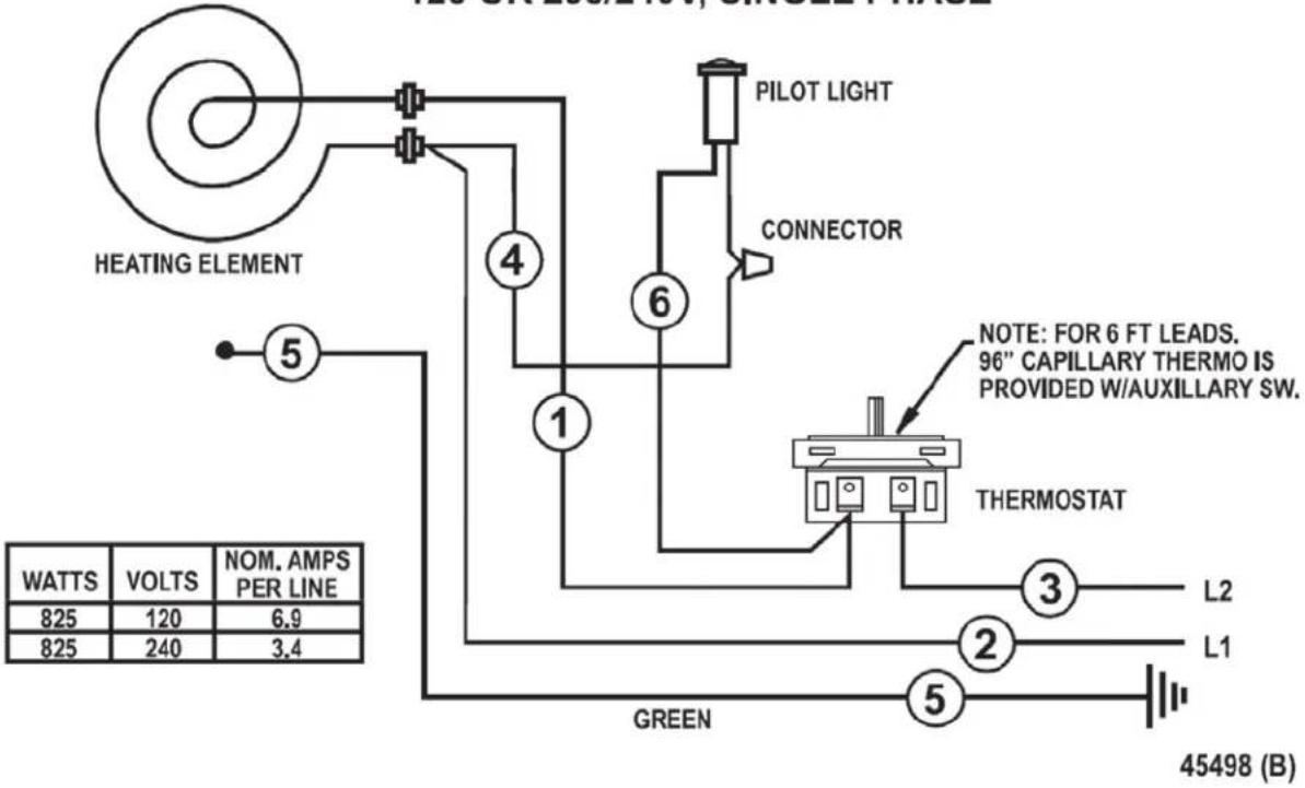
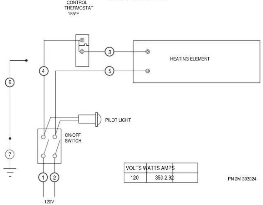
WIRING DIAGRAM
WIRING DIAGRAM FOR HSW-WARMERS
120 OR 208/240V, SINGLE PHASE
WIRING DIAGRAM TSW-6UL
120 VOLTS SINGLE PHASE
EXPLODED VIEW & PARTS LIST
HSW-6 and HSW-6D
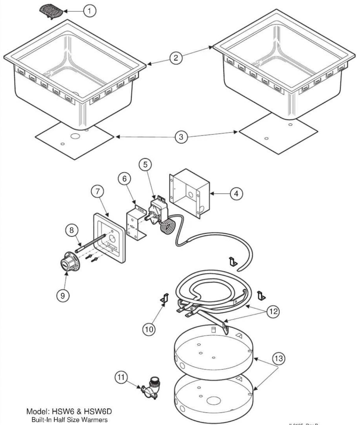
M011A 2M-308013 Owners Manual for Built-In Half Size Warmers
EXPLODED VIEW & PARTS LIST
| Model: HSW6 Series Half Size Warmers | ||||
| Fig No. Part Number Description Qty Application | ||||
| 1 5P-2 | 1709 SPRING SCREEN DRAIN WARMER 1 HSW6D-120V, HSW6D | |||
| 2 | P2-41854 PAN & TOP ASSY HSW-6 | 1 | HSW6-120V | |
| P2-43422 TOP & POT ASSY HSW6D | HSW6D-120V, HSW6D6, HSW6D6-120 | |||
| 3 | P2-40743 PLATE HEAT TRANSFER HSW-6 | 1 | HSW6-120V, HSW66-120V | |
| P2-43427 PLATE HEAT TRANSFER HSW-6 | HSW6D-120V, HSW6D, HSW6D6, HSW6D6-120 | |||
| 4 P2-Z | 16805 BOX, CONTROL 1 HSW6-120V | |||
| 5 | WS-60282 THERMO CTRL SS8T ROHS | 1 | HSW6-120V, HSW6D-120V | |
| 2T-46551 THERMO CTRL 96IN CAP RO | HSW66-120V, HSW6D6, HSW6D6-120 | |||
| 6 P2-4 | 0843 BRKT MTG THERMO INFINITE 1 HSW6-120V | |||
| 7 I7-Z | 2221 PANEL, FRONT 1 HSW6-120V | |||
| 8 | 2J-35687 | LIGHT SIGNAL GLO DOT W#8 | 1 | HSW6-120V, HSW6D-120V |
| 9 | 2R-40498 | KNOB ASSY MOD 100DT HI/LO | 1 | HSW6-120V |
| 10 | D8-306439 | CLAMP BULB SW10 ROHS | 3 | HSW6-120V |
| 11 | 2K-34136X FTG FLEX CON 90 X 1/2 MOD | 1 | HSW6-120V | |
| 2K-34136X FTG FLEX CON 90 X 1/2 MOD | HSW6-120V | |||
| 12 | WS-506272 | ELEM 120V 825W SS-8T 10T | 1 | HSW6-120V, HSW6D-120V, HSW66-120V |
| WS-506273 | ELEM 240V 825W SS-8T 10T | HSW6D, HSW6D6 | ||
| 13 | 2D-31878 | COVER ELEM SS8D SS10D RO | 1 | ALL |
| NI | 2K-31040 | BUSHING HEYCO 7/8 OD | 1 | HSW6-120V |
| NI | 2M-40740-1 | INSTALL INSTR HSW-6 | 1 | HSW6-120V |
| NI | 2M-45498 | DIA WIR SS WARMER 120,208 | 1 | HSW6-120V |
EXPLODED VIEW & PARTS LIST
TSW6ULD
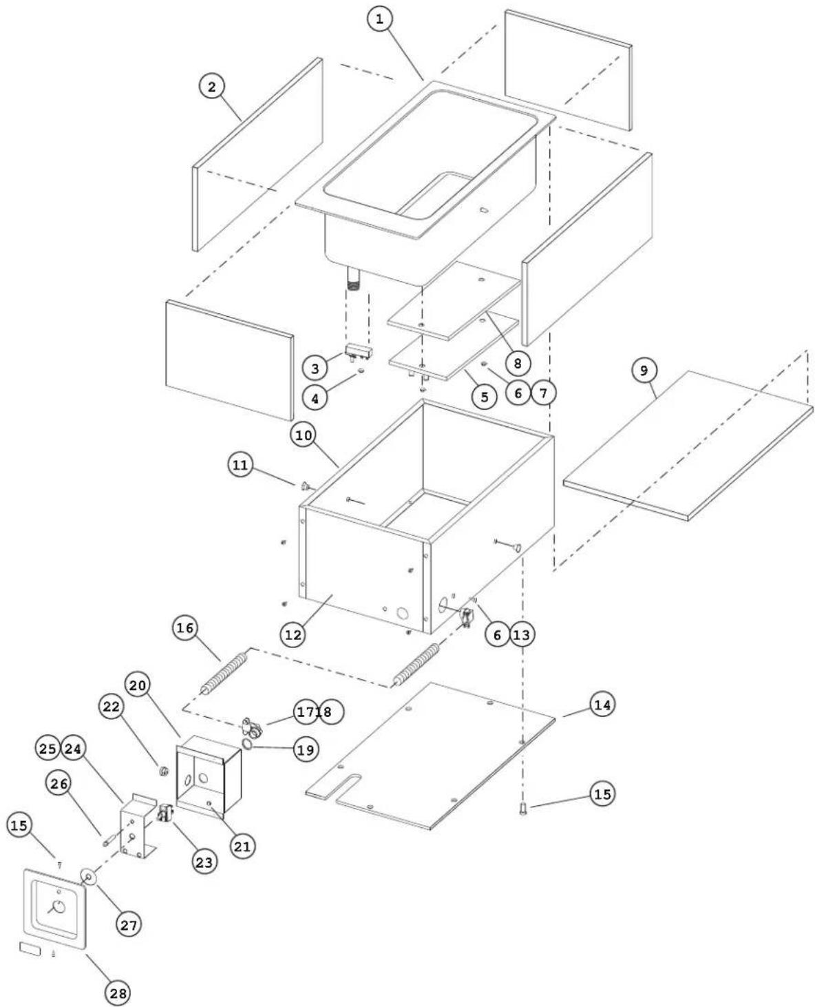
Model: TSW6D
Built-In Third Size Warmer w/ Fixed Thermostat
IL2264, Rev -
EXPLODED VIEW & PARTS LIST
Model: TSW6ULD Third Size Warmer
| Fig No Part No Description Qty | |||
| 1 P2-303017 PAN ASSY TSW-6ULD 1 | |||
| 2 2H-40686 INSUL SIDES HSW-6 3 | |||
| 3 2T-40528 THERMO CTRL HMP 1 | |||
| 4 2C-33961 NUT 6-32 HEX MACH SCR KEP 2 | |||
| 5 2N-303022UL ELEM TSW-6UL 120V 1 | |||
| 6 2C-31053 NUT 8-32 KEPS MS NICKEL 4 | |||
| 7 2C-32243 WASHER FLAT ZI #12 SAE 2 | |||
| 8 P2-303020 PLATE HEAT TRANSFER TSW-6 1 | |||
| 9 2H-40685 INSUL BOT H$W-6 1 | |||
| 10 | P2-303018 | SHROUD WRAP TSW-6UL ROHS | 1 |
| 11 | 2C-44144 WELD NUT 8-32 W/FLANGE NI 2 | ||
| 12 | P2-303019 | SHROUD FRONT TSW-6UL ROH | 1 |
| 13 | 2C-31715 SCREW 8-32X5/16 PH RD HD 1 | ||
| 14 | P2-303021 COVER BOTTOM TSW-6UL ROHS 1 | ||
| 15 | 2C-33935 SCREW 6ABX5/16 PH PAN SMS 10 | ||
| 16 | P2-33995 | CONDUIT FLEX 3/8X37 1/4" | 1 |
| 17 | 2K-33996X | FTG FLEX CONDUIT 90X3/8 | 2 |
| 18 | 2I-Z12311 | GASKET-FIBER WASHER | 2 |
| 19 | 2P-35985 | CAPLUG 7/8 B P F | 1 |
| 20 | P2-31033 | BOX CONTROL MOD100T ROHS | 1 |
| 21 | 2C-35736 NUT 8-32 HEX KEPS MS GREE 1 | ||
| 22 | 2K-31040 | BUSHING HEYCO 7/8 OD | 1 |
| 23 | 2E-30330 | SWITCH ON OFF TOGGLE 20A | 1 |
| 24 | I7-302462 | BRKT MNTG SWITCH H006UL | 1 |
| 26 | 2J-35687 | LIGHT SIGNAL GLO DOT W#8 | 1 |
| 27 | I7-302461 | COVER SWITCH HOLE H006UL | 1 |
| 28 | I7-Z12221 | PANEL, FRONT | 1 |
| NI | 2M-303024 | DIA WIR TSW6UL 120V | 1 |
| NI | 2E-303025A | WIRE SET TSW6ULD 3FT LEAD | 1 |
NOTES
PARTS & SERVICE
| DESCRIPTION | PART NO. | IMPORTANT: Use only factory authorized service parts and replacement filters. |
| ACCESSORIES | ||
| DRAIN SCREEN | P2-31869 | For factory authorized service, or to order factory authorized replacement parts, contact your Wells authorized |
| OPTIONAL 72” WIRING, thermostatically controlledwarmers ** | ||
| ** contact factory customer service for availability | ||
service, or to order factory authorized replacement parts, contact your Wells authorized service agency, or call:
Wells Manufacturing 10 Sunnen Dr., St. Louis MO 63143 USA
Service Dept. phone: (314) 678-6314 fax: (314) 781-2714
Service Parts Department can supply you with the name and telephone number of the WELLS AUTHORIZED SERVICE AGENCY nearest you.
CUSTOMER SERVICE DATA
please have this information available if calling for service
| RESTAURANT | LOCATION |
| INSTALLATION DATE | TECHNICIAN |
| SERVICE COMPANY | |
| ADDRESS | STATE ZIP |
| TELEPHONE NUMBER (____) - | |
| EQUIPMENT MODEL NO. | |
| EQUIPMENT SERIAL NO. | |
VOLTAGE:(checkone)

120



Wells Bloomfield proudly supports CFESA Commercial Food Equipment Service Association
SERVICE TRAINING - QUALITY SERVICE

CUSTOMER SATISFACTION

WELLS MANUFACTURING
10 Sunnen Dr., St. Louis, MO 63143
telephone: 314-678-6314
fax: 314-781-2714
www.wellsbloomfield.com
- IMPORTANT: DO NOT DISCARD THIS MANUAL
- LIMITED WARRANTY STATEMENT
- SERVICE POLICY AND PROCEDURE GUIDE and ADDITIONAL WARRANTY EXCLUSIONS
- SHIPPING DAMAGE CLAIM PROCEDURE
- IF SHIPMENT ARRIVES DAMAGED:
- TABLE OF CONTENTS
- INTRODUCTION
- SPECIFICATIONS
- FEATURES & OPERATING CONTROLS
- THERMOSTAT
- MOUNTING
- DRAINS
- PRECAUTIONS AND GENERAL INFORMATION
- WARNING: SHOCK HAZARD
- CAUTION: RISK OF DAMAGE
- CAUTION: HOT SURFACE
- AGENCY LISTING INFORMATION
- INSTALLATION
- WARNING: RISK OF INJURY
- CAUTION FIRE HAZARD
- UNPACKING & INSPECTION
- INSTALLATION NOTES
- BUILT-IN WARMERS
- ELECTRICAL INSTALLATION
- PLUMBING INSTALLATION
- CAUTION: SHOCK HAZARD
- IMPORTANT:
- OPERATION
- WET OR DRY OPERATION for WARMERS
- PRE-HEATING THE WARMER
- MAINTENANCE INSTRUCTIONS
- CARE OF STAINLESS STEEL
- Never use metal implements, wire brushes, abrasive scratch pads or steel wool to clean stainless steel.
- CLEANING INSTRUCTIONS
- CAUTION: BURN HAZARD
- DAILY CLEANING INSTRUCTIONS
- WEEKLY CLEANING INSTRUCTIONS
- TROUBLESHOOTING SUGGESTIONS
- WIRING DIAGRAM
- EXPLODED VIEW & PARTS LIST
- NOTES
Brand : Wells
Model : HSW6D
Category : Food Warmer