
RoboTRAK - Security Camera Vaddio - Free user manual and instructions
Find the device manual for free RoboTRAK Vaddio in PDF.


| Product Type | Security Camera |
| Model | RoboTRAK |
| Brand | Vaddio |
| Category | PTZ Security Camera |
| Image Sensor | 1/2.8-inch CMOS |
| Resolution | 1920 x 1080 (Full HD) |
| Frame Rate | Up to 60 fps |
| Optical Zoom | 12x |
| Pan Range | 360° endless |
| Tilt Range | -20° to +90° |
| Preset Positions | Up to 100 |
| Auto Tracking | Yes (with RoboTRAK technology) |
| Video Output | HDMI, SDI, IP (H.264/H.265) |
| Power Supply | PoE+ (IEEE 802.3at) or 24V AC |
| Power Consumption | Typical 20W, max 30W |
| Dimensions (H x W x D) | 28.5 cm x 18.0 cm x 18.0 cm |
| Weight | 2.3 kg |
| Mounting | Ceiling or table mount (via included bracket) |
| Compliance | CE, FCC, RoHS |
| Operating Temperature | 0°C to 40°C |
| Storage Temperature | -20°C to 60°C |
| Humidity | 20% to 80% (non-condensing) |
| Cleaning Instructions | Wipe with dry cloth; use mild detergent if needed. Do not immerse in water. |
| Security Features | Password protection, HTTPS, 802.1X authentication |
| Repairability | Replaceable parts: lens module, motor assembly, power supply. Contact Vaddio support for spare parts. |
Frequently Asked Questions - RoboTRAK Vaddio
User questions about RoboTRAK Vaddio
0 question about this device. Answer the ones you know or ask your own.
Ask a new question about this device
Download the instructions for your Security Camera in PDF format for free! Find your manual RoboTRAK - Vaddio and take your electronic device back in hand. On this page are published all the documents necessary for the use of your device. RoboTRAK by Vaddio.
USER MANUAL RoboTRAK Vaddio
Drop-Down Mount Accessory for RoboTRAK™
UNPACKING:
Carefully remove the product and all of the parts from the packaging. Unpack and identify the following parts (cameras not included):
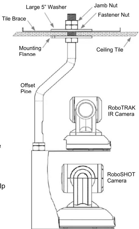
① One (1) 1-14 Hex Nut (jamb nut)1.5" across by .375" Tall
② One (1) Offset Pipe with 1-14 Threads
③ One (1) Mounting Flange (5" diameter)
④ One (1) Tile Support Brace
⑤ One (1) Large 5" Washer
⑥ Two (2) 1-14 Hex Nut, 1.5" across x .547" Tall (one used as fastener and the other as a top jamb nut)
(Cameras are not included)
Step 1: For suspended ceiling installations, mark a position in the center of a ceiling tile where the ceiling mount is to be placed. The hole must be positioned at the center of the ceiling tile lengthwise for 2' x 4' ceiling tiles to line up with the tile support brace. Use the tile support brace as a template. The tile support brace is meant to span the tile and distribute the weight into the grid.
For drywall ceiling installations, mark a position in the ceiling while making sure that there are no obstructions (structural supports, electrical, etc.) in the area above the mount.
Step 2: Drill or cut a 1" (25.4mm) diameter hole in the tile or drywall at the point where you marked the hole. For suspended ceiling installations, place the support brace on the top of the ceiling tile and align the hole with the tile support brace. There are six holes drilled in the support brace for attaching to the building structure where regional codes require this additional support.
For drywall ceiling installations, place the Mounting Flange over the 1" hole, and mark the four locations in the flange to install appropriate hardware (wall anchors) for mounting the flange to the ceiling.

Step 3: Thread the 1.5" x .375" Jam Nut onto the bottom of the pipe (the side with the shorter threads), then thread the Camera Platform all the way onto the pipe. Back the Camera Platform off the pipe (one rotation or less) until the back of the Camera Platform aligns with the cable pass-thru. Carefully tighten the 1.5" x .375" Jam Nut down onto the threaded nut of the Camera Platform.
Step 4: Thread the painted 5" flange onto the other end of the pipe.
Step 5: For suspended ceiling installations, slide the pipe with 5" flange end through the hole in the ceiling tile. From one tile over, place the 5" washer onto the threaded pipe, and screw the first 1.5" x 5.5" hex nut onto the pipe thread and tighten the hex nut down, then thread the second hex nut (jam nut) onto the top of the pipe and tighten it. Carefully feed the Cat-5 cabling through the pipe and the cable pass-thru at the back of the camera mount. There are six (6) mounting points on the Tile Support Brace to allow the integrator to tie the assembly to the structure for safety in seismic prone areas.
For drywall ceiling installations, once the appropriate mounting hardware for the flange is installed, carefully pull the Cat-5 cabling through the 1" hole in your drywall ceiling. Thread the cabling through the pipe, and pull it through the cable pass thru at the back of the camera platform. Place the flange on the ceiling and tighten the screws down onto the mounting hardware.
Step 6: Place your camera onto the mount and secure it to the camera platform using the supplied black screw(s). Connect the Cat. 5 cabling to the back of the camera and carefully feed excess Cat. 5 cabling back into the ceiling. Use the 14 " - 20 x .375: screws for the RoboSHOT cameras.
INSTALLING THE MOUNT AND CAMERA:
The Drop-Down Series of camera mounts can be mounted to either 2 x 2' or 2' x 4' ceiling tiles, or a drywall ceiling. When locating the camera, consider viewing angles, lighting conditions, line of site obstructions and check for vibration where the camera is to be mounted. Pick a location to optimize the performance of the camera.
The integrator is responsible for following building codes, determining the suitability of the suspended or drywall ceiling to carry the load of the camera and mount, as well as making sure that the camera is secured to the camera platform properly.
To the right, a diagram is provided for your information and visualization pleasure. The mounting system should go together as depicted.
INTENDED USE:
These products were designed, built and tested for use indoors and to support the weight, size and shape of the prescribed products only. Using these mounts for any other devices could damage that device and/or create potentially unsafe operating conditions.
SAVE THESE INSTRUCTIONS: The information contained in this manual will help you install and operate your product. If these instructions are misplaced, Vaddio keeps copies of Specifications, Installation and User Guides and most pertinent product drawings for the Vaddio product line on the Vaddio website. These documents can be downloaded from www.vaddio.com free of charge.
HARDWARE WARRANTY:
Please see the Vaddio website at support.vaddio.com for the Vaddio Statement of Warranty for all Vaddio Products. The Statement of Warranty covers the policies and procedures of the Hardware Warranty, Exclusions, Customer Service, Technical Support, Return Material Authorizations (RMA), Voided Warranty, Shipping and Handling and Products Not Under Warranty. The Vaddio Warranty Statement supersedes all other published warranty statements in content and coverages. Vaddio Technical Support can be contacted through the Vaddio website or through e-mail support at support.vaddio.com.
SPECIFIC EXCLUSIONS:
The Drop-Down Offset Mount for the RoboTRAK system is optional. The RoboTRAK system is not included. The double decker mount is included with the RoboTRAK system as a wall mount and is not included with the Drop-Down Offset Mount. If there is any questions regarding what's included please look at the manuals or contact Vaddio Tech Support.
Double Decker RoboTrak Mount (Ships with RoboTRAK System)

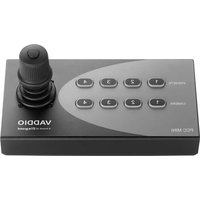
Brand : Vaddio
Model : RoboTRAK
Category : Security Camera