
EasyIP 20 - Security Camera Vaddio - Free user manual and instructions
Find the device manual for free EasyIP 20 Vaddio in PDF.


| Type | AV-over-IP PTZ Security Camera |
| Image Sensor | 8.5 Megapixel effective, native 1080p/60 full HD |
| Optical Zoom | 20x |
| Horizontal Field of View | 70.2° |
| Pan / Tilt Speed | Up to 120° per second |
| Video Resolution | Up to 1080p/60 |
| Video Output | HDMI (local), AV-over-IP |
| Network Connectivity | RJ-45 PoE+ (10/100) |
| RS-232 Control | Yes (modified VISCA protocol) |
| IR Remote | Included (Vaddio IR Remote Commander) |
| Power Supply | PoE+ (IEEE 802.3at) |
| Mount | Thin Profile Wall Mount included |
| Status Indicator | Multi-colored LED (blue=active, purple=standby, yellow=firmware update, blinking red=video mute) |
| Pairing | Pairs with EasyIP Decoder or EasyIP Mixer (up to two host devices) |
| Compatible Host Devices | EasyIP Decoder, EasyIP Mixer |
| Included Accessories | Camera, IR remote, wall mount with hardware, 10 ft Cat-5e cable, Quick-Start Guide |
| Color Options | Black (999-30230-000) or White (999-30230-000W) |
| Warranty | Standard Vaddio warranty (contact support for details) |
Frequently Asked Questions - EasyIP 20 Vaddio
User questions about EasyIP 20 Vaddio
0 question about this device. Answer the ones you know or ask your own.
Ask a new question about this device
Download the instructions for your Security Camera in PDF format for free! Find your manual EasyIP 20 - Vaddio and take your electronic device back in hand. On this page are published all the documents necessary for the use of your device. EasyIP 20 by Vaddio.
USER MANUAL EasyIP 20 Vaddio
natural_image
Product photo of vaddi audio recording devices including a video player, a Easy5+ Decoder, and a Vaddi-branded device (no visible text or symbols on main components)Installation Guide for
EasyIP Systems
Featuring the EasyIP Decoder, EasyIP Mixer, and EasyIP Cameras
Document 411-0041-39 Rev D July 2020
Contents
Overview 1.
What's in this Guide.2....
The EasyIP Ecosystem.2....
EasyIP Decoder.2
EasyIP Mixer.2
EasyIP Cameras.2
EasyIP Switch 3
EasyIP Decoder Features 3.
EasyIP Mixer Features.3....
EasyIP 10 Camera Features.3....
EasyIP 20 Camera Features 4
Unpacking the EasyIP System Components.... 5
EasyIP Decoder AV-over-IP Switching USB Endpoint 5
EasyIP Mixer AV Switcher 5
EasyIP 10 AV-over-IP PTZ Camera....6
EasyIP 20 AV-over-IP PTZ Camera....7
A Quick Look at the EasyIP Family 8
EasyIP Decoder 8
Front View 8
Back View 8
EasyIP Mixer 9
Front View 9
Back View 9
EasyIP 10 Camera.... 10
Front View....10
Back View....10
EasyIP 20 Camera....11
Front View.... 11
Back View 11
Installation 12
Don't Void Your Warranty! 12
Before You Start 12
Before Installing Cameras.... 13
Cabling Notes.... 13
RS-232 Serial Communication Settings and Port Pin-outs 14
EasyIP Mixer 14
EasyIP 20 Camera....15
Basic Connections - EasyIP Decoder 16
Basic Connections - EasyIP Mixer.... 17
Basic Connections – EasyIP Mixer with HDMI Input from EasyIP 20 Camera .....18
Installation Guide for EasyIP Systems
Installing the Wall Mount for the Camera 19....
About Ceiling-Mounted Cameras 19.
Installing the Camera 20
Powering Up the EasyIP System 21.
Next Steps 21
Operation, Storage, and Care 21
Compliance and Conformity Statements 22.
FCC Part 15 Compliance 22
ICES-003 Compliance 22
European Compliance 23
Photo Credits 24
Index 25
Overview
This guide discusses the following products:
■ EasyIP Decoder AV-over-IP switching USB endpoint, 999-60210-000 (worldwide)

■ EasyIP Mixer AV switcher, 999-60320-000 (worldwide)

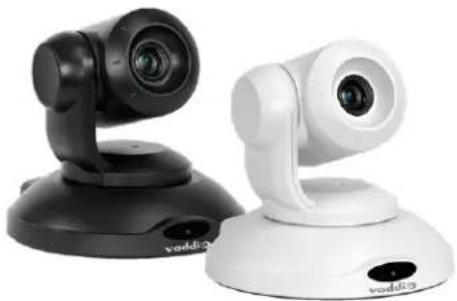
■ EasyIP 10 AV-over-IP PTZ camera, 999-30200-000 (black, worldwide) EasyIP 10 AV-over-IP PTZ camera, 999-30200-000W (white, worldwide)
natural_image
Two white and black VDDI 2 camera devices on a stand, no visible text or symbols on the device body.■ EasyIP 20 AV-over-IP PTZ camera, 999-30230-000 (black, worldwide) EasyIP 20 AV-over-IP PTZ camera, 999-30230-000W (white, worldwide)

natural_image
Exterior view of a modern automated camera with dual lenses and display units (no visible text or symbols)What's in this Guide
This guide covers:
■ Unpacking the system
■ Tips for a successful installation
■ Instructions for installing the camera mount
■ Information on connecting the system components
■ Information on mounting the camera
■ System power-on
Complete product information for the EasyIP product family is available in the Complete Manual for
EasyIP Systems.
Note
If you are responsible for configuring the equipment after installing it, you will need the Manual. It includes the information from this guide, plus information on system administration, operation, and troubleshooting.
The EasyIP Ecosystem
Vaddio® EasyIP products are designed to be used together, and have limited or no compatibility with other types of products.
■ EasyIP cameras deliver video in Vaddio's proprietary EasyIP format.
- An EasyIP host device (EasyIP Decoder or EasyIP Mixer) is required to convert the cameras' output signal to an IP and/or USB stream.
■ Only paired EasyIP cameras can be controlled by the EasyIP host device.
■ EasyIP host devices automatically detect EasyIP cameras on its own subnet.
■ Cameras are not required to be on the same subnet as the device that manages them.
■ EasyIP products require PoE+ power. Typically the EasyIP system is powered by a PoE+ switch.
EasyIP Decoder
The decoder is the central component of a basic EasyIP installation. Its functions include
■ Video – pair with up to four cameras at a time, control the active camera via web interface, and decode the camera's AV-over-IP signal.
■ Audio – connect two EasyMic microphones (CeilingMIC or TableMIC) and a speaker.
- USB streaming – configure for UVC-compliant or client-custom USB streaming for conferencing applications.
EasyIP Mixer
The mixer is the central component of a full-featured EasyIP pro AV room solution. Its functions include
■ Video – pair with up to four cameras at a time, control the active camera via web interface, and decode the camera's AV-over-IP signal.
■ Audio – two balanced audio inputs and outputs; pair with audio products on your network – including up to four EasyIP microphones. Built-in audio mixer.
- USB streaming – configure for UVC-compliant or client-custom USB streaming for conferencing applications.
EasyIP Cameras
EasyIP cameras may be installed anywhere on the network. They require only a PoE+ power connection.
An EasyIP Decoder or EasyIP Mixer is needed as a host device to decode the AV-over-IP signal.
Each camera may be paired to two host devices.
EasyIP Switch
A PoE+ switch simplifies installation, eliminating the need for PoE+ power injectors and placing all the connected products on the same subnet.
EasyIP Decoder Features
■ Uncompressed USB 3.0 streaming
■ Streaming video resolutions up to 1080p/60
■ Full-duplex audio streaming
■ Audio inputs for two Vaddio EasyMic microphones
■ HDMI video output for local display
■ Universal Video Class (UVC) and Universal Audio Class (UAC) drivers supported in ^® , Windows macOS ^® , and Linux operating systems, compatible with most UC conferencing applications
■ Integration-ready Telnet control
■ Pairs with up to four EasyIP 10 cameras on your network to provide control and manage streaming
■ Enterprise-class IT administrative capabilities with full web controls for remote management
EasyIP Mixer Features
■ Uncompressed USB 3.0 streaming
■ Streaming video resolutions up to 1080p/60
■ Full-duplex audio streaming
■ Line-level inputs for two microphones
■ Line-level outputs for two speakers
■ Audio mixer and video switcher
■ Support for microphones and speakers with Dant Connectivity
■ HDMI video output for local display
■ Universal Video Class (UVC) and Universal Audio Class (UAC) drivers supported in®, Windows macOS®, and Linux operating systems, compatible with most UC conferencing applications
■ Integration-ready Telnet control
■ Pairs with up to four EasyIP 10 cameras on your network to provide control and manage streaming
■ Enterprise-class IT administrative capabilities with full web controls for remote management
EasyIP 10 Camera Features
■ 2.14 Megapixel effective, native 1080p/60 full HD image sensor
■ 10x optical zoom, horizontal field of view of 67°
■ Resolutions up to 1080p/60
■ Precise pan and tilt movements at up to 90° per second
■ Integration-ready Telnet control
- Pairs with an EasyIP Decoder or EasyIP Mixer, which provides video and audio connectivity and manages streaming; each camera may be paired to two host devices.
- Just one cable – the EasyIP connection to a PoE switch
■ Enterprise-class IT administrative capabilities with full web controls for remote management
EasyIP 20 Camera Features
■ 8.5 Megapixel effective, native 1080p/60 full HD image sensor
■ 20x optical zoom, horizontal field of view of 70.2°
■ Resolutions up to 1080p/60
■ Precise pan and tilt movements at up to 120° per second
■ Integration-ready Telnet control
■ Pairs with an EasyIP Decoder or EasyIP Mixer, which provides video and audio connectivity and manages streaming; each camera may be paired to two host devices.
■ Only one connection required – the EasyIP connection to a PoE switch
■ Local HDMI output
■ Optional RS-232 connection to a third-party control device
■ Enterprise-class IT administrative capabilities with full web controls for remote management
Unpacking the EasyIP System Components
Make sure you received all the items you expected.
EasyIP Decoder AV-over-IP Switching USB Endpoint
Worldwide: 999-60210-000

natural_image
Product photo of a vaddi IP adapter module with attached USB connectors and cable, no visible text or symbolsThe box should contain these items:
■ EasyIP Decoder
■ USB 3.0 cable, type A to type B, 6 ft (1.8 m)
■ Cat-5e cable, 3 ft. (0.9 m)
■ 4-position Phoenix-type connector
■ Half-rack mounting kit
■ Quick-Start Guide
EasyIP Mixer AV Switcher
Worldwide: 999-60320-000
natural_image
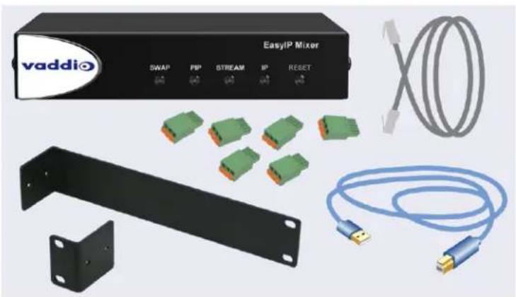
Product photo of a EasyIP Mixer device with various connectors and cables (no visible text or symbols)The box should contain these items:
■ EasyIP Mixer
■ USB 3.0 cable, type A to type B, 6 ft (1.8 m)
■ Cat-5e cable, 3 ft (0.9 m)
■ 3-position Phoenix-style connectors (qty. 6)
■ Half-rack mounting kit
■ Quick-Start Guide
EasyIP 10 AV-over-IP PTZ Camera
Worldwide: 999-30200-000 (black), 999-30200-000W (white)

natural_image
Product photo of a video camera setup with remote control, cable, and paper (no visible text or symbols)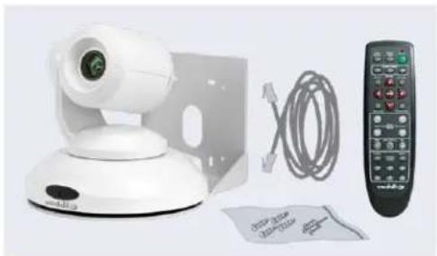
natural_image
White remote control device with camera, cable, and remote control (no visible text or symbols)The box should contain these items:
■ Camera (black or white)
■ Vaddio IR Remote Commander
■ Thin Profile Wall Mount with mounting hardware
■ Cat-5e cable, 10 ft. (3 m)
■ Quick-Start Guide
Caution
When lifting or moving a camera, always support the camera's base. Lifting the camera by its height mounting arm will damage it.

EasyIP 20 AV-over-IP PTZ Camera
Worldwide: 999-30230-000 (black), 999-30230-000W (white)
natural_image
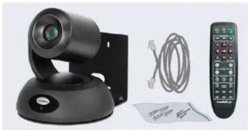
Product photo of a black video camera with attached cable and remote control (no visible text or symbols)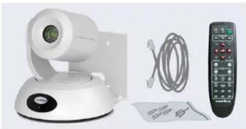
natural_image
Product photo of a white video camera with attached cable and remote control (no visible text or symbols)The box should contain these items:
■ Camera (black or white)
■ Vaddio IR Remote Commander
■ Thin Profile Wall Mount with mounting hardware
■ Cat-5e cable, 10 ft. (3 m)
■ Quick-Start Guide
Caution
When lifting or moving a camera, always support the camera's base. Lifting the camera by its height mounting arm will damage it.

A Quick Look at the EasyIP Family
■ EasyIP Decoder – Decodes the AV-over-IP signal from the camera(s) and originates a USB stream.
- EasyIP Mixer – Pro A/V capabilities for the EasyIP environment.
- EasyIP 10 camera – Great video, 10x zoom, simple installation, minimal set-up.
- EasyIP 20 camera – The same great video and simple installation as the EasyIP 10, but with 20x zoom, CCU scenes, and other additional capabilities.
EasyIP Decoder
The EasyIP Decoder receives and decodes the AV-over-IP signal from the camera(s) and originates a USB stream.
Front View

Status light – Provides basic information about the device.
■ Illuminated: Normal operation.
■ Off: No power to the device.
■ Blinking: Error.
IP Address button – Press to display the decoder's IP address in its USB stream.
Dimensionally enhanced logo badge – We have spared no expense to provide a puffy logo badge to elevate your experience. It's quite shiny, and offers superior tactile appeal.
Back View

■ Network/PoE+ – RJ-45 connector. Connect to a powered port on the PoE+ switch.
- USB 3.0 – USB Type B connector. Connect to a computer for use with soft conferencing applications. Provides uncompressed USB 3.0 stream.
- EasyMic – RJ-45 connectors. Connect to a TableMIC or other microphone with EasyMic connectivity.
- Audio output – Line level differential audio and 12 VDC power output to the optional amplified speaker or other audio infrastructure.
EasyIP Mixer
Ideal for large classrooms and multi-camera applications, the EasyIP Mixer pairs to Dante audio inputs and outputs, and manages up to four Vaddio EasyIP cameras. It's the Art of Easy in a production switcher.
Front View

- Swap button – Changes the selected input. If the PIP is turned on, this also exchanges the PIP and main image on the HDMI output.
- PIP button – Toggles the PIP on or off. Illuminated when the PIP is on.
Stream button – Toggles HDMI and USB stream on or off. Illuminated when the stream is available. - IP button – Toggles the IP address display. Illuminated when the streams are displaying the IP address instead of video.
- Reset button and power/status light – Illuminated when the device has power. Blinks to indicate an error condition. Press the button to reboot the device.
■ Dimensionally enhanced logo badge – The same lustrous bit of tactile interest that you know and love from other Vaddio equipment.
Back View

■ Network/PoE – Power, control via web interface, and Dante audio.
■ USB 3.0 – Uncompressed video output with PCM audio for conferencing applications.
■ RS-232 – Connect to an optional third-party control system.
- Trigger – Connect up to five trigger devices.
■ HDMI In – Video (and audio, if available) from a connected camera or other HDMI source.
■ HDMI Out - Output video (and audio, if available) from the selected input.
■ Audio In Mic/Line In 1 and Mic/Line In 2 – Microphone or other audio inputs. Can be configured to supply phantom power.
- Audio Out Line Out 1 and Line Out 2 – Far-end audio from conferencing application or as configured in the audio matrix.
EasyIP 10 Camera
The EasyIP 10 camera delivers great video with simple installation and minimal set-up. Use it with an EasyIP Decoder or EasyIP Mixer.
Front View
natural_image
Black Vaddio camera on a tripod stand (no visible text or symbols)Camera and zoom lens - 10X zoom lens.
IR sensor - Receives signals from the IR remote.
Status light - Multi-colored LED that indicates the camera's current state.
■ Blue - Camera is active
■ Purple – Standby mode or booting
■ Yellow – Firmware update is in progress
■ Blinking red – Video mute is on (UC color scheme)
■ Blinking yellow – Motor out of calibration
Back View

natural_image
Black remote control device with a circular dial and antenna, mounted on a base (no visible text or symbols)Network/PoE+ - RJ-45 connector. Connect to a powered port on the PoE+ switch. It doesn't get much easier than that, does it?
EasyIP 20 Camera
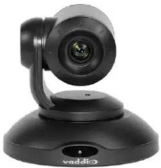
The EasyIP 20 camera provides greater zoom and more sophisticated capabilities than the EasyIP 10 camera. Use it with an EasyIP Decoder or EasyIP Mixer.
Front View

natural_image
Black remote camera on a stand with a circular display and control buttons (no visible text or symbols)Camera and zoom lens - 20X zoom lens.
IR sensor - Receives signals from the IR remote.
Status light - Multi-colored LED that indicates the camera's current state.
■ Blue - Camera is active
■ Purple – Standby mode or booting
■ Yellow – Firmware update is in progress
■ Blinking red – Video mute is on (UC color scheme)
Back View

natural_image
Black remote control device with ports and antenna (no visible text or symbols)■ Network/PoE+ – RJ-45 connector. Connect to a powered port on the PoE+ switch.
- HD Video Select switch – Rotary switch to select the video output resolution. A label on the bottom of the camera lists the rotary switch settings.
■ HDMI – Local HDMI video output to an optional display.
■ RS-232 – Allows an external device to manage the camera using a modified VISCA protocol. See RS-232 Serial Communication Settings.
Installation
This section covers:
■ Tips for selecting camera locations
■ Cabling notes
■ Installing the camera mount and mounting the camera
■ System connection diagrams with cameras and audio peripherals
And a required safety note here:
Note
PoE type networks connected to this equipment are for intra-building use only and should not be to lines that run outside of the building in which this product is located.
Cameras and network-connected audio peripherals must be paired to the host device after the installation is complete.
Contact Vaddio Technical Support if you have questions or encounter any problems. Phone 800.572.2011 / +1.763.971.4400, email av.vaddio.support@legrand.com.
Don't Void Your Warranty!

Caution
When handling cameras, always support the camera's body when lifting or moving it. Lifting the head or mounting arm will damage it.
Caution
EasyIP products are for indoor use. Do not install these products outdoors or in a humid enviro without the appropriate protective enclosure.
Caution
Do not install or operate any EasyIP product if it has been dropped, damaged, or exposed to of these things happen, return the product to Vaddio for safety and functional testing.
Before You Start
Work with the network administrator to plan your EasyIP deployment. A typical EasyIP system includes network equipment.
Do these things before installing any Vaddio product:
■ Be sure you can identify all cables correctly.
■ Check Cat-5 cables for continuity.
■ Talk to the network administrator.
Inform the network administrator if you are installing the EasyIP system with a PoE+ switch. The Luxul switch sold as part of the EasyIP ecosystem is configured for DHCP operation. The network administrator may need to take steps to ensure a trouble-free installation.
If you will be responsible for configuring the devices that you install, ask what hostnames (if any) you should assign to them.
Before Installing Cameras
Things to keep in mind when deciding where to install the camera:
- Consider camera viewing angles, lighting conditions, line-of-sight obstructions, and in-wall obstructions where the camera is to be mounted.
■ Ensure that the camera body can move freely and will normally point away from the ceiling and lights.
The camera will not perform well if it is pointed toward a light source such as a light fixture or window.
■ If the remote will be used, ensure that nothing blocks the IR lens in the camera's base.
Cabling Notes
The TableMIC is shipped with one Cat-5e cable to connect it to your conferencing installation.
The CeilingMIC is shipped with one Cat-5e cable to connect it to the interface box.
Caution
When building cables for Vaddio products, do not use pass-through RJ-45 connectors. Incorrectly crimped pass-through connectors can damage the connectors on the product, which will void your warranty.

Intact - will make reliable contact with cable connector

Damaged – Bent contact fingers will NOT make reliable contact with cable connector
Use Cat-5e or better cable. We recommend using high-quality connectors and a high-quality crimping tool. If connectors are crimped incorrectly, they can cause intermittent connections and degrade signal quality.
We recommend shielded cabling if the cables will be coiled, run tightly with other cables, or routed near sources of electromagnetic interference such as power lines or fluorescent light fixtures.
Caution
Check your cables. Connecting a cable to the wrong port or using the wrong pin-out can result damage and will void the warranty.
Pro Tip
Label all cables at both ends.
RS-232 Serial Communication Settings and Port Pin-outs
The EasyIP Mixer and EasyIP 20 camera have RS-232 serial ports (color-coded blue) to connect to a third-party controller.
Depending on the equipment connected to the RS-232 port, you may need a null-modem (crossover) cable.
Caution
Check your cables. Connecting a cable to the wrong port or using the wrong pin-out can result damage and will void the warranty.
EasyIP Mixer
RS-232 connector pin-out:
■ Pin 1: Not used
■ Pin 2: Not used
■ Pin 3: Not used
■ Pin 4: Not used
■ Pin 5: Not used
■ Pin 6: GND
■ Pin 7: TXD (to RXD of connected device)
■ Pin 8: RXD (from TXD of connected device)

Communication parameters:
| Parameter Value | |
| Communication Speed 38400 | baud |
| Start bits 1 | |
| Stop bits 1 | |
| Data bits 8 | |
| Parity None | |
| Flow control None |
EasyIP 20 Camera
RS-232 connector pin-out:
■ Pin 1: Not used
■ Pin 2: Not used
■ Pin 3: Not used
■ Pin 4: Not used
■ Pin 5: Not used
■ Pin 6: GND
■ Pin 7: RXD (to TXD of host device)
■ Pin 8: TXD (from RXD of host device)
Communication parameters:
| Parameter Value | |
| Communication Speed 9600 or 38400 baud, selectable | |
| Start bits 1 | |
| Stop bits 1 | |
| Data bits 8 | |
| Parity None | |
| Flow control None | |

Basic Connections - EasyIP Decoder
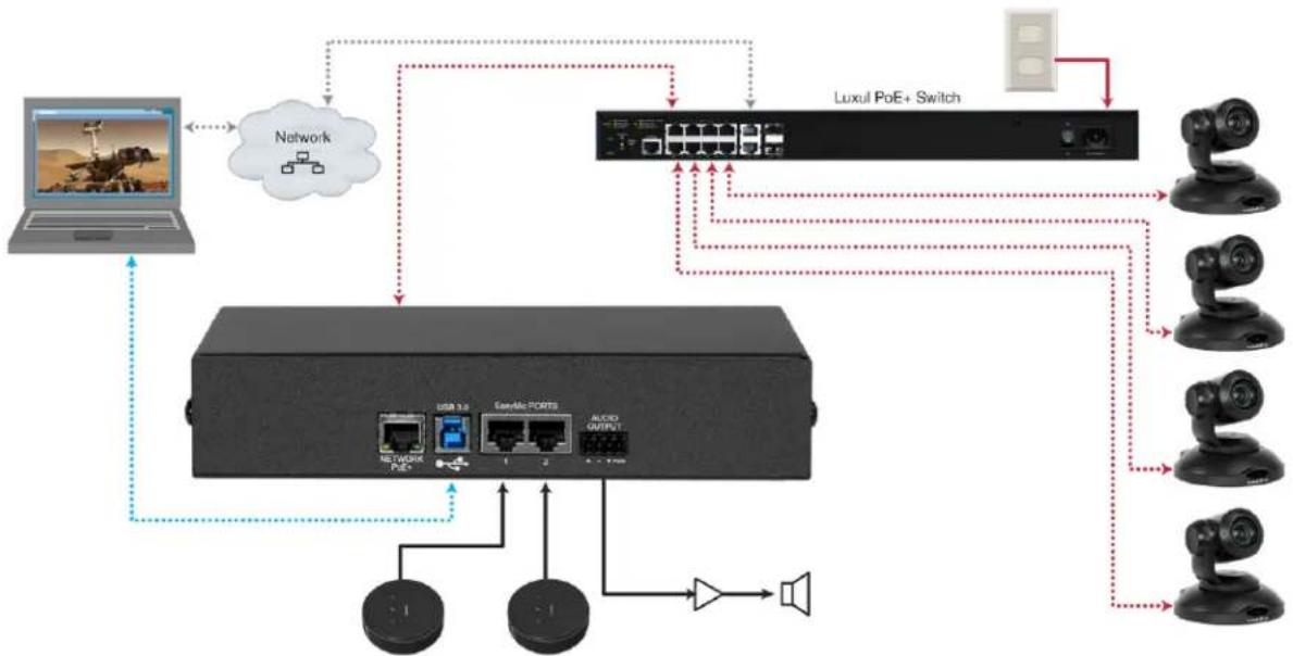
Here is an example of a simple EasyIP deployment. In this setup, an EasyIP Decoder manages up to four EasyIP cameras and provides hard-wired audio connections. A PoE+ switch provides power and network connectivity to the EasyIP products. The EasyIP Decoder connects directly to a computer as a USB conferencing device.
Vaddio recommends making all connections while the PoE+ switch is turned off.
If no PoE+ switch is used, a mid-span PoE+ power injector (sold separately) is required for each EasyIP device.
flowchart
graph TD
    A["Laptop"] --> B["Network"]
    B --> C["Network Switch"]
    C --> D["Luxul PoE+ Switch"]
    D --> E["Camera 1"]
    D --> F["Camera 2"]
    D --> G["Camera 3"]
    D --> H["Camera 4"]
    D --> I["Camera 5"]
    D --> J["Camera 6"]
    D --> K["Camera 7"]
    D --> L["Camera 8"]
    D --> M["Camera 9"]
    D --> N["Camera 10"]
    D --> O["Camera 11"]
    D --> P["Camera 12"]
    D --> Q["Camera 13"]
    D --> R["Camera 14"]
    D --> S["Camera 15"]
Caution
Do not connect the PoE+ switch to the network without guidance from an on-site network special
Note
EasyIP cameras require an EasyIP Decoder or EasyIP Mixer to decode the AV-over-IP signal and a USB stream.
The EasyIP Decoder is compatible with EasyIP cameras only. It does not detect or pair with other cameras.
Basic Connections - EasyIP Mixer
Here is an example of an EasyIP deployment using an EasyIP Mixer. In this setup, the EasyIP Mixer manages up to four EasyIP cameras and provides hard-wired audio connections for speakers. The EasyIP Mixer is paired to two network-connected EasyIP CeilingMIC D microphones. A computer connects to the system as a USB conferencing device and HDMI content source.
A PoE+ switch provides power and network connectivity to the EasyIP products. If no PoE+ switch is used, a mid-span PoE+ power injector (sold separately) is required for each EasyIP device.
Vaddio recommends making all connections while the PoE+ switch is turned off.

flowchart
graph TD
    A["User"] --> B["Network"]
    B --> C["Server"]
    C --> D["Audio Output"]
    D --> E["Output 1"]
    D --> F["Output 2"]
    D --> G["Output 3"]
    H["Network"] --> I["User"]
    I --> J["Server"]
    J --> K["Audio Output"]
    K --> L["Output 1"]
    K --> M["Output 2"]
    N["VoE+"] --> O["User"]
    P["Network"] --> Q["User"]
    R["Video"] --> S["User"]
    T["Audio"] --> U["User"]
Caution
Do not connect the PoE+ switch to the network without guidance from an on-site network special
Note
The EasyIP Mixer is compatible with EasyIP cameras only. It does not detect or pair with other cameras.
Basic Connections – EasyIP Mixer with HDMI Input from EasyIP 20 Camera
The EasyIP Mixer can only decode one EasyIP stream at a time. To allow the EasyIP Mixer to use an EasyIP 20 camera as the PIP source while another EasyIP camera provides the main video, connect the EasyIP 20 camera's HDMI output to the EasyIP Mixer's HDMI In port. This camera can provide the PIP when any paired EasyIP camera is selected as the main video. When the HDMI-connected camera is selected as the main video, any paired EasyIP camera can serve as the PIP source.

flowchart
graph TD
    A["Network"] --> B["Pod"]
    B --> C["USB 3.0"]
    C --> D["RS-232"]
    D --> E["TIGGER 1-2 3"]
    E --> F["4 5 V"]
    F --> G["HOME IN"]
    G --> H["+ - V"]
    H --> I["MIC LINE 1"]
    I --> J["+ - V"]
    J --> K["Audio OUT"]
    K --> L["LINE 1"]
    K --> M["LINE 2"]
    K --> N["+ - V"]
    N --> O["Audio OUT"]
    O --> P["Line 1"]
    O --> Q["Line 2"]
    P --> R["Speaker"]
    Q --> S["Speaker"]
    R --> T["+ - V"]
    S --> U["Speaker"]
    T --> V["+ - V"]
    U --> W["+ - V"]
    V --> X["+ - V"]
    W --> Y["+ - V"]
    X --> Z["+ - V"]
    Y --> AA["+ - V"]
    Z --> AB["+ - V"]
    AA --> AC["+ - V"]
    AB --> AD["+ - V"]
    AC --> AE["+ - V"]
    AD --> AF["+ - V"]
    AE --> AG["+ - V"]
    AF --> AH["+ - V"]
    AG --> AI["+ - V"]
    AH --> AJ["+ - V"]
    AI --> AK["+ - V"]
    AJ --> AL["+ - V"]
    AK --> AM["+ - V"]
    AL --> AN["+ - V"]
    AM --> AO["+ - V"]
    AN --> AP["+ - V"]
    AO --> AQ["+ - V"]
    AP --> AR["+ - V"]
    AQ --> AS["+ - V"]
    AR --> AT["+ - V"]
    AS --> AU["+ - V"]
    AT --> AV["+ - V"]
    AU --> AW["+ - V"]
    AV --> AX["+ - V"]
    AW --> AY["+ - V"]
Installing the Wall Mount for the Camera
EasyIP cameras are shipped with wall mounts. Other mounting options are available as well. Contact us if you don't have the camera mount you need.
You can install the camera wall mount to a 2-gang wall box or directly to the drywall.
■ If you mount it to drywall, use the wall anchors provided with the wall mount.
■ If you mount it to a wall box, use the cover plate screws supplied with the wall box.
If you install the camera wall mount to drywall, use the wall anchors provided with the mount.

Your camera mount may look somewhat different.
About Ceiling-Mounted Cameras
If you use an inverted mount, set the camera's Image Flip mode ON for inverted operation. This orients the video image correctly and sets the tilt motors to respond appropriately to tilt up and down commands from the remote, web interface, and connected control devices. This control is available to the administrator on the web interface's System page.
Installing the Camera
-
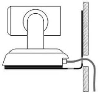
Route the cable through the opening in the mounting shelf and connect it to the camera.
-
Place the camera on the mount.
natural_image
Simple line drawing of a computer monitor with a cable and wall, no text or symbols presentImage for illustration only; not to scale. Camera and mount details may differ.
- Attach the camera to the mount using the mounting screw supplied with the camera.

Note
EasyIP 10 camera only: If the camera is jostled or bumped while it is connected to power, it m pan-tilt reset.
Powering Up the EasyIP System
Vaddio recommends making all connections while the PoE+ switch is turned off. To power the system, turn on the PoE+ switch.
■ The EasyIP Decoder's status light turns blue when the device is ready. The connected computer recognizes it as a USB peripheral.
- The EasyIP cameras initialize and move if they are powered from the same PoE+ switch. This will take a few seconds. When each camera's status light turns blue, the camera is ready to accept control information.
- The EasyIP Mixer's power light in the Reset button illuminates immediately when power is connected. The device's web interface is available after it finishes booting. This takes about 20 seconds.
Note
If a camera has already been in use and is paired with the host device, its indicator light may when it finishes booting. This happens if the camera is the selected video input and is using to color scheme. Pro A/V is the default color scheme for EasyIP 20 cameras.
Next Steps
No video is available from the EasyIP system until it is configured. Refer to the Complete Manual for the EasyIP System for information on initial device set-up and pairing EasyIP 10 cameras to the EasyIP Decoder.
Operation, Storage, and Care
For smears or smudges on the product, wipe with a clean, soft cloth. Use a lens cleaner on the lens. Do not use any abrasive chemicals.
Keep this device away from food and liquids.
Do not operate or store the device under any of the following conditions:
■ Temperatures above 104^ F ( 40^ C) or below 32^ F ( 0^ C)
■ High humidity, condensing or wet environments
■ Inclement weather
■ Severe vibration
■ Under the sea, in an octopus's garden
■ Dry environments with an excess of static discharge
Do not attempt to take this product apart. There are no user-serviceable components inside.
Compliance and Conformity Statements
Compliance testing was performed to the following regulations:
| FCC Part 15 (15.107, 15.109), Subpart B Class A | |
| ICES-003, Issue 54: 2012 Class A | |
| EMC Directive 2014/30/EU Class A | |
| EN 55032: 2015 Class A | |
| EN 55024: November 2010 Class A | |
| IEC 60950-1:2005 (2nd Edition); Am 1: 2009 + Am 2: 2013 Safety | |
| EN 60950-1: 2006 + A11: 2009 + A1: 2010 + A12: 2011 + A2: 2013 Safety | |
| IEC 62368-1:2014 (2nd Edition) Safety |
FCC Part 15 Compliance
This equipment has been tested and found to comply with the limits for a Class A digital device, pursuant to Part 15, Subpart B, of the FCC Rules. These limits are designed to provide reasonable protection against harmful interference when the equipment is operated in a commercial environment. This equipment generates, uses, and can radiate radio frequency energy and, if not installed and used in accordance with the instruction manual, may cause harmful interference to radio communications. Operation of this equipment in a residential area is likely to cause harmful interference in which case the user will be required to correct the interference at his/her own expense.
Operation is subject to the following two conditions: (1) This device may not cause interference, and (2) This device must accept any interference including interference that may cause undesired operation of the device.

Changes or modifications not expressly approved by Vaddio can affect emission compliance and could void the user's authority to operate this equipment.
ICES-003 Compliance
This digital apparatus does not exceed the Class A limits for radio noise emissions from digital apparatus set out in the Radio Interference Regulations of the Canadian Department of Communications.
This product has been evaluated for Electromagnetic Compatibility under the EMC Directive for Emissions and Immunity and meets the requirements for a Class A digital device. In a domestic environment this product may cause radio interference in which case the user may be required to take adequate measures.
Standard(s) To Which Conformity Is Declared:

EMC Directive 2014/30/EU
EN 55032: 2015 – Conducted and Radiated Emissions
EN 55024: November 2010 – Immunity
IEC 60950-1: 2005 (2nd Edition); Am 1: 2009 + Am 2: 2013 – Safety
EN 60950-1: 2006 + A11: 2009 + A1: 2010 + A12: 2011 + A2: 2013 - Safety
IEC 62368-1: 2014 (2nd Edition) – Safety
Photo Credits
This guide may include some or all of these photos.
European Space Agency (ESA) astronaut Samantha Cristoforetti, a Flight Engineer with Expedition 42, photographs the Earth through a window in the Cupola on the International Space Station
By NASA - https://blogs.nasa.gov/ISS_Science_Blog/2015/03/06/women-in-space-part-two-whats-gender-got-to-do-with-it/, Public Domain, https://commons.wikimedia.org/w/index.php?curid=38834990
Carl Sagan, Bruce Murray, Louis Friedman (founders) and Harry Ashmore (advisor), on the occasion of signing the papers formally incorporating The Planetary Society
By credit NASA JPL - JPL, Public Domain, https://commons.wikimedia.org/w/index.php?curid=1180927
Main Control Room / Mission Control Room of ESA at the European Space Operations Centre (ESOC) in Darmstadt, Germany
By European Space Agency - ESOC flickr, Credit: ESA - Jürgen Mai, CC BY-SA 3.0-igo, https://commons.wikimedia.org/w/index.php?curid=36743173
Expedition 42 on orbit crew portrait, International Space Station, Mar. 7, 2015 – Barry Wilmore (Commander) Top, Upside down, to the right cosmonaut Elena Serova, & ESA European Space Agency Samantha Cristoforetti. Bottom center US astronaut Terry Virts, top left cosmonauts Alexander Samokutyaev and Anton Shkaplerov.
By NASA - https://www.flickr.com/photos/nasa2explore/16166230844/, Public Domain, https://commons.wikimedia.org/w/index.php?curid=38931301
European Space Agency astronaut Luca Parmitano, Expedition 36 flight engineer, outside the International Space Station
By NASA - http://spaceflight.nasa.gov/gallery/images/station/crew-36/html/iss036e016704.html, Public Domain, https://commons.wikimedia.org/w/index.php?curid=27263573
Chris Cassidy, Luca Parmitano, and Karen Nyberg, ISS, 2013. Photo Credit: NASA
Nicolas Altobelli, Rosetta Scientist at ESA's European Space Astronomy Centre, Villanueva de la Cañada, Madrid, Spain
By European Space Agency - Nicolas Altobelli talks to the media, CC BY-SA 3.0-igo, https://commons.wikimedia.org/w/index.php?curid=36743144
Andrea Accomazzo, ESA Rosetta Spacecraft Operations Manager, providing a live update from the Main Control Room at ESA's European Space Operations Centre, Darmstadt, Germany during the Rosetta wake-up day.
By European Space Agency - Live update from the Main Control Room, CC BY-SA 3.0-igo, https://commons.wikimedia.org/w/index.php?curid=36743150
Sleeping goose
By ladypine - Own work, CC BY-SA 3.0, https://commons.wikimedia.org/w/index.php?curid=1695227
By Rick Dikeman - Image:Wayne Gretzky 1997.jpg, CC BY-SA 3.0, https://commons.wikimedia.org/w/index.php?curid=945698
Photo AS11-40-5948, Aldrin assembles seismic experiment, by National Aeronautics and Space Administration, courtesy of the NASA History Office and the NASA JSC Media Services Center Author's own cats, photos by author, you're welcome.
Index
A
anatomy of the camera 10-11
anatomy of the decoder 8
anatomy of the mixer 9
audio 8-9
ports 8-9
B
baud rate 14-15
behavior on power-up 21
buttons and indicators 8-9
C
cable 8-11, 13-15
connectors 8-11, 13
RS-232 pin-out 14-15
camera mount 19-20
cameras 13
placement 13
capabilities 3-4
ceiling-mounted cameras 19
cleaning 21
connection diagram 16-18
connectors 8-11
D
damage, preventing 5-7, 12-15
diagram, connection 16-18
E
EasyIP basics 2
H
HDMI In port 9
HDMI Out port (camera) 11
HDMI Out port (EasyIP Mixer) 9
|
indicator light 8-11
meaning of colors 8, 10-11
installation 16-20
camera 20
camera mount 19
inverted 19
typical 16-18
inverted installation 19
IP address 8-9
decoder, discovering 8
EasyIP Mixer, discovering 9
L
location of the camera 13
locations of connectors 8-11
M
minimum requirements, EasyIP system 16-18
mount 19-20
installing 19
mounting the camera 20
N
network port 8-11
0
operating environment 12, 21
P
packing list 5-7
part numbers 5-7
pin-out, RS-232 14-15
PIP 18
source, from EasyIP camera 18
PoE+ port 8-11
power on/power off 21
precautions 5-7, 12
for operating the system 12
product capabilities 3-4
puffy logo badge 8-9
R
requirements 2, 12-13, 16-19
EasyIP system 2
installation 12-13, 16-19
network 12
RJ-45 connectors 13
RS-232 14-15
cable pin-out 14-15
communication settings 14-15
RS-232 port 9, 11
S
shelf-mounted cameras 20
shelf, camera mount 19
site requirements 13
status light 8-11
behavior 8, 10-11
storage environment 21
switch settings 19
T
temperature, operating and storage 21
trigger ports 9
U
USB port 8-9
V
visual packing list 5-7
visual parts identification 8-11
W
wall mount 19
installing 19
warranty 12
Vaddio is a brand of Legrand AV Inc.· www.legrandav.com · Phone 800.572.2011 / +1.763.971.4400 · Fax +1.763.971.4464 · Email av.vaddio.support@legrand.com·
Visit us at www.legrandav.com for firmware updates, specifications, drawings, manuals, technical support information, and more.
©2020 Legrand AV Inc.
Vaddio is a registered trademark of Legrand AV Inc. Audinate®, the Audinate logo and Dante® are registered trademarks of Audinate Pty Ltd. All other brand names or marks are used for identification purposes and are trademarks of their respective owners. All patents are protected under existing designations. Other patents pending.
A brand of legrand®
Commercial AV Brands Chief | Da-Lite | Middle Atlantic | Projecta | Vaddio
vaddio®

- EasyIP Systems
- Contents
- Installation Guide for EasyIP Systems
- Overview
- What's in this Guide
- This guide covers:
- EasyIP Systems.
- Note
- The EasyIP Ecosystem
- EasyIP Decoder
- EasyIP Mixer
- EasyIP Cameras
- EasyIP Switch
- EasyIP Decoder Features
- EasyIP Mixer Features
- EasyIP 10 Camera Features
- EasyIP 20 Camera Features
- Unpacking the EasyIP System Components
- EasyIP Decoder AV-over-IP Switching USB Endpoint
- EasyIP Mixer AV Switcher
- EasyIP 10 AV-over-IP PTZ Camera
- Caution
- EasyIP 20 AV-over-IP PTZ Camera
- A Quick Look at the EasyIP Family
- Front View
- Back View
- EasyIP 10 Camera
- EasyIP 20 Camera
- Installation
- Don't Void Your Warranty!
- Before You Start
- Before Installing Cameras
- Cabling Notes
- Pro Tip
- RS-232 Serial Communication Settings and Port Pin-outs
- RS-232 connector pin-out:
- Basic Connections - EasyIP Decoder
- Basic Connections - EasyIP Mixer
- Basic Connections – EasyIP Mixer with HDMI Input from EasyIP 20 Camera
- Installing the Wall Mount for the Camera
- About Ceiling-Mounted Cameras
- Installing the Camera
- Powering Up the EasyIP System
- Next Steps
- Operation, Storage, and Care
- Compliance and Conformity Statements
- FCC Part 15 Compliance
- ICES-003 Compliance
- Photo Credits
- Index
- A
- B
- C
- D
- E
- H
- |
- L
- M
- N
- 0
- P
- R
- S
- T
- U
- V
- W
- A brand of legrand®
Brand : Vaddio
Model : EasyIP 20
Category : Security Camera