
DS-XS10G-P - Network switch Hikvision - Free user manual and instructions
Find the device manual for free DS-XS10G-P Hikvision in PDF.


| Product Type | Network Switch |
| Model | DS-XS10G-P |
| Brand | Hikvision |
| Ports | 10 x 10/100/1000 Mbps Gigabit Ethernet ports |
| PoE Support | Yes, IEEE 802.3at/af PoE+ on all ports |
| Power over Ethernet Budget | 130 W |
| Switching Capacity | 20 Gbps |
| Mac Address Table | 8K entries |
| Dimensions (W x D x H) | 330 x 230 x 44 mm |
| Weight | 2.5 kg |
| Power Supply | AC 100-240V, 50/60Hz |
| Power Consumption | Max 150 W (with PoE) |
| Operating Temperature | 0°C to 40°C |
| Storage Temperature | -40°C to 70°C |
| Main Functions | Layer 2 switching, VLAN, QoS, IGMP snooping, PoE management |
| Maintenance & Cleaning | Disconnect power before cleaning; use dry cloth; avoid liquids |
| Safety | CE, FCC compliant; indoor use only; avoid overheating |
| Spare Parts & Repairability | Contact Hikvision support for replacement parts; no user-serviceable parts |
| General Information | Designed for surveillance systems and small to medium networks |
Frequently Asked Questions - DS-XS10G-P Hikvision
User questions about DS-XS10G-P Hikvision
0 question about this device. Answer the ones you know or ask your own.
Ask a new question about this device
Download the instructions for your Network switch in PDF format for free! Find your manual DS-XS10G-P - Hikvision and take your electronic device back in hand. On this page are published all the documents necessary for the use of your device. DS-XS10G-P by Hikvision.
USER MANUAL DS-XS10G-P Hikvision
- This Document includes instructions for using and managing the Product Pictures, charts, images and all other information hereinafter are for description and explanation only.
- The information contained in the Document is subject to change, without notice, due to firmware updates or other reasons. Please find the latest version of the Document at the Hikvision website (https://www.hikvision.com). Unless otherwise agreed, Hangzhou Hikvision Digital Technology Co., Ltd. or its affiliates (hereinafter referred to as "Hikvision") makes no warranties, express or implied.
- Please use the Document with the guidance and assistance of professionals trained in supporting the Product.
About this Product
This product can only enjoy the after-sales service support in the country or region where the purchase is made.
Acknowledgment of Intellectual Property Rights
- Hikvision owns the copyrights and/or patents related to the technology embodied in the Products described in this Document, which may include licenses obtained from third parties.
- Any part of the Document, including text, pictures, graphics, etc., belongs to Hikvision. No part of this Document may be excerpted, copied, translator or modified in whole or in part by any means without written permission.
• PARATHYATION's trademarks and logos are the
properties of Hikvision in various jurisdictions. - Other trademarks and logos mentioned are the properties of their respective owners.
LEGAL DISCLAIMER
• TOTHERMAXIMUM EXTENDED BY APPLICABLE LAW, THIS DOCUMENT AND THE PRODUCT DESCRIBLED, WITH IT'S HARDWARE, SOFTWARE AND FIRMWARE, ARE PROVIDED AS IS IN' AND "WITH ALL FAULTS AND ERRORS", HIKVISION MAKES NO WARRANTIES, EXPRESS OR IMPLIED, INCLUDING WITHOUT LIMITATION, MERCHANTABILITY, SATISAFORY QUALITY, OR FITNESS FOR A PARTICULAR PURPOSE. THE USE OF THE PRODUCT BY YOU IS AT YOUR OWN RISK. IN NO EVENT WILL HIKVISION BE LIABLE TO YOU FOR ANY SPECIAL, CONSEQUENTIAL, INCIDENTAL, OR INDIRECT DAMAGES, INCLUDING, AMONG OTHERS, DAMAGES FOR LOSS OF BUSINESS PROFITS, BUSINESS INTERRUPTION, OR LOSS OF DATA, CRUPTION OF SYSTEMS, CROSSSED DOCUMENTATION, WHETHER BASED ON BREACH OF CONTRACT, TORT (INCLUDING NEGLIGENCE), PRODUCT LIABILITY, OR OTHERWISE, IN CONNECTION WITH THE USE OF THE PRODUCT, EVEN IF HIKVISION HAS BEEN ADVISED OF THE POSSIBILITY OF SUCH DAMAGES OR LOSS.
- YOU ACKNOWLEDGE THAT THE NATURE OF THE INTERNET PROVIDES FOR INHERENT SECURITY RISKS, AND HIKVISION SHALL NOT TAKE ANY RESPONSIBILITY FOR AN NORMAL OPERATION, PRIVACYLEAKAGED DROTHER DAMAGES RESULTING FROM CYBER ATTACK, HACKER ATTACK, VIRUS INFECTION, OR OTHER INTERNET SECURITY RISKS. HOWEVER, HIKVISION WILL PROVIDE TIMELY TECHNICAL SUPPORT IF REQUIRED.
- YOU AGREE TO USE THIS PRODUCT IN COMPLIANCE WITH ALL APPLICABLE LAWS, AND YOU ARE SOLELY RESPONSIBLE FOR ENSURING THAT YOUR USL/CONFORMS ITITH/APPLICABLE LAW, ESPECIALLY, YOUR ALRESPRESIBLE, FOR USING THIS PRODUCT IN A MANNER THAT DOES NOT INFRINGEMENT ON THE RIGHTS OF THIRD PARTIES, INCLUDING WITHOUT LIMITATION, RIGHTS OF PUBLICITY, INTELUCTUAL PROPERTY RIGHTS, OR DATA PROTECTION AND OTHER PRIVACY RIGHTS. YOU SHALL NOT USE THIS PRODUCT FOR ANYPROHIBITED ENDS, INCLUDING THE DEVELOPMENT NOR PRODUCTION OF WEAPONS OF MASS DESTRUCTION, THE DEVELOPMENT OR PRODUCTION OF CHEMICAL, OR BIOLOGICAL WEAPONS, ANY ACTIVITIES IN THE CONTEXT RELATED TO ANY NUCRELATIVE OPPOSITE OR UNSAFE NUCREL FUEL-CYCLE, OR IN SUPPORT OF HUMAN RIGHTS ABUSES.
- IN THE EVENT OF ANY CONFLICTS BETWEEN THIS DOCUMENT AND THE APPLICABLE LAW, THE LATTER PREVAILS.
© Hangzhou Hikvision Digital Technology Co., Ltd. All rights reserved.
Preface
Applicable Models
This manual is applicable to switches.
Symbol Conventions
The symbols that may be found in this document are defined as follows.
| Symbol | Description |
| Note | Provides additional information to emphasize or supplement important points of the main text. |
| Caution | Indicates a potentially hazardous situation, which if not avoided, could result in equipment damage, data loss, performance degradation, or unexpected results. |
| Danger | Indicates a hazard with a high level of risk, which if not avoided, will result in death or serious injury. |

Learn About Your Switch
▷ Front Panel (Example)
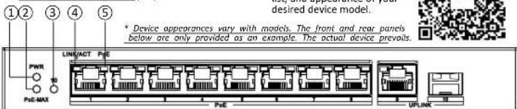
▷ Rear Panel (Example)

Ports
PoE RJ45 Port

10/100 Mbps or gigabit PoE RI45 port, used for connection to a powered device (PD) via a network cable.
RJ45 Port

10/100 Mbps or gigable RJ45 port, used for connection to another device via a network cable.
SFP Fiber Optical Port

Gigabit SFP fiber optical port, used for connection to another device via an optical fiber when the port is plugged into with an optical module.
High-Priority Port

Red port (or VIP port), used to preferentially ensure network transmission in key service areas.
| Indicators | 1 PWR Indicator | Solid on: The switch is powered on normally.Unlit: No power supply is connected or power supply is abnormal. |
| 2 PoE-MAX Indicator | Solid on: The output power of the switch is about to reach or has reached the upper limit.The power supply may be abnormal if more devices are connected.Unlit: The switch does not supply power to a PD, or supplies power to a PD normally and its output power does not reach the upper limit. The PoE-MAX indicator will be unlit in 5 seconds after the output power of the switch returns to normal. | |
| 3 Optical Port Indicator | Solid on: The gigabit SFP fiber optical port is connected.Flashing: The gigabit SFP fiber optical port is transmitting data.Unlit: The gigabit SFP fiber optical port is disconnected or connection is abnormal. | |
| 4 LINK/ACT Indicator | Solid on: The port is connected.Flashing: The port is transmitting data.Unlit: The port is disconnected or connection is abnormal. | |
| 5 PoE Indicator | Solid on: The switch supplies power to a PD normally.Unlit: The switch is disconnected from a PD or power supply is abnormal. |
Others
Grounding Terminal

Used for connection to the grounding cable to protect the switch from lightning.
Reset Button

Press and hold the reset button for about 5 seconds to restore all the configurations of the switch to default settings.
Power Supply

Use the attached power cord (and power adapter, if any) to connect the switch to a power socket.

Used for switching the switch's working mode. If the corresponding indicator is solid on, it indicates that the switch works in this mode.
DIP Switch

Toggle on or off the DIP switch to enable or disable the Extend mode (specified ports of the switch support network transmission of up to 300 meters).
* The ports, indicators, etc. above are only enumerations. For more information, see Device Inform


Install Your Switch
Please select an appropriate installation method according to the actual needs.
Note
The following figures are for your reference only.
Before You Start
- Ensure that the desktop, wall, or rack is stable and firm enough.
- Keep the room well-ventilated. Leave at least 10 cm heat dissipation space around the device.
- Keep at least 1.5 cm vertical distance between two adjacent devices for rack-mounted installation.
▷ Desktop Placement
Place the device on the desk.
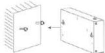
▷ Wall-Mounted Installation
Steps
- Check the distance between the two hanging holes at the bottom of the device.
- Insert two self-prepared M4 screws into the wall.
- Align the hanging holes with screws, and hang the device on the screws.
i Note
- The load-bearing capacity of the wall should be 3 times more than the weight of the device.
- Ensure that the distance between the two screws equals tothedistancebetweenthetwohangingholes.
- Set aside at least 4 mm of the screw bodies outside the wall.
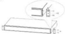
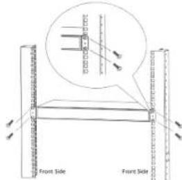
▷ Rack-Mounted Installation
Steps
- Check the grounding and stability of the rack.
- Use M3 or M4 screws provided in the package to fix the two L-shaped brackets to both sides of the device.
i Note
The number of screws provided for fixing L-shaped brackets to the device varies with device models.

- Fix two self-prepared M5 or M6 nuts to the rear side of the rack on both sides respectively.
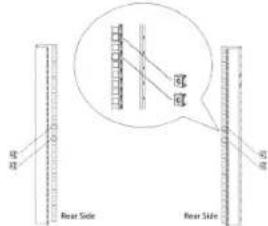
- Place the switch against the rack so that the holes on the L-shaped brackets are aligned with the holes where the nuts have been fixed.
- Fix the brackets to the front side of the rack with two self-prepared M5 or M6 screws on both sides respectively to stably install your device.
③ Ground Your Switch
Grounding is used to quickly release overvoltage and overcurrent induced by lightening for the switch, and to protect personal safety.
Select an appropriate grounding method according to your needs.
▷ With Grounding Bar
If a grounding bar is available at the installation site, follow the steps below.
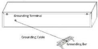

Steps
- Connect one end of the grounding cable to the binding post on the grounding bar.
- Connect the other end of the grounding cable to the device's grounding terminal and fix the screw.
▷ Without Grounding Bar
If there is no grounding bar but the earth is nearby and the grounding body is allowed to be buried, follow the steps below.
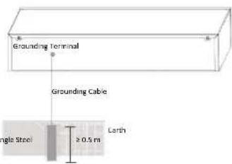
Steps
- Bury an angle steel or steel pipe (≥ 0.5 m) into the earth.
- Weld one end of the grounding cable to the angle steel or steel pipe and embalm the welding point via electroplating or coating.
- Connect the other end of the grounding cable to the device's grounding terminal.
④ Connect Your Switch to a Peer
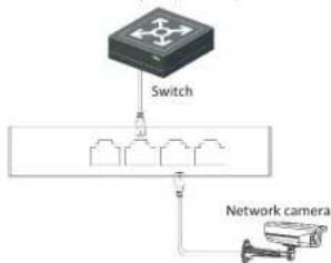
▷ RJ45 Port
Use a network cable to connect the device to the RJ45 port of a peer device such as the IP camera (IPC), network video recorder (NVR), switch, etc.
flowchart
graph TD
    A["Switch"] --> B["Device 1"]
    A --> C["Device 2"]
    A --> D["Device 3"]
    A --> E["Device 4"]
    A --> F["Device 5"]
    G["Network camera"] --> H["Device 6"]
▷ SFP Fiber Optical Port
If the device has a fiber optical port or a combo, connect the device to a peer device through an optical fiber connecting optical modules plugged into fiber optical ports respectively.

- When connected to a network cable, the combo is a RJ45 port.
- When plugged into with an optical module and connected to an optical fiber, the combo functions as a fiber optical port.
- When connected to both the network cable and optical fiber at the same time, the combo works as a fiber optical port.
Covics
- Single-mode optical modules need to be paired.
- Do not bend an optical fiber (curvature radius ≥ 10 cm) overly.
- Do not look directly at an optical fiber connector as laser is harmful to eyes.
Steps
- Connect the two paired SFP optical modules with an optical fiber.
- Hold the SFP optical module from one side, and smoothly plug it into the switch along with the SFP port slot until the optical module and the switch are closely attached.
- After powering your switch on, check the status of the LINK/ACT indicator.
- If the indicator is lit, the link is connected.
- If the indicator is unlit, the link is disconnected. Check the line, and make sure the peer device has been started.

Power Your Switch On
Please use the attached power cord (and power adapter, if any) in package to power on the device. Be Devicering your switch on, make sure that:
- The operating power supply is compliant with the rated input standard.
- Port cables and grounding cables are correctly connected.
- If there is outdoor cabling, connect a lightning rod and lightening arrester to the cable.
Caution
For PoE switches, power cables and network cables cannot be wired together, otherwise the PD or switch ports will be burnt.

Get More Information
Scan the QR code below to quickly get support on answers to FAQs.


- Preface
- Learn About Your Switch
- Ports
- Others
- Install Your Switch
- Before You Start
- ▷ Desktop Placement
- ▷ Wall-Mounted Installation
- ▷ Rack-Mounted Installation
- ③ Ground Your Switch
- ▷ With Grounding Bar
- ▷ Without Grounding Bar
- ④ Connect Your Switch to a Peer
- ▷ RJ45 Port
- ▷ SFP Fiber Optical Port
- Power Your Switch On
- Get More Information
Brand : Hikvision
Model : DS-XS10G-P
Category : Network switch