
DS-3E0116R-O - Network switch Hikvision - Free user manual and instructions
Find the device manual for free DS-3E0116R-O Hikvision in PDF.


| Product Type | Network Switch |
| Brand | Hikvision |
| Model | DS-3E0116R-O |
| Ports | 16 x 10/100/1000 Mbps RJ45 |
| Switching Capacity | 32 Gbps |
| MAC Address Table | 8K entries |
| Mounting | Rack-mountable (1U) |
| Power Supply | External AC/DC adapter, 12V DC |
| Power Consumption | ≤ 12.5 W |
| Dimensions (W x D x H) | 440 x 200 x 44 mm |
| Weight | 1.5 kg |
| Operating Temperature | 0°C to 40°C |
| Operating Humidity | 10% to 90% (non-condensing) |
| Main Functions | Unmanaged Gigabit Ethernet switch, plug-and-play, auto MDI/MDIX, store-and-forward switching |
| LED Indicators | Power, Link/Activity per port |
| Standards Compliance | IEEE 802.3, 802.3u, 802.3ab, 802.3x |
| Maintenance | Clean with a soft, dry cloth; do not use harsh chemicals |
| Safety | Keep away from liquids; do not expose to extreme temperatures; ensure proper ventilation |
| Spare Parts & Repairability | No user-serviceable parts; contact Hikvision support for repairs |
| General Information | Designed for small to medium networks, ideal for surveillance systems |
Frequently Asked Questions - DS-3E0116R-O Hikvision
User questions about DS-3E0116R-O Hikvision
0 question about this device. Answer the ones you know or ask your own.
Ask a new question about this device
Download the instructions for your Network switch in PDF format for free! Find your manual DS-3E0116R-O - Hikvision and take your electronic device back in hand. On this page are published all the documents necessary for the use of your device. DS-3E0116R-O by Hikvision.
USER MANUAL DS-3E0116R-O Hikvision
This manual is applicable to 0100 series 100 Mbps Ethernet switches.
Symbol Conventions
The symbols that may be found in this document are defined as follows.
| Symbol | Description |
 | Provides additional information to emphasize or supplement important points of the main text. |
 | Indicates a potentially hazardous situation, which if not avoided, could result in equipment damage, data loss, performance degradation, or unexpected results. |
 | Indicates a hazard with a high level of risk, which if not avoided, will result in death or serious injury. |
Safety Instructions
Danger
- This is a class A product and may cause radio interference in which case the user may be required to take adequate measures.
- Ensure that your devices powered via the PoE port have their shells protected and fire-proofed, because the switches are not compliant with the Limited Power Source (LPS) standard.
- In the use of the product, you must be in strict compliance with the electrical safety regulations of the nation and region.
- The socket-outlet shall be installed near the device and shall be easily accessible.
- The device must be connected to an earthed mains socket-outlet.
● Install the device according to the instructions in this manual. - indicates hazardous live and the external wiring connected to the terminals requires installation by an instructed person.
- Keep body parts away from fan blades. Disconnect the power source during servicing.
- Never place the device in an unstable location. The device may fall, causing serious personal injury or death.
- This device is not suitable for use in locations where children are likely to be present.
Caution
- CAUTION: Double pole/Neutral fusing. After operation of the fuse, parts of the device that remain energized might represent a hazard during servicing.
- The device has been designed, when required, modified for connection to an IT power distribution system.
-
This device is suitable for mounting on concrete or other non-combustible surface only.
-
The ventilation should not be impeded by covering the ventilation openings with items, such as newspapers, tablecloths, curtains, etc. The openings shall never be blocked by placing the device on a bed, sofa, rug or other similar surface.
- No naked flame sources, such as lighted candles, should be placed on the device.
- The device shall not be exposed to dripping or splashing and that no objects filled with liquids, such as vases, shall be placed on the device.
- Burned fingers when handling the cover area of the device. Wait one-half hour after switching off before handling the parts.
- CLASS 1 LASER PRODUCT
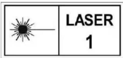
1 Introduction
1.1 Product Introduction
0100 series 100 Mbps Ethernet switches are layer 2 switches, providing five, eight, or sixteen 10/100 Mbps Ethernet ports to upload data via aggregation switches. The devices are reliable, easy to install and maintain, and equipped with rapid switching functions. With multiple access ports, the devices are suitable for small-scale LAN device access.
1.2 Packing List
| Accessory | 0105 Series | 0108 Series | 0116 Series |
| Switch | × 1 | × 1 | × 1 |
| Power Adapter | × 1 | × 1 | - |
| Power Cord | - | - | × 1 |
| L-Shaped Bracket | - | - | × 2 |
| Screw | - | - | × 4 |
| Quick Start Guide | × 1 | × 1 | × 1 |
| Multilingual Quick Start Guide | × 1 | × 1 | × 1 |
1.3 Appearance
Device appearances vary with different models. The actual device prevails.
Front Panel
0105 series switches feature five 10/100 Mbps RJ45 ports.
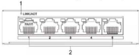
Figure 1-1 0105 Series
Note
The front panel of 0108 series switches is similar to that of 0105 series switches. The only difference is that 0108 series switches feature eight 10/100 Mbps RJ45 ports.
0116 series switches feature sixteen 10/100 Mbps RJ45 ports.
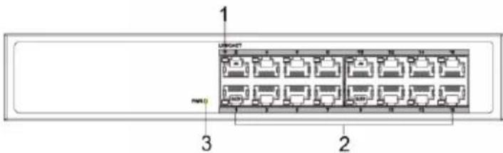
Figure 1-2 0116 Series
Rear Panel
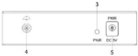
Figure 1-3 0105 Series
Note
The rear panel of 0108 series switches is the same as that of 0105 series switches.
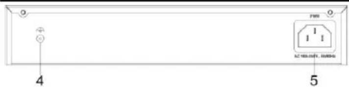
Figure 1-4 0116 Series
Port/Indicator Description
| No. | Indicator/Port | Description |
| 1 | LINK/ACT Indicator | Solid on: The port is connected.Flashing: The port is transmitting data.Unlit: The port is disconnected or connection is abnormal. |
| 2 | 10/100 Mbps RJ45 Port | Used for connection to another device via a network cable. |
| 3 | PWR Indicator | Solid on: The switch is powered on normally.Unlit: No power supply is connected or power supply is abnormal. |
| 4 | Grounding Terminal | Used for connecting to the grounding cable to protect the switch from lightning. |
| 5 | Power Supply | Use the attached power cord to connect the switch to a socket. |
2 Installation
Please select the appropriate installation method according to the actual needs.
Note
If screws are not provided in the package, prepare them yourself.
Before You Start
- Ensure that the desktop, wall, rack, or rail is stable and firm enough.
- Keep the room well-ventilated. Leave at least 10 cm of heat dissipation space around the device.
- Keep at least 1.5 cm vertical distance between two adjacent devices for rack-mounted installation.
2.1 Desktop Installation
Place the device on the desk.
2.2 Wall-Mounted Installation
Steps
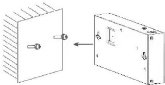
- Check the distance between the two hanging holes on the rear cover of the device.
- Insert two M4 screws into the wall.
Note
- Ensure that the distance between the two screws equals to the distance between the two hanging holes.
-
Set aside at least 4 mm of the screw bodies outside the wall.
-
Align the hanging holes with the screws, and hang the device on the screws.
natural_image
Diagram showing a wall-mounted component being inserted into a rectangular housing, with no visible text or symbols.Figure 2-1 Wall-Mounted Installation
2.3 Rack-Mounted Installation
Steps
- Check the grounding and stability of the rack.
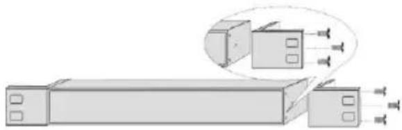
- Use screws to fix the two L-shaped brackets to both sides of the device.
natural_image
Diagram of a mechanical assembly with two blocks and a magnified inset showing internal components (no text or symbols)Figure 2-2 Fix L-Shaped Brackets
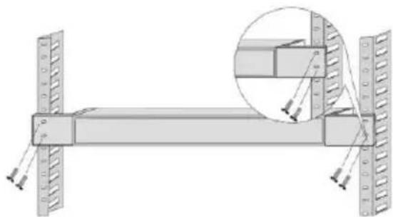
- Place your device against the rack, and fix the brackets to the rack with screws to stably install your device.
natural_image
Mechanical assembly diagram showing a beam supported by vertical supports and a magnified inset of a structural detail (no text or symbols)Figure 2-3 Fix Brackets to Rack
2.4 Rail-Mounted Installation
Steps
- Fix the clip to the device. Insert the end of the DIN rail-mounted unit into the notch under the clip.
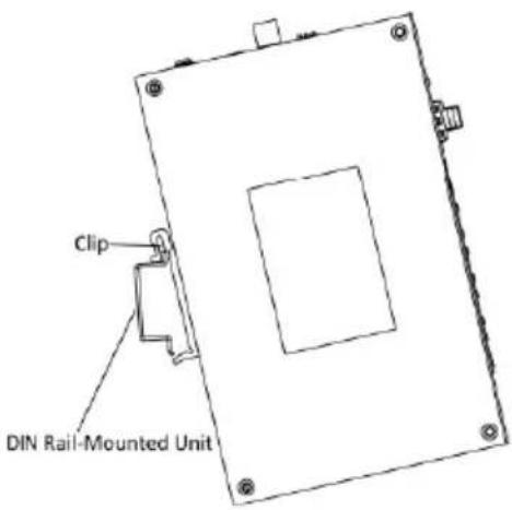
Figure 2-4 Rail-Mounted Installation
- Press the DIN rail-mounted unit in quickly.
3 Grounding
3.1 Connect Grounding Cable
Grounding is used to quickly release overvoltage and overcurrent induced by lightening on the device, and to protect personal safety. Select an appropriate grounding method according to the installation conditions.
Note
The grounding terminal is on the rear panel or side panel of the device. The actual device prevails.
3.1.1 With Grounding Bar
If a grounding bar is available at the installation site, follow the steps below.
Steps
- Connect one end of the grounding cable to the binding post on the grounding bar.
- Connect the other end of the grounding cable to the grounding terminal of the device and tighten the screw.
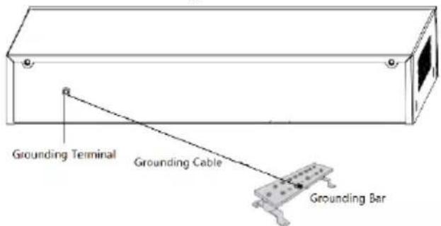
Figure 3-1 Grounding with Grounding Bar
3.1.2 Without Grounding Bar
If there is no grounding bar but the earth is nearby and the grounding body is allowed to be buried, follow the steps below.
Steps
- Bury an angle steel or steel pipe ( ≥ 0.5 m) into the earth.
- Weld one end of the grounding cable to the angle steel or steel pipe and embalm the welding point via electroplating or coating.
- Connect the other end of the grounding cable to the grounding terminal.
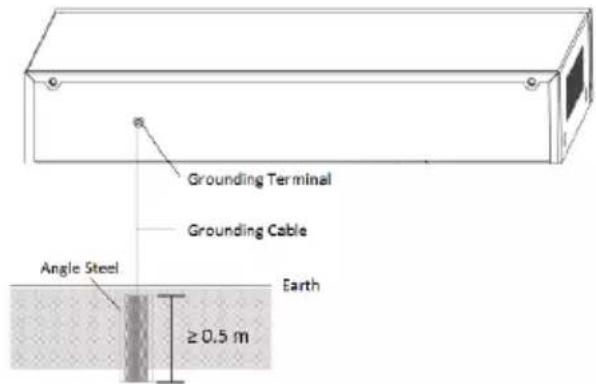
Figure 3-2 Grounding with Angle Steel
3.2 Connect RJ45 Port
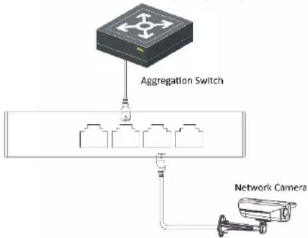
Use a network cable to connect the device to the RJ45 port of a peer device such as network camera, NVR, switch, etc.
flowchart
graph TD
    A["Router"] --> B["Aggregation Switch"]
    B --> C["Network Camera 10"]
Figure 3-3 RJ45 Port Connection
3.3 Connect SFP Optical Module
Connecting an SFP optical module is supported when the device has a fiber optical port or a combo interface.
Note
A combo interface consists of a RJ45 port and a fiber optical port. You can use either the RJ45 port or the fiber optical port of a combo interface, but cannot use them at the same time.
- When connected to a network cable, the combo interface is a RJ45 port.
- When plugged into with an optical module and connected to an optical fiber, the combo interface functions as a fiber optical port.
- When connected to both a network cable and an optical fiber, the combo interface works as a fiber optical port.
Steps

Caution
- Single-Mode optical module needs to be paired for use.
- Do not bend an optical fiber (curvature radius ≥ 10 cm) overly.
-
Do not look directly at an optical fiber connector because the laser generated is harmful to eyes.
-
Connect the two paired SFP optical modules with an optical fiber.
- Hold the SFP optical module from one side, and smoothly plug it into the device along the SFP port slot until the optical module and the device are closely attached.
-
After powering on the device, check the status of the optical port indicator.
-
If the indicator is lit, the link is connected.
-
If the indicator is unlit, the link is disconnected.
-
Check the line, and make sure that the peer device has been enabled.
4 Device Powering-On
Please use the attached power adapter or power cord to power on the device.
Before powering on your device, make sure that:
- The operating power supply is compliant with rated input standard.
- Port cables and grounding cables are correctly connected.
- If there is outdoor cabling, connect a lightning rod and a lightening arrester to the cable.

Caution
Power supply lines and strong current wires cannot be wired together, otherwise PDs or switch ports will be burnt.
- Symbol Conventions
- Safety Instructions
- Danger
- Caution
- Introduction
- Product Introduction
- Packing List
- Appearance
- Front Panel
- Note
- Rear Panel
- Port/Indicator Description
- Installation
- Before You Start
- Desktop Installation
- Wall-Mounted Installation
- Steps
- Rack-Mounted Installation
- Rail-Mounted Installation
- Grounding
- Connect Grounding Cable
- With Grounding Bar
- Without Grounding Bar
- Connect RJ45 Port
- Connect SFP Optical Module
- Device Powering-On
Brand : Hikvision
Model : DS-3E0116R-O
Category : Network switch