
DS-3E3728F-H - Network switch Hikvision - Free user manual and instructions
Find the device manual for free DS-3E3728F-H Hikvision in PDF.


| Product Type | Managed Network Switch |
| Model | DS-3E3728F-H |
| Ports | 24 x 10/100/1000Base-T PoE+ (802.3af/at), 4 x 1000Base-X SFP |
| PoE Budget | 370 W |
| Switching Capacity | 56 Gbps |
| Forwarding Rate | 41.67 Mpps |
| MAC Address Table | 8K |
| Dimensions (W x D x H) | 440 x 320 x 44 mm (17.32 x 12.6 x 1.73 in) |
| Weight | 4.2 kg (9.26 lb) |
| Power Supply | AC 100-240V, 50/60 Hz |
| Power Consumption | ≤ 450 W (with PoE) |
| Operating Temperature | 0°C to 45°C (32°F to 113°F) |
| Storage Temperature | -40°C to 70°C (-40°F to 158°F) |
| Humidity | 5% to 95% non-condensing |
| Management | Web UI, SNMP v1/v2c/v3, CLI |
| VLAN Support | 802.1Q, up to 4K VLANs |
| QoS | 8 priority queues |
| Security | Port security, ACL, 802.1X |
| Cleaning | Use a dry, soft cloth. Avoid liquids. |
| Spare Parts & Repairability | Contact Hikvision support; not user-serviceable. |
Frequently Asked Questions - DS-3E3728F-H Hikvision
User questions about DS-3E3728F-H Hikvision
0 question about this device. Answer the ones you know or ask your own.
Ask a new question about this device
Download the instructions for your Network switch in PDF format for free! Find your manual DS-3E3728F-H - Hikvision and take your electronic device back in hand. On this page are published all the documents necessary for the use of your device. DS-3E3728F-H by Hikvision.
USER MANUAL DS-3E3728F-H Hikvision
The installation tools are not provided with the switch. Prepare them yourself as required.





Flathead screwdriver
Phillips screwdriver
Needle-nose pliers
ESD wrist strap
Marker
Installation accessories


Cage nutGrounding cable M6 screw
M4 countersunk-head screw
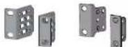
(Type A) (Type B)
Mounting brackets Rubber feet Grounding screw


Cable tie

The applicable installation accessories vary by switch model. Some accessories are not provided with the switch. The packing list describes the accessories provided with the switch.
A Wear an ESD wrist strap, and make sure the wrist strap makes good skin contact and is reliably grounded.
Mounting the switch in a rack
The applicable mounting brackets vary by switch model. Some switch models provide two installation positions on the two sides for mounting brackets: one at the port side and one at the power module side. Select an installation position for the mounting brackets as required.
Four screws are required to attach a Type A mounting bracket. Two screws are required to attach a Type B mounting bracket.
1 Attaching mounting brackets to the switch
Type A mounting bracket
Type A mounting bracket
Type B mounting bracket
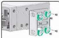
Installation at the port side
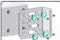
Installation at the power module side
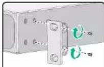
Installation at the port side
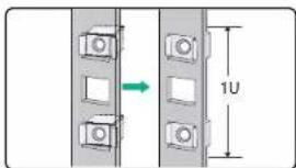
2 Attach cage nuts to the rack posts
Mount the switch in the rack
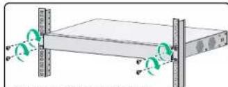
natural_image
Diagram of a server rack with two vertical connectors and green circular indicators on one side (no text or symbols)Example: Installation at the port side
Mounting the switch on a workbench
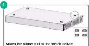
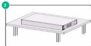
natural_image
Simple line drawing of a rectangular electronic device on a flat table (no text or symbols)Grounding the switch
Correctly connecting the switch grounding cable is crucial to lightning protection and EMI protection. Use the grounding cable provided with the chassis to ground the switch.
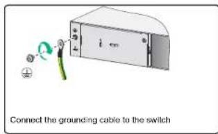
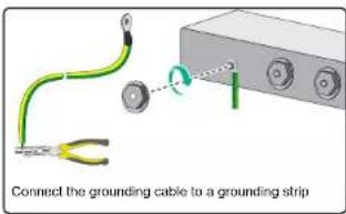
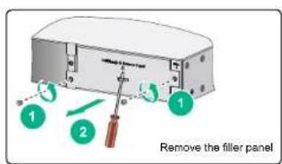
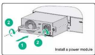
Installing and removing a power module
This section is applicable only to switch models that use removable power modules.
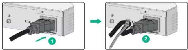
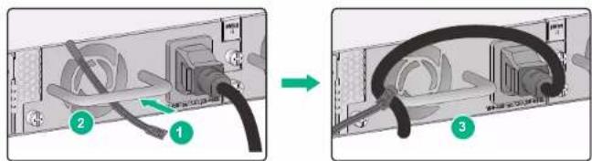
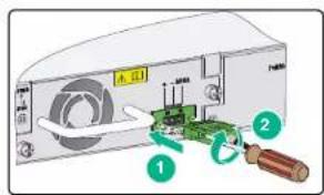
Connecting the power cord
Before connecting the power cord, connect the grounding cable and make sure the switch is reliably grounded. To avoid bodily injury, connect the power cord first to the switch and then to the power supply system.
1 Connecting the power cord for an AC power module.
Method 1
Method 2
2 Connecting the power cord for a DC power module.
Brand : Hikvision
Model : DS-3E3728F-H
Category : Network switch