
DS-3E1310P-SI - Network switch Hikvision - Free user manual and instructions
Find the device manual for free DS-3E1310P-SI Hikvision in PDF.


| Product Type | Network switch |
| Model | DS-3E1310P-SI |
| Brand | Hikvision |
| Category | Unmanaged PoE switch |
| Ports | 8 x 10/100 Mbps PoE ports + 2 x 10/100 Mbps uplink ports |
| PoE Standard | IEEE 802.3af/at |
| PoE Power Budget | 120 W |
| Switching Capacity | 2.0 Gbps |
| MAC Address Table | 2K entries |
| Enclosure | Metal case |
| Dimensions (W x D x H) | 200 mm x 120 mm x 30 mm |
| Weight | 0.7 kg |
| Power Input | 100-240 V AC, 50-60 Hz |
| Power Consumption | ≤ 130 W (with full PoE load) |
| Operating Temperature | 0°C to 40°C |
| Humidity | 5% to 95% (non-condensing) |
| LED Indicators | Power, Link/Act, PoE |
| Mounting | Desktop or wall mount (bracket included) |
| Fanless | Yes |
| Warranty | 3 years limited warranty |
Frequently Asked Questions - DS-3E1310P-SI Hikvision
User questions about DS-3E1310P-SI Hikvision
0 question about this device. Answer the ones you know or ask your own.
Ask a new question about this device
Download the instructions for your Network switch in PDF format for free! Find your manual DS-3E1310P-SI - Hikvision and take your electronic device back in hand. On this page are published all the documents necessary for the use of your device. DS-3E1310P-SI by Hikvision.
USER MANUAL DS-3E1310P-SI Hikvision
©2020 Hangzhou Hikvision Digital Technology Co., Ltd. All rights reserved.
About this Manual
The Manual includes instructions for using and managing the Product. Pictures, charts, images and all other information hereinafter are for description and explanation only. The information contained in the Manual is subject to change, without notice, due to firmware updates or other reasons. Please find the latest version of this Manual at the Hikvision website (https://www.hikvision.com/).
Please use this Manual with the guidance and assistance of professionals trained in supporting the Product.
Trademarks
HIKVISION and other Hikvision's trademarks and logos are the properties of Hikvision in various jurisdictions.
Other trademarks and logos mentioned are the properties of their respective owners.
Disclaimer
TO THE MAXIMUM EXTENT PERMITTED BY APPLICABLE LAW, THIS MANUAL AND THE PRODUCT DESCRIBED, WITH ITS HARDWARE, SOFTWARE AND FIRMWARE, ARE PROVIDED "AS IS" AND "WITH ALL FAULTS AND ERRORS". HIKVISION MAKES NO WARRANTIES, EXPRESS OR IMPLIED, INCLUDING WITHOUT LIMITATION, MERCHANTABILITY, SATISFACTORY QUALITY, OR FITNESS FOR A PARTICULAR PURPOSE. THE USE OF THE PRODUCT BY YOU IS AT YOUR OWN RISK. IN NO EVENT WILL HIKVISION BE LIABLE TO YOU FOR ANY SPECIAL, CONSEQUENTIAL, INCIDENTAL, OR INDIRECT DAMAGES, INCLUDING, AMONG OTHERS, DAMAGES FOR LOSS OF BUSINESS PROFITS, BUSINESS INTERRUPTION, OR LOSS OF DATA, CORRUPTION OF SYSTEMS, OR LOSS OF DOCUMENTATION, WHETHER BASED ON BREACH OF CONTRACT, TORT (INCLUDING NEGLIGENCE), PRODUCT LIABILITY, OR OTHERWISE, IN CONNECTION WITH THE USE OF THE PRODUCT, EVEN IF HIKVISION HAS BEEN ADVISED OF THE POSSIBILITY OF SUCH DAMAGES OR LOSS.
YOU ACKNOWLEDGE THAT THE NATURE OF THE INTERNET PROVIDES FOR INHERENT SECURITY RISKS, AND HIKVISION SHALL NOT TAKE ANY RESPONSIBILITIES FOR ABNORMAL OPERATION, PRIVACY LEAKAGE OR OTHER DAMAGES RESULTING FROM CYBER-ATTACK, HACKER ATTACK, VIRUS INFECTION, OR OTHER INTERNET SECURITY RISKS; HOWEVER, HIKVISION WILL PROVIDE TIMELY TECHNICAL SUPPORT IF REQUIRED.
YOU AGREE TO USE THIS PRODUCT IN COMPLIANCE WITH ALL APPLICABLE LAWS, AND YOU ARE SOLELY RESPONSIBLE FOR ENSURING THAT YOUR USE CONFORMS TO THE APPLICABLE LAW. ESPECIALLY, YOU ARE RESPONSIBLE, FOR USING THIS PRODUCT IN A MANNER THAT DOES NOT INFRINGE ON THE RIGHTS OF THIRD PARTIES, INCLUDING WITHOUT LIMITATION, RIGHTS OF PUBLICITY, INTELLECTUAL PROPERTY RIGHTS, OR DATA PROTECTION AND OTHER PRIVACY RIGHTS. YOU SHALL NOT USE THIS PRODUCT FOR ANY PROHIBITED END-USES, INCLUDING THE DEVELOPMENT OR PRODUCTION OF WEAPONS OF MASS DESTRUCTION, THE DEVELOPMENT OR
PRODUCTION OF CHEMICAL OR BIOLOGICAL WEAPONS, ANY ACTIVITIES IN THE CONTEXT RELATED TO ANY NUCLEAR EXPLOSIVE OR UNSAFE NUCLEAR FUEL-CYCLE, OR IN SUPPORT OF HUMAN RIGHTS ABUSES.
IN THE EVENT OF ANY CONFLICTS BETWEEN THIS MANUAL AND THE APPLICABLE LAW, THE LATER PREVAILS.
Regulatory Information
FCC Information
Please take attention that changes or modification not expressly approved by the party responsible for compliance could void the user's authority to operate the equipment.
FCC compliance: This equipment has been tested and found to comply with the limits for a Class A digital device, pursuant to part 15 of the FCC Rules. These limits are designed to provide reasonable protection against harmful interference when the equipment is operated in a commercial environment. This equipment generates, uses, and can radiate radio frequency energy and, if not installed and used in accordance with the instruction manual, may cause harmful interference to radio communications. Operation of this equipment in a residential area is likely to cause harmful interference in which case the user will be required to correct the interference at his own expense.
FCC Conditions
This device complies with part 15 of the FCC Rules. Operation is subject to the following two conditions:
-
This device may not cause harmful interference.
-
This device must accept any interference received, including interference that may cause undesired operation.
EU Conformity Statement

This product and - if applicable - the supplied accessories too are marked with "CE" and comply therefore with the applicable harmonized European standards listed under the EMC Directive 2014/30/EU, the RoHS Directive 2011/65/EU.

2012/19/EU (WEEE directive): Products marked with this symbol cannot be disposed of as unsorted municipal waste in the European Union. For proper recycling, return this product to your local supplier upon the purchase of equivalent new equipment, or dispose of it at designated collection points. For more information see: http://www.recyclethis.info.

2006/66/EC (battery directive): This product contains a battery that cannot be disposed of as unsorted municipal waste in the European Union. See the product documentation for specific battery information. The battery is marked with this symbol, which may include lettering to indicate cadmium (Cd), lead (Pb), or mercury (Hg). For proper recycling, return the battery to your supplier or to a designated collection point. For more information see: http://www.recyclethis.info .
Industry Canada ICES-003 Compliance
This device meets the CAN ICES-3 (A)/NMB-3(A) standards requirements.
Preface
Applicable Models
This manual is applicable to DS-3E13XXP-SI series switches.
About the Default
- Default administrator account: admin.
- Default IP address: 192.168.1.64.
Symbol Conventions
The symbols that may be found in this document are defined as follows.
| Symbol Description | |
 Danger Danger | Indicates a hazardous situation which, if not avoided, will or could result in death or serious injury. |
 Caution Caution | Indicates a potentially hazardous situation which, if not avoided, could result in equipment damage, data loss, performance degradation, or unexpected results. |
 Note Note | Provides additional information to emphasize or supplement important points of the main text. |
Safety Instruction

Danger
- This is a class A product and may cause radio interference in which case the user may be required to take adequate measures.
- Ensure that your devices powered via the PoE port have their shells protected and fire-proofed, because the switches are not compliant with the Limited Power Source (LPS) standard.
- In the use of the product, you must be in strict compliance with the electrical safety regulations of the nation and region.
- The socket-outlet shall be installed near the device and shall be easily accessible.
-
The device must be connected to an earthed mains socket-outlet.
• Install the device according to the instructions in this manual. -
12 indicates hazardous live and the external wiring connected to the terminals requires installation by an instructed person.
- Keep body parts away from fan blades. Disconnect the power source during servicing.
- Never place the device in an unstable location. The device may fall, causing serious personal injury or death.
- This device is not suitable for use in locations where children are likely to be present.
- CAUTION: Risk of explosion if the battery is replaced by an incorrect type.
- Improper replacement of the battery with an incorrect type may defeat a safeguard (for example, in the case of some lithium battery types).
- Do not dispose of the battery into fire or a hot oven, or mechanically crush or cut the battery, which may result in an explosion.
- Do not leave the battery in an extremely high temperature surrounding environment, which may result in an explosion or the leakage of flammable liquid or gas.
- Do not subject the battery to extremely low air pressure, which may result in an explosion or the leakage of flammable liquid or gas. Dispose of used batteries according to the instructions.

Caution
- CAUTION: Double pole/Neutral fusing. After operation of the fuse, parts of the device that remain energized might represent a hazard during servicing.
- The device has been designed, when required, modified for connection to an IT power distribution system.
- This device is suitable for mounting on concrete or other non-combustible surface only.
- The ventilation should not be impeded by covering the ventilation openings with items, such as newspapers, table-cloths, curtains, etc. The openings shall never be blocked by placing the device on a bed, sofa, rug or other similar surface.
- No naked flame sources, such as lighted candles, should be placed on the device.
- The device shall not be exposed to dripping or splashing and that no objects filled with liquids, such as vases, shall be placed on the device.
- Burned fingers when handling the cover area of the device. Wait one-half hour after switching off before handling the parts.
• CLASS 1 LASER PRODUCT

Contents
Chapter 1 Product Introduction ...... 1
Chapter 2 Activation and Login ...... 2
Chapter 3 Device Management .... 4
Chapter 4 Switch Configuration ...... 7
4.1 Port Configuration 7
4.1.1 Attribute Configuration 7
4.1.2 Configure Port Mirroring 8
4.1.3 Long-Range Mode Configuration 8
4.1.4 Configure Port Isolation 9
4.2 Link Aggregation Configuration 10
4.3 VLAN Configuration 11
4.3.1 Add a VLAN 11
4.3.2 Configure a Port 12
4.4 QoS Configuration 14
4.5 SNMP Configuration 16
4.5.1 SNMP Proxy Settings 17
4.5.2 SNMP Trap Settings 17
4.6 STP Configuration 18
4.6.1 Global Configuration 18
4.6.2 STP Port Configuration 20
4.6.3 STP Status View 22
4.7 PoE Management 22
Chapter 5 System Management ...... 24
5.1 Time Sync 24
5.2 Device Operation 24
5.3 Configuration File Export 25
5.4 Configuration File Import 26
5.5 Device Upgrade 26
5.6 Log Management 26
5.7 Network Diagnostics 27
5.8 User Management 28
5.9 Security Management 29
5.10 Configure Network 29
Chapter 1 Product Introduction
DS-3E13XXP-SI series switches (hereinafter referred to as "the device") are layer 2 PoE switches, providing advanced PoE power supply technology on the basis of high-performance access. The switches support client management, network topology management, linkaggregation, port management and so on. The switches are suitable for small-scale LAN device access.
Chapter 2 Activation and Login
For the first time usage, you must activate the switch and configure the password.
Before You Start
The computer and the switch are on the same network segment.
Steps

Take DS-3E1510P as an example. All figures in this manual are for illustration purpose only.
- Enter the default IP 192.168.1.64 in the browser address bar.
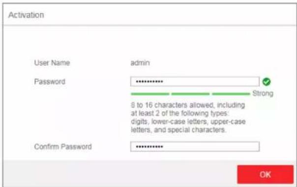
Figure 2-1 Activation

You are recommended to use the newest version of the following browsers: IE 10+, Edge, and Chrome 31+.
-
Configure the password and confirm it.
-
Click OK.
Go to the login page.
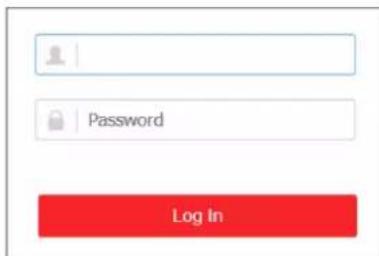
Figure 2-2 Login
-
Enter the User Name and Password, and click Log In.
-
Optional: Change the network configuration.
1) Go to System Management → Network Configuration.
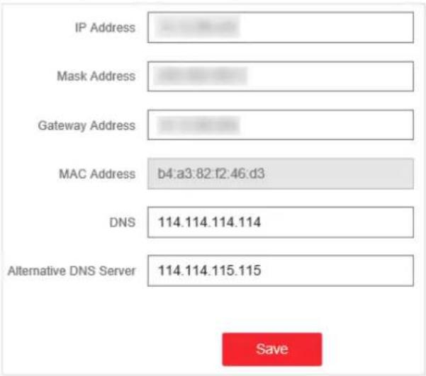
Figure 2-3 Network Configuration
2) Change the IP address, mask address, the gateway address, DNS and alternative DNS as needed. You can log in to the switch with the new IP address next time.
i Note
You are recommended to change the network configuration to better manage the switch.
Chapter 3 Device Management
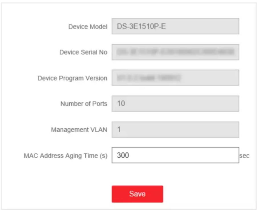
After logging in to the Web, you can go to Device Status to view the device status, including the device information, working status, port status, port statistics, and PoE status.
Device Information
bar
| Category | Value | |---|---| | Device Model | DS-3E1510P-E | | Device Serial No | 0 sec | | Device Program Version | 0 sec | | Number of Ports | 10 | | Management VLAN | 1 | | MAC Address Aging Time (s) | 300 sec | SaveFigure 3-1 Device Information
- Management VLAN: The management VLAN is VLAN 1 by default that cannot be edited.
- MAC Address Aging Time: Aging time for MAC address table entries. The default is 300 seconds that cannot be edited.
Working Status
pie
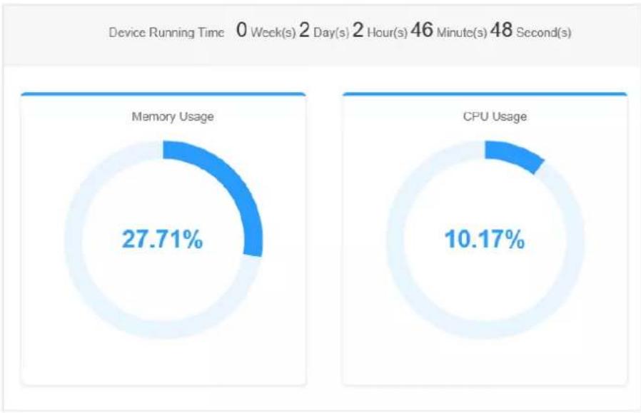
| Category | Percentage (%) | | :--- | :--- | | Memory Usage | 27.71 | | CPU Usage | 10.17 | Device Running Time: 0 Week(s) 2 Day(s) 2 Hour(s) 46 Minute(s) 48 Second(s)Figure 3-2 Working Status
View the device running time, memory usage, and CPU usage.
Port Status
| Port Name | Connection Status | Rate | Duplex | Flow Control |
| Ge1 | Disconnected | - | - | - |
| Ge2 | Connected | 1000M | Full-Duplex | Off |
| Ge3 | Disconnected | - | - | - |
| Ge4 | Connected | 1000M | Full-Duplex | Off |
| Ge5 | Disconnected | - | - | - |
| Ge6 | Disconnected | - | - | - |
| Ge7 | Disconnected | - | - | - |
| Ge8 | Connected | 1000M | Full-Duplex | On |
| Ge9 | Connected | 1000M | Full-Duplex | On |
| Ge10 | Disconnected | - | - | - |
Figure 3-3 Port Status
View the connection status, rate, duplex, and flow control of all ports.
Port Statistics
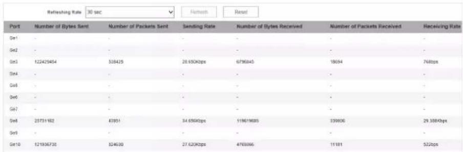
Figure 3-4 Port Statistics
- Refreshing Rate: 10 sec, 30 sec, 60 sec, and Manually Refresh is available.
- Refresh: When you choose Manually Refresh, you can click Refresh to refresh the statistics.
- Reset: You can click Reset to clear all the statistics.
PoE Status
| Port Name | Output Power (W) |
| Ge1 | - |
| Ge2 | - |
| Ge3 | 2.0 |
| Ge4 | 0.0 |
| Ge5 | 0.0 |
| Ge6 | 0.0 |
| Ge7 | 0.0 |
| Ge8 | 0.0 |
Figure 3-5 PoE Status
View the complete appliance PoE status and the output power of each PoE port.
Chapter 4 Switch Configuration
4.1 Port Configuration
4.1.1 Attribute Configuration
The basic parameters can influence the working status of ports. Configure the parameters according to the actual situation.
Steps
- Go to Switch Configuration → Basic Configuration → Port Configuration → Attribute Configuration.
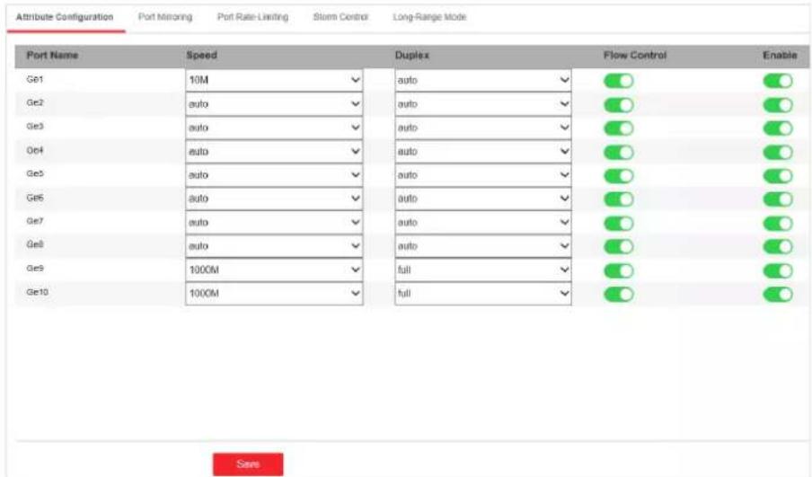
Figure 4-1 Port Attribute Configuration
- Configure the parameters.
Speed
The speed of data transmission of the port.
- PoE port: The default is auto.
- SFP fiber optical port: The default is auto that cannot be edited.
Duplex
The duplex mode of the port.
- PoE port: The default is auto that cannot be edited.
- SFP fiber optical port: The default is auto that cannot be edited.
Flow Control
Enabling the flow control can prevent data loss in data transmission.
Enable
Enable or disable the port link.
- Click Save to complete the configuration.
4.1.2 Configure Port Mirroring
Port mirroring monitors network traffic by sending copies of all incoming and outgoing packets from one port to a mirroring port.
Steps
- Go to Switch Configuration → Basic Configuration → Port Configuration → Port Mirroring.
- Check Enable of Port Mirroring.
- Select one port as Mirror Port, which monitors and analyzes the packets from mirror source ports.
- Select Mirror Direction.
Disable Mirror
The port is not under surveillance.
Inbound
The data received by the mirror source port is under surveillance.
Outbound
The data sent from the mirror source port is under surveillance.
Inbound and Outbound
Both received and sent data of the mirror source port are under surveillance.
- Switch on Set as Mirror Source if you want to select certain ports from the list as mirror source that is under surveillance.

Note
You can set one or more ports as the mirror source.
- Click Save to complete the port mirroring configuration.
4.1.3 Long-Range Mode Configuration
When long-range mode is enabled, the transmission distance of the port can reach 300 meters, and the rate is 10 Mbps.
Steps
- Go to Switch Configuration → Basic Configuration → Port Configuration → Long-Range Mode.
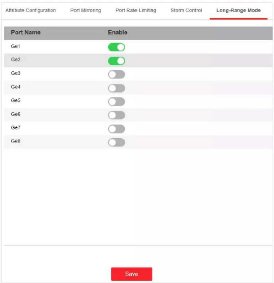
Figure 4-2 Long-Range Mode Configuration
- Check Enable of the port.
- Click Save to complete the configuration.
4.1.4 Configure Port Isolation
Set ports to different VLAN in order to isolate different packets on Layer 2. Ports in the same isolation group cannot communicate with each other while can communicate with the ports of different group.
Steps
- Go to Switch Configuration → Basic Configuration → Port Configuration → Port Isolation.
- Select the ports to isolation group.
- Click Save.
4.2 Link Aggregation Configuration
Link aggregation is used to aggregate physical ports to create a logical channel. The advantages of link aggregation are higher transmission speed with wider bandwidth.
Steps
- Go to Switch Configuration → Basic Configuration → Link Aggregation → Load Balancing Configuration to configure Load Balancing Mode.

Figure 4-3 Load Balancing
Source and Destination MAC
Load balancing is performed based on source and destination MAC addresses on all the packets.
- Add a link aggregation group in Aggregation Group Configuration.
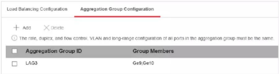
Figure 4-4 Link Aggregation Group
1) Click Add.
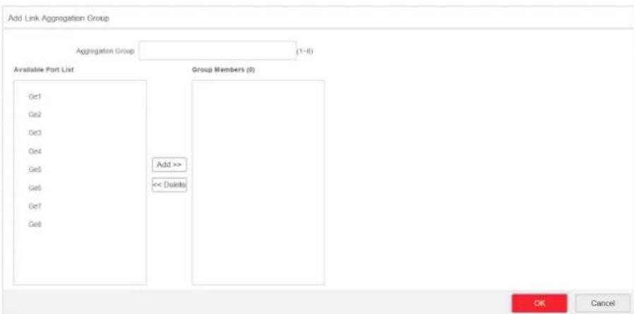
Figure 4-5 Add a Link Aggregation Group
2) Enter the group number in the Aggregation Group field. The range is from 1 to 8.
3) Move the ports that are to be assigned to the group from the Available Port List to the Group Members list.

- You can delete the ports from the Group Members by clicking Delete.
- The rate, duplex, flow control, VLAN, and long-range configuration of all ports in one aggregation group must be the same.
4) Click OK to add a link aggregation group.
4.3 VLAN Configuration
A Virtual Local Area Network (VLAN) is a group of devices located on different LAN segments that are configured to communicate as if they were attached to the same wire. LANs are based on logical instead of physical connections, which is flexible for device connection.
4.3.1 Add a VLAN
Steps
- Go to Switch Configuration → Basic Configuration → VLAN → 802.1Q VLAN.
- Click Add.
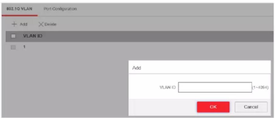
Figure 4-6 Add a VLAN
3. Enter a VLAN ID.

Note
- A maximum of 128 VLANs are supported.
• The range is from 1 to 4094.
4. Optional: You can also delete a VLAN by clicking Delete.

Note
You cannot delete the VLAN 1, because VLAN 1 is the Management VLAN.
4.3.2 Configure a Port
Steps
- Select a port to configure on the Port Configuration page.
| 802.1Q VLAN Port Configuration | |||
| Edit | |||
| Port Name | VLAN Type | PVID | Accessible VLAN |
| Ge1 | ACCESS | 1 | 1 |
| Ge2 | ACCESS | 1 | 1 |
| Ge3 | ACCESS | 1 | 1 |
| Ge4 | ACCESS | 1 | 1 |
| Ge5 | ACCESS | 1 | 1 |
| Ge6 | ACCESS | 1 | 1 |
| Ge7 | ACCESS | 1 | 1 |
| Ge8 | ACCESS | 1 | 1 |
| Ge9 | ACCESS | 1 | 1 |
| Ge10 | ACCESS | 1 | 1 |
Figure 4-7 VLAN Port Configuration
- Click Edit.
- Configure the port VLAN.
- Access Port
- An access port transports traffic to and from only the specified VLAN, usually the default VLAN, VLAN 1.
- Select Port VLAN Type as ACCESS, and select the PVID.
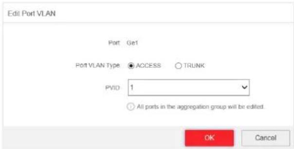
Figure 4-8 Edit an Access Port VLAN

All ports in the same aggregation group will be edited automatically at the same time.
- Trunk Port
- A trunk port is a port that is assigned to carry traffic for all the VLANs.
- Select Port VLAN Type as TRUNK, select the PVID and enter the VLAN that are allowed to be accessed.
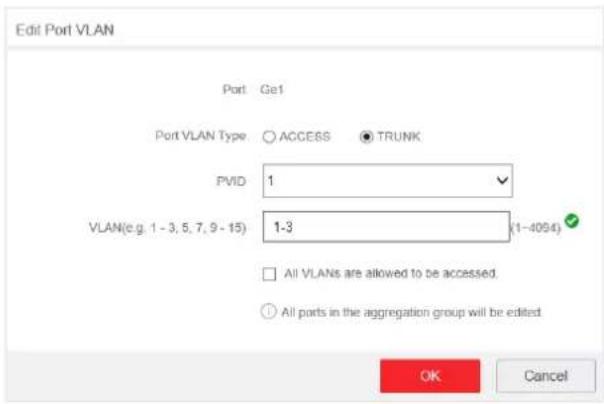
Figure 4-9 Edit a Trunk Port VLAN
iNote
- All ports in the same aggregation group will be edited automatically at the same time.
-
You can check All VLANS are allowed to be accessed. to assign the port to all the VLANs.
-
Click OK.
- Click Save to save the configuration.
4.4 QoS Configuration
Quality of Service (QoS) includes the transmission bandwidth, delay, packet loss rate and etc. Increasing network bandwidth, decreasing network delay, and reducing packet losses can improve QoS in network service. You can configure the scheduling mode and port priority of QoS.
Steps
- Go to Switch Configuration → Basic Configuration → QoS → Scheduling Mode to select a scheduling type.
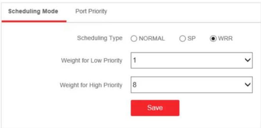
Figure 4-10 Scheduling Mode
NORMAL
First In First Out (FIFO) mode. Transmit the message coming in first. QoS is not enabled.
SP
Strict Priority mode. Transmit the message according to the actual priority configuration.
WRR
Weighted Round Robin mode. Transmit the message according to the respective weight for low priority and high priority.
- Configure the port priority in Port Priority.
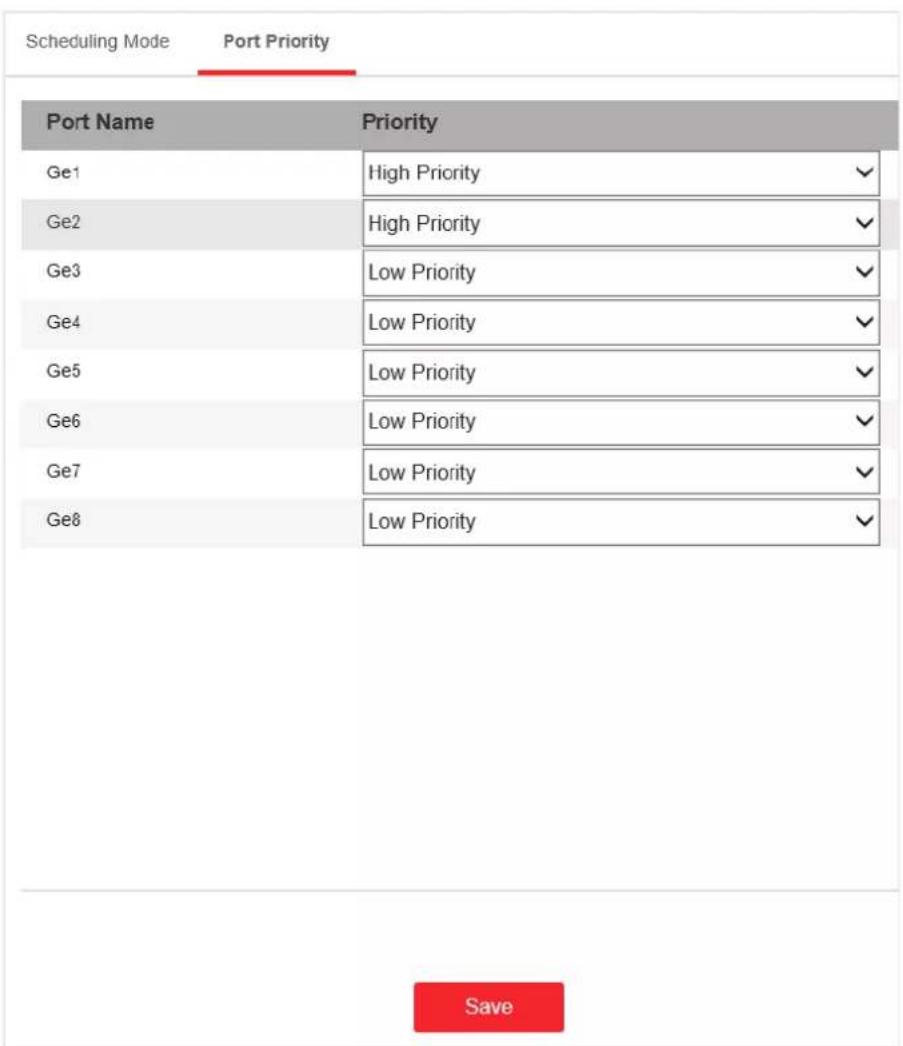
Figure 4-11 Port Priority
- Click Save to complete the configuration.
4.5 SNMP Configuration
Simple Network Management Protocol (SNMP) is a widely used application-layer communication protocol for monitoring network performance. SNMP network is composed of the Network Management System (NMS) and the Agent. NMS is the SNMP manager, and Agent sends Traps to NMS.
4.5.1 SNMP Proxy Settings
Steps
- Go to Switch Configuration → L2 Configuration → SNMP Configuration → SNMP Proxy Settings to configure SNMP proxy.
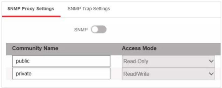
Figure 4-12 Proxy Settings
1) Enable SNMP.
2) Define the Community Name.
Community Name
The community name is an authentication mechanism, similar to a password, which is used to limit the data transmission between NMS and Agent.
- Read-Only Community Name: The Community name accessible to NMS with read permission. The default is public.
- Read/Write Community Name: The Community name accessible to NMS with read and write permission. The default is private.
3) Click Save.
4.5.2 SNMP Trap Settings
Steps
- Enable Trap on the SNMP Trap Settings page.
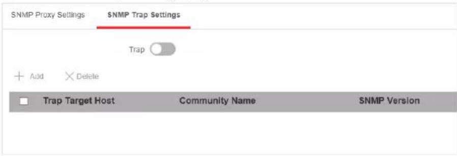
Figure 4-13 Trap Settings
- Click Add to add a trap.
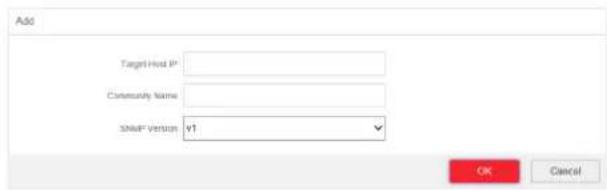
Figure 4-14 Add a Trap
Table 4-1 Parameters of a Trap
| Parameter Description | |
| Target Host IP The IP address of NMS. | It cannot be the broadcast or multicast address. |
| Community Name The password used for authentication. Up to 32 bytes can be set. | |
SNMP Version The Agent supports SNMP Version 1 (SNMPv1) and SNMP Version 2c (SNMPv2c). The prerequisite of successful connection between NMS and Agent is that the SNMP version of NMS and Agent must be the same. The prerequisite of successful connection between NMS and Agent is that the SNMP version of NMS and Agent must be the same. | |
- Click OK.
- Click Save to add a trap.
- Optional: You can check the trap and click Delete to delete a trap.
4.6 STP Configuration
Spanning-Tree Protocol (STP) is a Layer 2 link management protocol that provides path redundancy while preventing loops in the network. The STP uses a spanning-tree algorithm to select one switch as the root of a spanning tree. STP determines the topology by transmitting Bridge Protocol Data Unit (BPDU) packets between devices. Spanning-tree operation creates a stable network.
4.6.1 Global Configuration
Steps
- Go to Switch Configuration → L2 Configuration → STP Configuration → Global Configuration.
- Check Enable STP.
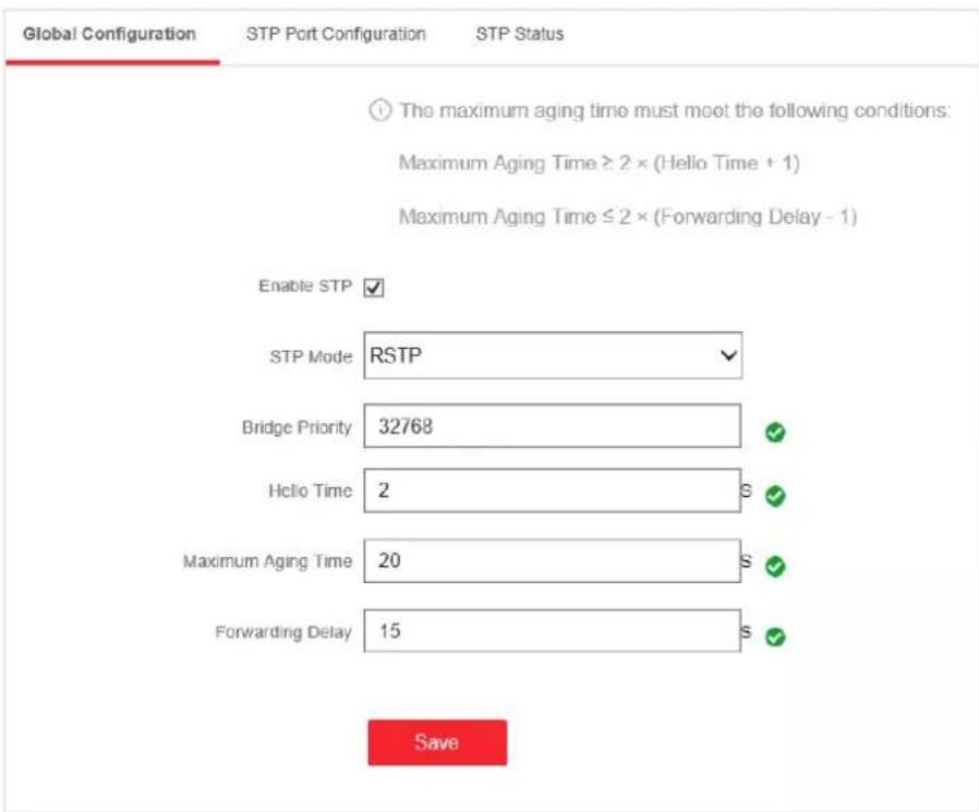
Figure 4-15 Global Configuration
- Configure the parameters.
Table 4-2 Parameters of STP
| Parameter Description | |
| STP Mode • STP: Spanning-tree protocol. | • RSTP: Rapid spanning-tree protocol. RSTP provides faster spanning tree convergence after a topology change. |
| Bridge Priority The lower the number is, | the higher the priority is.The range is from 0 to 61,440 seconds, in increments of 4096; the default is 32,768. Valid values are 0, 4096, 12288, 16384 ... and 61440.A switch with higher bridge priority is more likely to become a root bridge. |
| Hello Time The time between each BPD | U that is sent on a port,which is used for port link diagnosis. The range is from 1 to 10 seconds. The default is 2 seconds. |
| Maximum Aging Time The maximum length of time that passes before abridge port saves its configuration BPDU information. | |
| The range is from 6 to 40 seconds. The default is 20 seconds.NoteThe maximum aging time must meet the following conditions:Maximum Aging Time ≥ (Hello Time + 1)Maximum Aging Time ≤ (Forwarding Delay - 1) | |
| Forwarding Delay The time interval that | is spent in the listening and learning state when the topology changes. The range is from 4 to 30 seconds. The default is 15 seconds. |
- Click Save.
4.6.2 STP Port Configuration
If a loop occurs, you can set port priority so that the spanning tree can select the port with the highest priority to forward data.
Steps
- The port is enabled by default on the STP Port Configuration page.
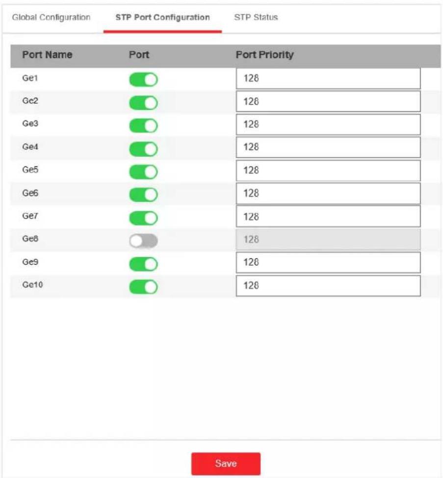
bar
| Port Name | Port | Port Priority | | :--- | :--- | :--- | | Ge1 | [O] | 128 | | Ge2 | [O] | 126 | | Ge3 | [O] | 128 | | Ge4 | [O] | 128 | | Ge5 | [O] | 128 | | Ge6 | [O] | 128 | | Ge7 | [O] | 128 | | Ge8 | [O] | 128 | | Ge9 | [O] | 126 | | Ge10 | [O] | 128 | SaveFigure 4-16 Port Priority
2. Configure the Port Priority.
Port Priority
- The lower the number is, the higher the priority is, the more probably the port becomes the root port.
- The range is from 0 to 240, in increments of 16; the default is 128. Valid values are 0, 16, 32, 48, 64, 80, 96, 112, 128, 144, 160, 176, 192, 208, 224, and 240.

Note
If the priority of the port is the same, spanning tree uses the port ID to select a port as the root port.
3. Click Save.
4.6.3 STP Status View
You can check the global status of STP settings and the status of each port.
Go to Switch Configuration → L2 Configuration → STP Configuration → STP Status.
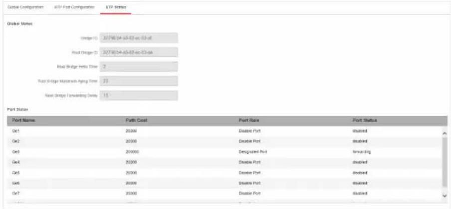
Figure 4-17 STP Status
4.7 PoE Management
PoE Settings
bar
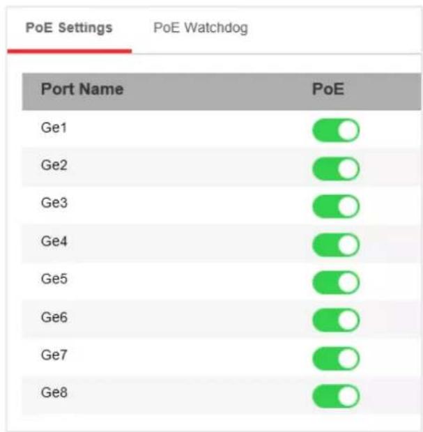
| Port Name | PoE | | :--- | :--- | | Ge1 | ○ | | Ge2 | ○ | | Ge3 | ○ | | Ge4 | ○ | | Ge5 | ○ | | Ge6 | ○ | | Ge7 | ○ | | Ge8 | ○ |Figure 4-18 PoE Settings
You can enable PoE to supply power for the powered devices (PDs).

Note
Enabling or disabling PoE has no influences on data transmission of the port.
PoE Watchdog
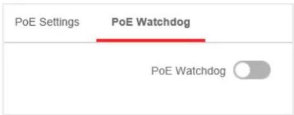
Figure 4-19 PoE Watchdog
You can enable PoE watchdog to auto-detect and restart cameras that do not respond.
Chapter 5 System Management
5.1 Time Sync
Steps
- Go to System Settings → Time Settings. You can view the Device Time.
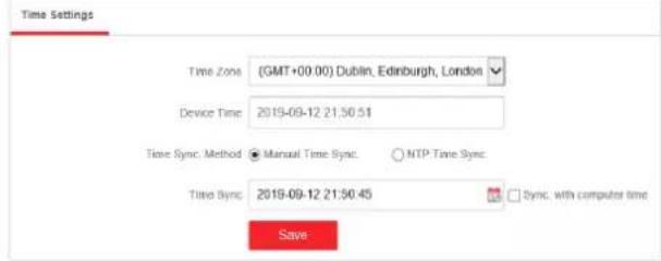
Figure 5-1 Time Settings
- Select Time Zone.
- Select Time Sync. Method
- Set time synchronization mode.
- Manual Time Sync.: Click 📄 or check Sync. with computer time to synchronize the device time.

Figure 5-2 Manual Sync
- NTP Time Sync.: Enter the NTP Server Address, and set the time sync. interval.
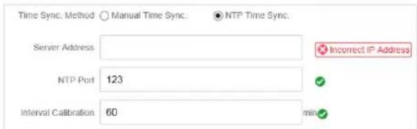
Figure 5-3 NTP Sync
- Click Save.
5.2 Device Operation
When the switch malfunctions or fails to work properly, you can go to System Management → System Maintenance → Device Operation to restart or restore the switch.

Figure 5-4 Device Operation
i Note
Enter the login page automatically after you restart or restore the switch.
Restart
Click Restart to remotely restart the switch.
Restore
- Simply Restore: Except network configuration and user parameters, all of the other parameters are restored to the default settings.
- Completely Restore: Completely restore the parameters to default settings.
Caution
Parameters cannot be recovered after being restoring to default settings.
5.3 Configuration File Export
You can export the configuration file for local backup.
Steps
- Go to System Management → System Maintenance → Export & Import.
- Click Export.
- Set a password for the exported configuration file.
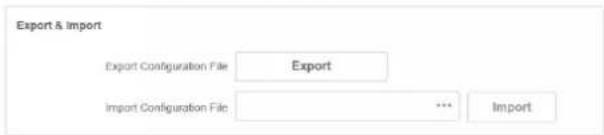
Figure 5-5 Export Configuration file
i Note
Please remember the password, because you need to enter the password when importing the configuration files.
4. Click OK.
5.4 Configuration File Import
You can import the configuration file to configure the system easily.
Steps
- Go to System Management → System Maintenance → Export & Import.
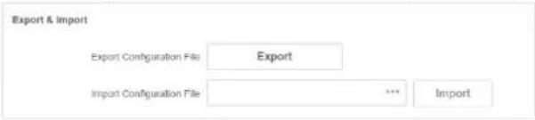
Figure 5-6 Export Configuration file
- Click to select the configuration file.
- Click Import.
The device will restart automatically to enter the login page when the configuration file is imported.
5.5 Device Upgrade
You can upload the upgrade file to upgrade your switch.
Steps
- Go to System Management → System Maintenance → Device Upgrade

Figure 5-7 Upgrade
- Click to select an upgrade patch.
- Click Upgrade.

Note
If upgrading failed or the device cannot function, please contact our technical support engineers.
Result
The device will restart automatically to enter the login page when upgrade finished.
5.6 Log Management
System operation logs can be searched and exported for backup.
Steps
- Go to System Management → Log Management.
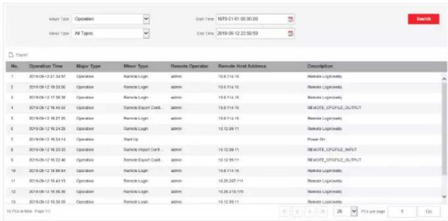
Figure 5-8 Log Management
-
Set search conditions, including Major Type, Minor Type, Start Time and End Time.
-
Click Search.

Note
A maximum of 2000 search results can display. Please narrow down the search scope if there are too many search results.
- Optional: Click Export to export all the search results.

Note
Logs can be exported in Excel. A prompt window will pop up when the logs are exported successfully.
5.7 Network Diagnostics
With network diagnostics, troubleshooting engineers can locate network faults quickly.
Steps
- Go to System Management → System Tools → Network Diagnostics.
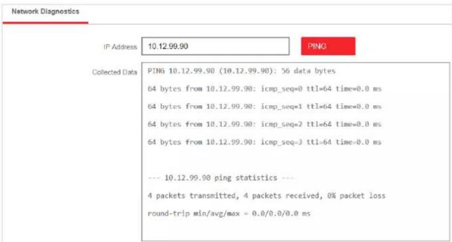
Figure 5-9 Network Diagnostics
- Enter the IP address of the server, and click PING.
5.8 User Management
Regularly change the password can guarantee the security of the device.
Steps
- Go to System Management → User Management.
- Click Edit.
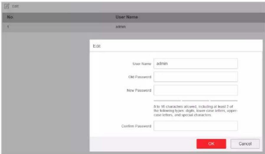
Figure 5-10 User Management
- Enter the old password.
- Enter a new password and confirm it.
- Click OK.
5.9 Security Management
SSH
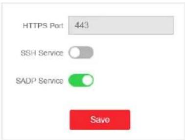
bar
| Category | Value | |---|---| | HTTPS Port | 443 | | SSH Service | | | | SADP Service | | | | | | Savo | | | | | | Savo | | | | | | Savo | | | | | | | | | | | | | | | | | | | | | | | | | | | | | | | | | | | | | | | | | | | | | | | | | | | / | SAPD Service SAPD Service SAPD Service SAPD Service SAPD Service SAPD Service SAPD Service SAPD Service SAPD Service SAPD Service SAPD Service SAPD Service SAPD Service SAPD Service SAPD Service SAPD Service SAPD Service SAPD Service SAPD Service SAPD Service SAPD ServiceFigure 5-11 Security Management
The device supports SSH security service. SSH can prevent the information leakage in the remote management of the device. SSH is disabled by default.

Note
The user name of SSH is root, and the password is the device login password.
SADP
After enabling SADP, you can activate the device, change the password and the network information, and etc. SADP is enabled by default.
5.10 Configure Network
Configure network and Ezviz parameters for the device.
Steps
- Configure basic network parameters.
1) Go to System Management → Network Configuration → Basic Config.
2) Enter IP Address, Mask Address, Gateway Address, DNS, and Alternative DNS Server.
3) Click Save.
- Set and check Ezviz information.
1) Go to System Management → Network Configuration → Ezviz Config.
2) Enable or disable Ezviz.
3) Enter operation code of Ezviz.
4) Click Save.

See Far, Go Further
- About this Manual
- Trademarks
- Disclaimer
- Regulatory Information
- FCC Information
- FCC Conditions
- EU Conformity Statement
- Industry Canada ICES-003 Compliance
- Preface
- Applicable Models
- About the Default
- Symbol Conventions
- Safety Instruction
- Danger
- Caution
- Contents
- Chapter 1 Product Introduction ...... 1
- Chapter 2 Activation and Login ...... 2
- Chapter 3 Device Management .... 4
- Chapter 4 Switch Configuration ...... 7
- Chapter 5 System Management ...... 24
- Chapter 1 Product Introduction
- Chapter 2 Activation and Login
- Before You Start
- Steps
- i Note
- Chapter 3 Device Management
- Working Status
- Port Status
- Port Statistics
- PoE Status
- Chapter 4 Switch Configuration
- Port Configuration
- Attribute Configuration
- Speed
- Duplex
- Flow Control
- Enable
- Configure Port Mirroring
- Disable Mirror
- Inbound
- Outbound
- Inbound and Outbound
- Note
- Long-Range Mode Configuration
- Configure Port Isolation
- Link Aggregation Configuration
- Source and Destination MAC
- VLAN Configuration
- Add a VLAN
- Enter a VLAN ID.
- Optional: You can also delete a VLAN by clicking Delete.
- Configure a Port
- iNote
- QoS Configuration
- NORMAL
- SP
- WRR
- SNMP Configuration
- SNMP Proxy Settings
- Community Name
- SNMP Trap Settings
- STP Configuration
- Global Configuration
- STP Port Configuration
- Configure the Port Priority.
- Port Priority
- Click Save.
- STP Status View
- PoE Management
- PoE Settings
- PoE Watchdog
- Chapter 5 System Management
- Time Sync
- Device Operation
- Restart
- Restore
- Configuration File Export
- Click OK.
- Configuration File Import
- Device Upgrade
- Result
- Log Management
- Network Diagnostics
- User Management
- Security Management
- SSH
- SADP
- Configure Network
Brand : Hikvision
Model : DS-3E1310P-SI
Category : Network switch